Trelawny 1B Manual
NEEDLE & CHISEL SCALERS
OPERATION & MAINTENANCE

OPERATION
General Information
Before operating, performing maintenance or
repairing the Needle / Chisel Scaler this
manual must be read and understood by the
operator, if in any doubt, ask your supervisor
before using this equipment.
Local safety regulations must be followed at
all times. Failure to follow these instructions
could result in damage to the Scaler and/or
personal injury.
Trelawny SPT Limited disclaims all
responsibility for damage to persons or
objects arising as a consequence of incorrect
handling of the tool, failure to inspect the tool
for damage or other faults that may influence
the operation prior to starting work, or failure
to follow the safety regulations listed or
applicable to the job site.
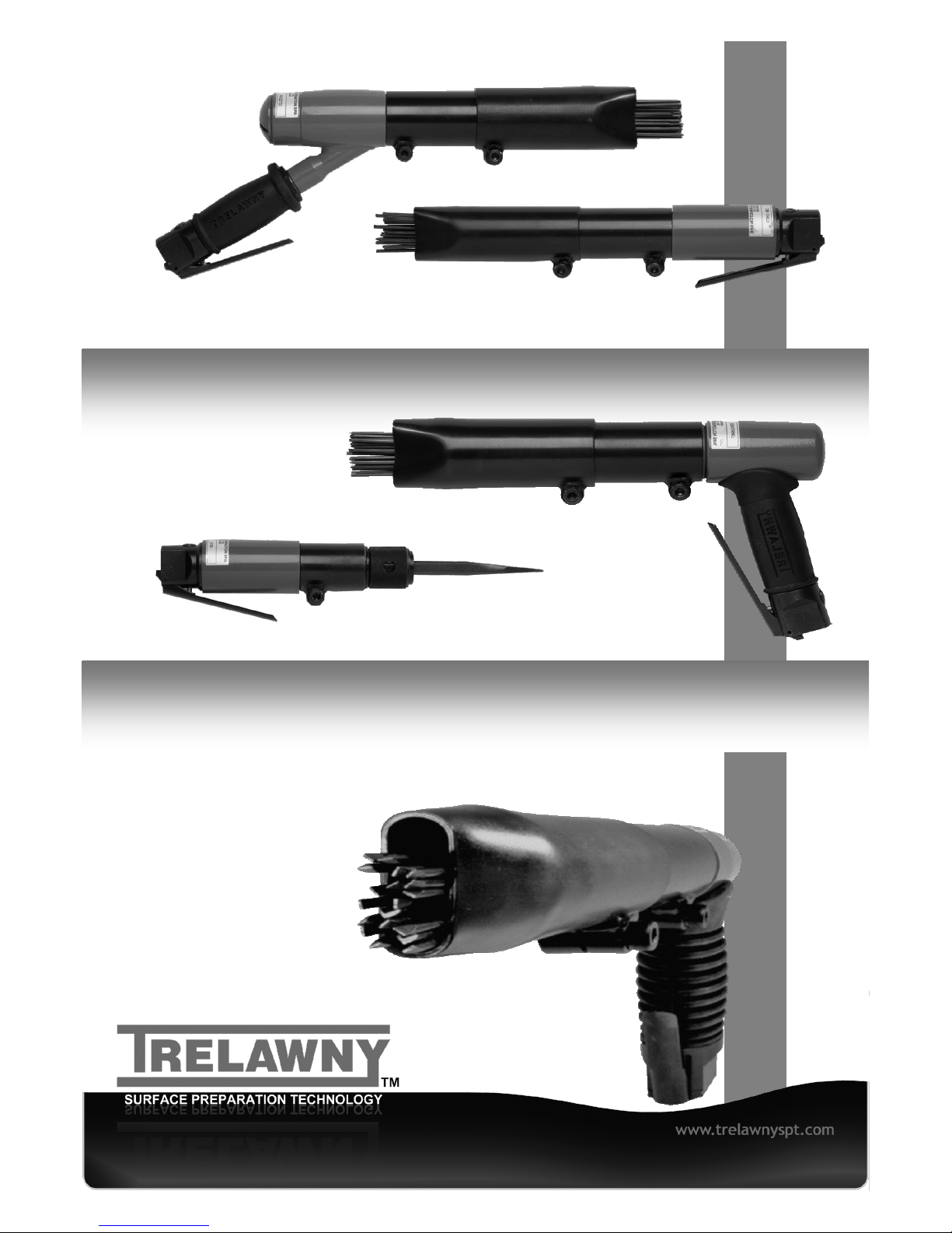
The tool is primarily designed for the removal
of paint, heavy rust, and scale; it can also be
used for the removal of laitance from
concrete. It can be used both indoors and out.
This tool must not be used in a fixture.
Air Supply
The compressed air must be free from water
and dirt. The installation of a filter/regulator/
lubricator air preparation set (with moisture
trap) adjacent to the tool is strongly
recommended.
Always clear the air hose before connecting to
the tool. Ensure that no moisture
(condensation) is present in the air hose.
Ensure that a minimum 10mm (3/8”) bore air
hose is used and that all couplings are
secure, leak free and in good condition.
Limit the length of air hose to 10M (33ft).
Where extra length is necessary, for each
additional 15M (50ft) of air hose used, the
pressure drop is approximately 0.21bar
(3psi).
For safe and efficient operation the correct
operating pressure is 6.2bar (90 psi).
Do not let the operating pressure fall below
5.5bar (80p.s.i.) or rise above 6.9bar (100 psi)
absolute maximum.
Preferably, the compressor should be able to
supply a minimum of 4.7 L/s (10 cfm) free air
for the largest Needle / Chisel Scaler and 2.8
L/s (6 cfm) for the 1B Needle / Chisel Scaler.
In particularly cold weather it is recommended
that a proprietary anti-freeze lubricating oil is
used.
Lubrication
Oil the tool daily before use. Put a few drops
of one of the following zinc free air tool
lubricants through the air inlet.
SHELL S22 or R10
CASTROL Hyspin ZZ32
See also the section on AIR SUPPLY for
further information and recommendations.
Safety
Always, read through these instructions first
before use.
Do-
Be aware that this tool is not electrically
insulated.
Wear Personal Protective Equipment
including safety goggles, footwear, ear
defenders and gloves. In some environments
it will be necessary to wear
facemasks or breathing apparatus.
Be aware that this tool can create dust and
flying debris.
Keep hands and clothing away from moving
parts.
Store this tool in a secure and dry
environment.
Be aware of others working around you.
Ensure that this tool is lubricated daily.
Always observe safe-working practices at
all times.
Do not-
Allow the tool to run unattended.
Modify this tool in any way, as this will
invalidate the warranty and could lead to
serious injury.
Allow the tool to run continuously whilst not in
contact with the surface being prepared.
Use the tool if you become tired, this can lead
to physical strain or injuries; where practical;
use a spring balance to take the weight of the
tool.
Hold the exposed needles, whilst the tool is in
use, this could cause vibration damage to the
hands.
Use this tool in potentially explosive
environments.
Drag this tool by the air hose.
Use petrol (gasoline), thinners or any other
high flash point solvent to clean the tool.
Please note: Unrestrained hoses can whip
dangerously if they become detached.
Care must be taken to avoid damaging or
tripping over the trailing air hose.
Risk of Hand-arm
Vibration injury
These tools may cause Hand-arm Vibration
Syndrome injury if their use is not adequately
managed.
We advise you to carry out a risk assessment
and to implement measures such as; limiting
exposure time [i.e. actual trigger time, not total
time at work], job rotation, ensuring the tools
are used correctly, ensuring the tools are
m a i n t a i n e d a c c o r d i n g t o o u r
recommendations, and ensuring that the
operators wear personal protective equipment
[PPE] particularly gloves and clothing to keep
them warm and dry.
Employers should consider setting up a
programme of health surveillance to establish
a benchmark for each operator and to detect
early symptoms of vibration injury.
We are not aware of any PPE that provides
protection against vibration injury by
attenuating vibration emissions.
See ‘Specifications’ section for vibration
emission data.
Further advice is available from our Technical
Department.
We strongly advise you to visit the Health &
S a fe t y E x ec u ti v e w e b si t e h t t p: / /
www.hse.gov.uk/vibration This site provides
excellent advice and information on HAV and
it includes a Hand-arm Vibration Exposure
Calculator that is easy to use to work out the
daily vibration exposure for each of your
operators.
Starting work
Please note:
The carbon steel needles provided with these
tools are not intended for use in a potentially
explosive atmosphere.
Prior to operating the tool check: -
That all fittings are secure, free from leaks
and air hoses are in good condition.
That the air pressure is correct for this tool
6.2 bar (90 p.s.i.).
Put a few drops of a recommended lubricant
into the air inlet of the tool.
To operate the tool, which is dependant on
the type of lever fitted, for those fitted with a
safety lever, first push thumb button forwards
and then for both styles of lever, pull the lever
towards the hand grip to start the tool, then
apply the Chisel or Needles to the surface
being prepared.
Note: Several types of Chisel are available for
the Chisel Scaler to suit the job in hand; a
Needle Scaler Attachment to convert a Chisel
Scaler into a Needle Scaler is also available.
See parts list for details.
To switch off, simply release the throttle
lever.
It is advisable that gloves and personal
protective equipment be worn when using this
tool.
(See previous section on Risk of Vibration
Injury).
Take care to avoid tripping over or damaging
the air hose.
Safe use of this tool requires a solid stance
and secure foothold, the tool may be used in
other postures but care must be taken to
ensure the operator adopts a firm and stable
position.
Maintain contact with the work surface with
sufficient pressure to keep the tool from
bouncing off the surface.
Handled correctly Trelawny Needle/Chisel
Scalers will work quickly and efficiently.
Excessive operator pressure will not improve
the tools efficiency but could cause premature
tool failure and increase operator fatigue.
It could also increase the vibration emission
level.
MAINTENANCE
Pointed tip needles
Sharpened to a nail point, these are most
effective in breaking through very hard scale
on surfaces where some surface indentation
is permissible - or where keying (i.e. profile) of
the surface is desirable.
Pointed tip needles are available in 3mm and
4mm only.
Chisel tip needles
These are general purpose needles, flattened
to a chisel like blade and are most effective in
the removal of thicker material, while leaving a
less pitted surface than the Pointed tip
needles but still giving some surface
indentation (i.e. profile).
Chisel tip needles are available in 3mm only.
Flat tip needles
Machined to a flat tip, these needles will leave
slight marking (i.e. profile) on the surface; the
2mm needles can have a burnishing effect.
2mm Needles are recommended for use on
thin gauge metals and any surface where light
treatment is desired.
Flat tip needles are available in three sizes -
2mm, 3mm and 4mm.
SEE SPECIFICATION SECTION FOR
QUANTITIES.
Fitting the
Chisel Holder
Before fitting the Chisel Holder (31),
disconnect the tool from the air supply,
slacken the pinch bolt on the Needle Holder
Assembly and remove the Assembly, taking
care not to allow the internal components to
fall out.
To fit the Chisel Holder (31) ensure that the
pinch bolt (30) on the Chisel Holder (31) is
loose, screw the Chisel Holder (31) fully on to
the Cylinder (10) or Body (13).
Then unscrew to position the boss
underneath.
Turn the knurled collar on the Chisel Holder
(31) until the retaining ball is fully visible;
insert the Chisel (32) aligning the rebate with
the ball.
Position the midpoint of the rebate on the
shank of the Chisel (32) with the retaining ball
and turn the collar half a turn to lock the
Chisel (32) in place.
Tighten the pinch bolt (30) using a 6mm AF
Allen key. To release the Chisel (32), rotate
the knurled collar until the retaining ball is fully
visible and remove the Chisel (32).
Fitting of the Needle Scaler Attachment
Before fitting the Needle Scaler Attachment,
disconnect the air supply from the tool,
slacken the pinch bolt on the Chisel Holder
and remove Chisel Holder.
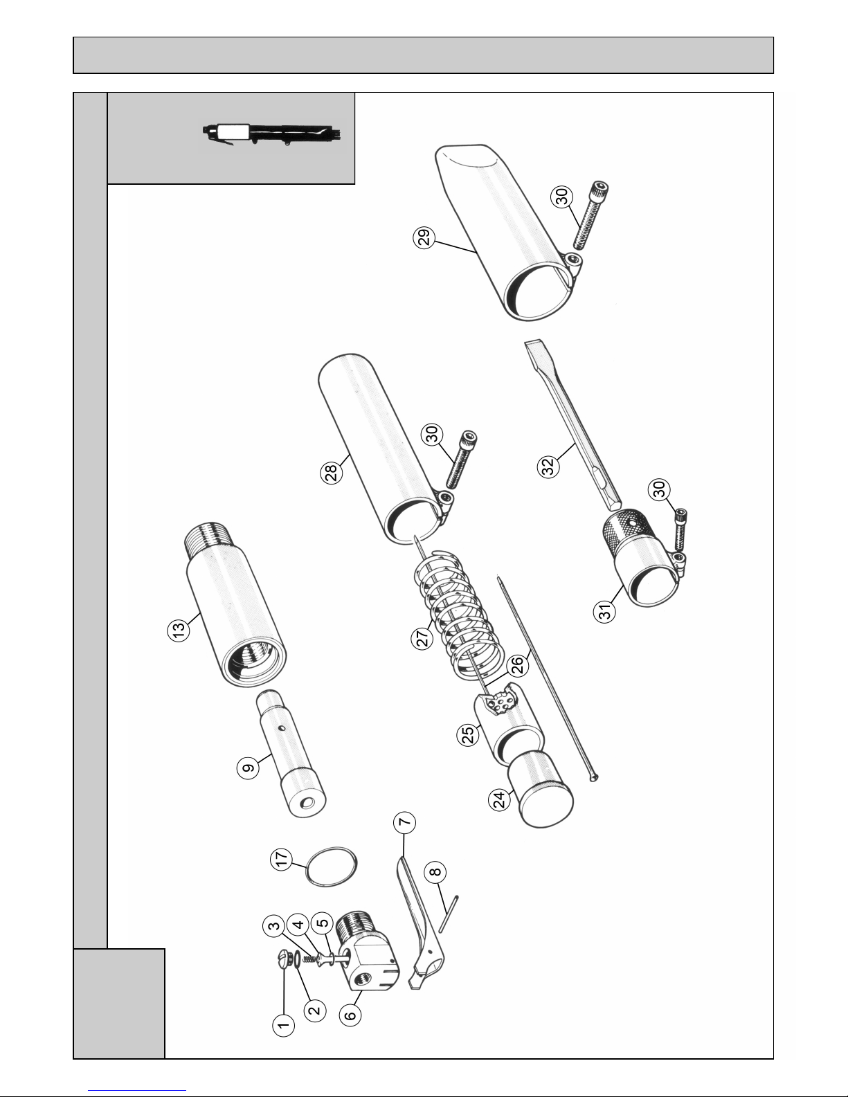
Assemble the component parts of the Needle
Scaler attachment in the following order;
insert the Needles (26) into the Needle Holder
(25),
place the Spring (27) over the Needles, insert
the Anvil (24), small diameter first, into the
Needle Holder (25), then place the assembly
into the Intermediate Tube (28).
Check the service layout for clarification.
Screw the assembly fully onto the Cylinder
(10) or Body (13) and tighten the pinch bolt
(30) using a 6mm AF Allen key.
Slide the Front Tube (29) on to the
Intermediate Tube (28) until approximately
25mm (1”) of Needle protrudes from the Front
Tube (29). Tighten the pinch bolt (30) using a
6mm AF Allen key.
Dismantling
Remove all deposits from outside of the
Needle/Chisel Scaler and disconnect the tool
from the air hose.
Slacken the pinch bolt on the Needle Holder
Assembly or Chisel Holder and carefully
unscrew from the Body/Cylinder.
Take care not to allow the internal
components to fall out of the Needle Holder
Assembly.
All Valve Body Servicing
Clamp the Valve Body (6) firmly in a vice,
using the flats provided, and with the Throttle
Lever (7) upper most.
Using a 3mm diameter pin or punch and small
hammer, remove the Throttle Lever Roll Pin
(8), and remove the Throttle Lever (7).
Rotate the Valve Body (6) 180 degrees in the
vice to gain access the Valve Cap (1).
Unscrew the Valve Cap (1) using a
screwdriver, check the Valve Cap O’ Ring (2)
for signs of deterioration, remove the Spring
(3), push out the Valve Stem (4) and remove
the valve seat O’ Ring (5).
Check the Valve Stem (4) and O’ Ring (5) for
wear.
Piston and Cylinder removal
To remove the Piston (9) or Cylinder from
each of the three styles of Needle/Chisel
Scaler, refer to the specific instructions below.
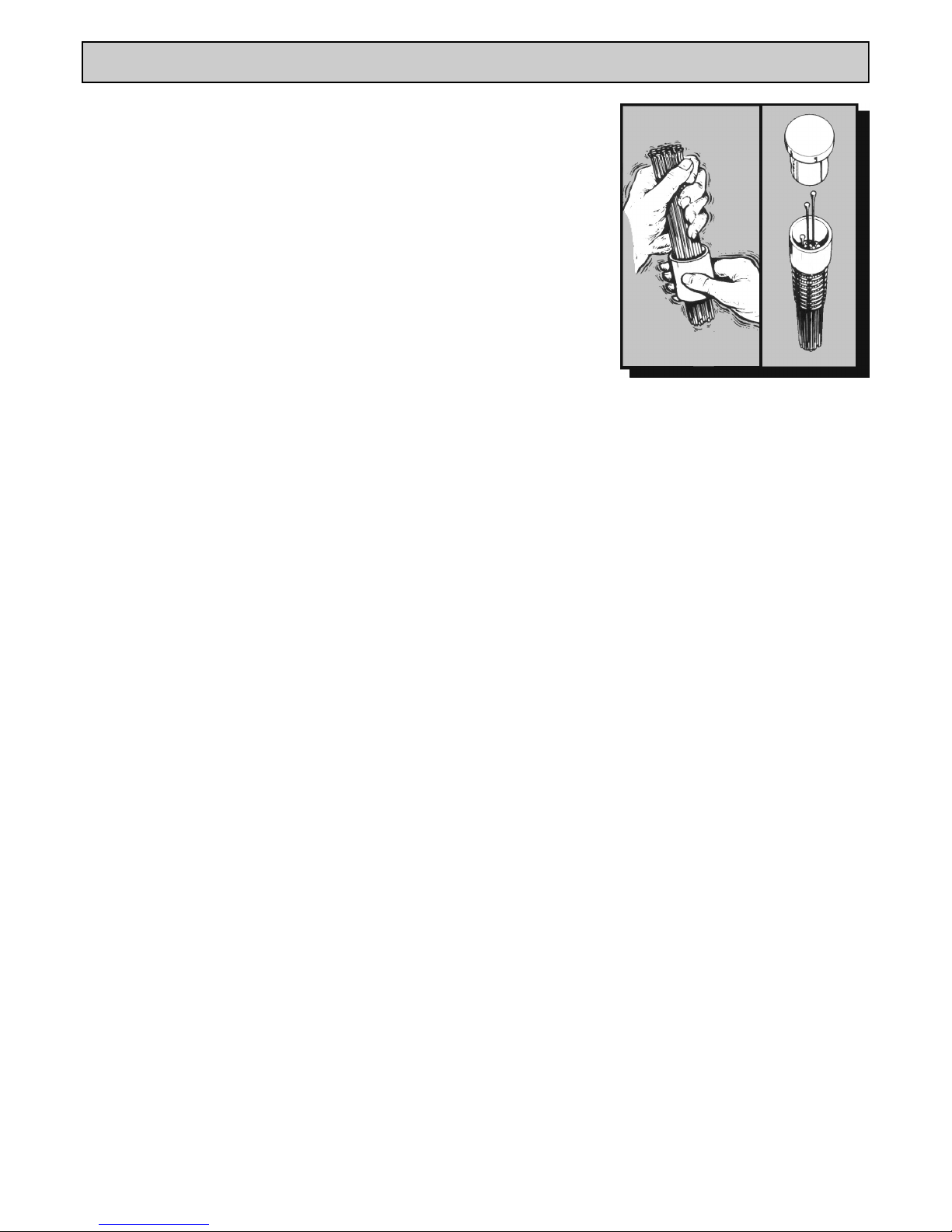
Hold the needles loosely
and shake the holder,
needles will fall into location
holes
The correct
position of parts
when changing
needles
Never allow the tool to run continuously
whilst not in contact with the surface being
prepared.
Maintenance
Only a competent person, in a suitably
equipped workshop, must carry out
maintenance.
Disconnect the tool from the air supply
before carrying out any maintenance or
any of the operations in the next sections.
Clean all debris from the exterior of the tool.
For safe efficient running and at intervals of
no more that 100hrs or if operation becomes
sluggish, dismantle and clean with highly
refined paraffin. Immediately after cleaning,
thoroughly oil the tool with one of the
recommended lubricants.
Changing
Needles
Before changing or replacing needles,
disconnect the air supply to the tool.
Loosen the Cap Head Screw (30) on the
Intermediate Tube (28) and remove the Tube
Assembly, taking care not to allow the internal
components to fall out.
Please note:
Models 1B, 2B and 2BPG have a grip thread
–there is no thread in the intermediate tube.
Models 3B, 3BPG & 4B have screw threads.
Take note when disassembling how all the
parts inside the Intermediate Tube (28) fit
together as wrong assembly will result in
damage to the tool.
Remove the Needle Holder (25) and Anvil
(24) as an assembly from the Intermediate
Tube, check that the Return Spring (27) fitted
inside the Intermediate Tube is in good
condition.
Remove the Needles from the Needle Holder
and replace with new Needles as per the
illustration.
On assembly ensure that the small diameter
of the Anvil (24) fits inside the Needle Holder
(25).
Place the Return Spring over the Needles and
fit the assembly into the Intermediate Tube.
Fully screw the Tube Assembly onto the
Body/Cover.
Position the boss underneath and tighten the
Allen Screw (30).
As the Needles wear, adjust the Front Tube
by loosening the Allen Screw and adjusting
the Front Tube so that approximately
1” (25mm) of Needle protrudes from the Front
Tube (29) and then retighten the Allen Screw.

SERVICING
Risk of Hand Arm
Injury
Because of various factors, the range of
vibration emission during intended use of
these tools are expected to be between
8.5m/s2and 84m/s2dependent on the tool
purchased. The vibration is dependent on the
task, the operators grip, and feed force
employed etc.
Vibration measured in accordance with:-
EN ISO 28927 and EN ISO 20643
Declared vibration emission values were
obtained under laboratory conditions in
compliance with the above stated standards
and do not necessarily represent values
obtained in service.
Disposal
When the tool and its accessories are taken
out of service for disposal, it is recommended
that:-
They are rendered unusable to prevent
improper re-use. They are dismantled into
component form, segregated according to
material composition and disposed of using
waste recycling processes specified by local
regulations.
Note:
Flammable material such as plastic, rubber or
composite materials must NOT be incinerated
but should be subject to normal industrial
waste disposal processes.
Machinery Directive
Information
This tool has been designed and produced in
accordance with the following directive:
2 00 6 / 42 / EC M ac hi n er y Di r e ct i ve
a n d a p p l i c a bl e h a rm o n i s e d s t a n d a r d :
EN ISO 1 1148-4:2010
STYLE A
Hold the Body (13) vertically in a vice. Insert
the Piston (9), small diameter first into the
bore.
Fit a new O’Ring (17) onto the shoulder near
the top of the body.
Screw the Valve body by hand into the Body,
and then tighten using a suitable spanner
using the flats provided.
STYLE B
Fit two new O’Rings (11) and (12) onto the
Cylinder (10).
Insert the Piston (9), small diameter first into
the bore.
With clean, dry and oil free threads apply a
bead of Loctite 243 or similar adhesive to the
central portion of the Cylinder (10) threads.
Screw the Cylinder (10) fully into the Cover
Assembly (14) by hand.
Then holding the Cylinder in a vice using the
flats provided, tighten fully by hand, then,
using a rubber mallet, tap lightly on the handle
until tightened fully.
STYLE C
Hold the body (13) vertically in a vice, with the
handle uppermost, insert the Cylinder (10),
small bore first into the Body (13), then the
Piston (9), small diameter first, into the
Cylinder (10).
Fit a new O’Ring (17) into the Body (13) to sit
on top of the Cylinder (10).
Screw the End Cap (15) down by hand, then
using a suitable wrench tighten fully.
Noise and Vibration
UK employers should be aware of their duties
under the Health & Safety at Work Act 1974
and the guidance given regarding hand arm
vibration in the H.S.E. publication “Control the
risks from hand-arm vibration” INDG175
(rev2).
(Single copies are available F.O.C. See
H.S.E. web site www.hse.gov.uk)
Employers in the rest of the world should be
aware of their duties and responsibilities as
specified in local regulations.
The employer is responsible for assessing the
risk to the employee under actual working
conditions.
Noise level measured in accordance with
EN ISO 15744: 1999
STYLE A
Hold the Body (13) firmly in a vice, with the
Valve Body (6) uppermost and using a
suitable wrench and using the flats provided,
unscrew the Valve Body (6).
Remove the O’Ring from the Body (13) then
remove the Piston (9).
Inspect all components for signs of wear,
particularly the small bore of the Body,
replace components as necessary.
STYLE B
Hold the Cylinder (10) firmly in a vice, using
the flats provided and with the Valve
Assembly uppermost, unscrew the cover (14)
from the cylinder (10).
The Cylinder (10) has been secured with a
retaining compound and may require a sharp
blow on the handle using a rubber mallet to
break this bond.
Remove the two O’Ring seals (11) and (12)
and the Piston (9).
Inspect all components for signs of wear,
particularly the small bore of the Cylinder,
replace components as necessary.
STYLE C
Hold the Body (13) vertically in a vice, with the
handle uppermost and unscrew the End Cap
using a suitable wrench.
Remove the O’Ring (17), Piston (9) and
Cylinder (10).
Inspect all components for signs of wear,
particularly the small bore of the cylinder,
replace components as necessary.
Assembly
Before any assembly takes place, ensure all
parts are clean and are coated in a thin film of
recommended air tool lubricant.
It is strongly recommended that all the
O’ Rings and any other worn parts that show
signs of wear be replaced using only genuine
Trelawny spares.
All Valve Body Assemblies
Clamp the Valve Body firmly in a vice, using
the flats provided, and with the threaded hole
uppermost.
Insert the valve seat O’ Ring (5) into Valve
Body (6), followed by the Valve Stem (4),
Spring (3), then the Valve Cap (1) complete
with its O’ Ring (2), tighten the Valve Cap (1)
with a screwdriver.
Rotate assembly 180 degrees in the vice.
Using a 3mm diameter pin punch locate and
align the Throttle Lever (7) in position, then
drive in the Throttle Lever Roll Pin (8) into the
pin location.
Piston and Cylinder Assembly
To assemble the Scaler with a new Piston (9)
or Cylinder (10), refer to the specific
instruction for each style.
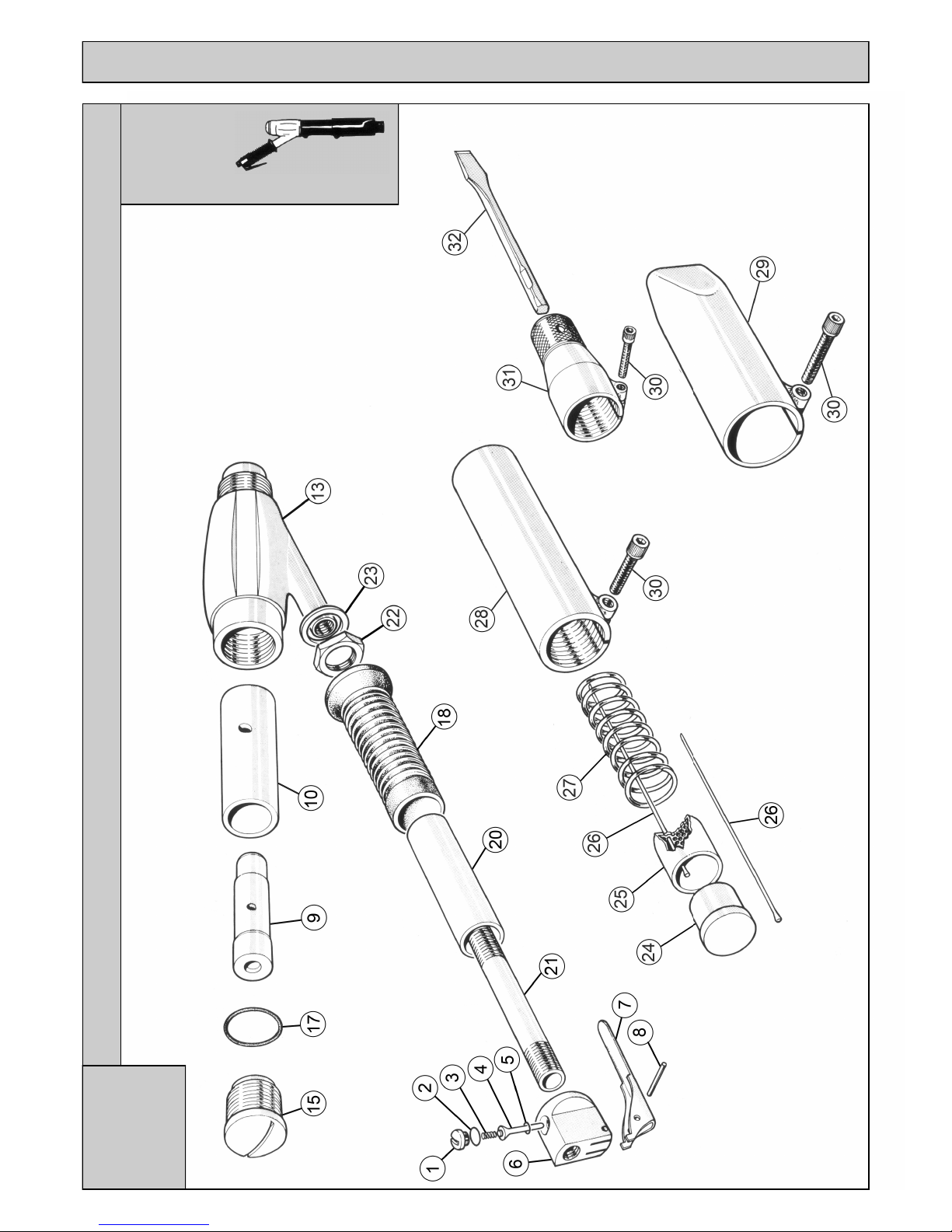
EXPLODED VIEW
Service
Layout
Style A
1B & 2B INLINE NEEDLE, CHIPPER & CHISEL SCALER
Service
Layout
Style A

Item Part No Description Item Part No Description
Common Components 1B Unique Components
1 615.3021 Valve Cap 6 423.1021 Valve Body (inc 1-8) 1/4” BSP Thread
2 809.0139 O’ Ring – Valve Cap 423.1521 Valve Body (inc 1-8) 1/4” NPT Thread
3 712.3022 Valve Spring 7 716.3021 Throttle Lever
4 618.3022 Valve Stem 9 612.1001 Piston
5 809.0089 O’ Ring – Valve Seat 13 411.1002 Body
8 813.0108 Roll Pin 17 809.0249 O’Ring
26 442.1107 Pack of 2000 2mm Needles (Flat Tip) 24 610.1001 Anvil
452.1110 Pack of 100 2mm Needles (Flat Tip) 25 601.1002 Needle Holder 2mm
443.2107 Pack of 1000 3mm Needles (Chisel Tip) 601.1003 Needle Holder 3mm
443.1107 Pack of 1000 3mm Needles (Flat Tip) 26 412.1129 6 x Needle Sets 2mm (Flat Tip)
443.3107 Pack of 1000 3mm Needles (Pointed Tip) 413.2112 6 x Needle Sets 3mm (Chisel Tip)
443.1307 Pack of 500 3mm Needles (Beryllium Copper) 413.1112 6 x Needle Sets 3mm (Flat Tip)
453.2110 Pack of 100 3mm Needles (Chisel Tip) 413.3112 6 x Needle Sets 3mm (Pointed Tip)
453.1110 Pack of 100 3mm Needles (Flat Tip) 403.1312 1 x Needle Set 3mm (Beryllium Copper - Flat Tip)
453.3110 Pack of 100 3mm Needles (Pointed Tip) 27 712.1001 Spring - Compression
453.1310 Pack of 100 3mm Needles (Beryllium Copper) 28 416.1032 Intermediate Tube (Includes item 30)
444.2107 Pack of 500 4mm Needles (Chisel Tip) 29 417.1032 Straight Front Tube (Includes item 30)
444.1107 Pack of 500 4mm Needles (Flat Tip) 418.1032 Round Front Tube (Includes item 30)
444.3107 Pack of 500 4mm Needles (Pointed Tip) 30 806.0825 Cap Head Screw
31 419.1241 Chisel Holder 1/2” Square
446.1010 Service Kit (Inc. 9,17,24,25,27 & 1 Set Needles)
454.2105 Pack of 50 4mm Needles (Chisel Tip)
454.1105 Pack of 50 4mm Needles (Flat Tip) 2B Unique Components
454.3105 Pack of 50 4mm Needles (Pointed Tip) 6 423.2021 Valve Body (inc 1-8) 1/4” BSP Thread
32 704.1101 Chisel 1/2” Square 7” Long x 3/4” Blade 423.2521 Valve Body (inc 1-8) 1/4” NPT Thread
704.1103 Chisel 1/2” Square 7” Long x 2 3/4” Blade 7 716.3000 Throttle Lever
704.1106 Chisel 1/2” Square Brick Rake 9 612.2001 Piston
704.1110 Chisel 1/2” Square 7” Long Spark Resistant 2 ” Blade 13 411.2002 Body
704.2105 Chisel 1/2” Square 7” Long Cranked x 1 3/8” Blade 17 809.5179 O’Ring
24 610.2001 Anvil
25 601.2002 Needle Holder 2mm
601.2003 Needle Holder 3mm
26 412.1151 6 x Needle Sets 2mm (Flat Tip)
413.2119 6 x Needle Sets 3mm (Chisel Tip)
413.1119 6 x Needle Sets 3mm (Flat Tip)
413.3119 6 x Needle Sets 3mm (Pointed Tip)
403.1319 1 x Needle Set 3mm (Beryllium Copper - Flat Tip)
27 712.2001 Spring - Compression
Extras 28 416.2032 Intermediate Tube (Includes item 30)
719.1000 3/8” Bore Hose 10 Metre 29 417.2032 Straight Front Tube (Includes item 30)
719.3000 3/8” Bore Hose 30 Metre 418.2032 Round Front Tube (Includes item 30)
805.0601 6mm Allen Key for Caphead Screws 30 806.0830 Cap Head Screw
819.2375 Adapter 1/4” BSP to 3/8” Hose Stem 31 419.2241 Chisel Holder 1/2” Square
446.1020 Service Kit (Inc. 9,17,24,25,27 & 1 Set Needles)
1B & 2B PARTS LIST
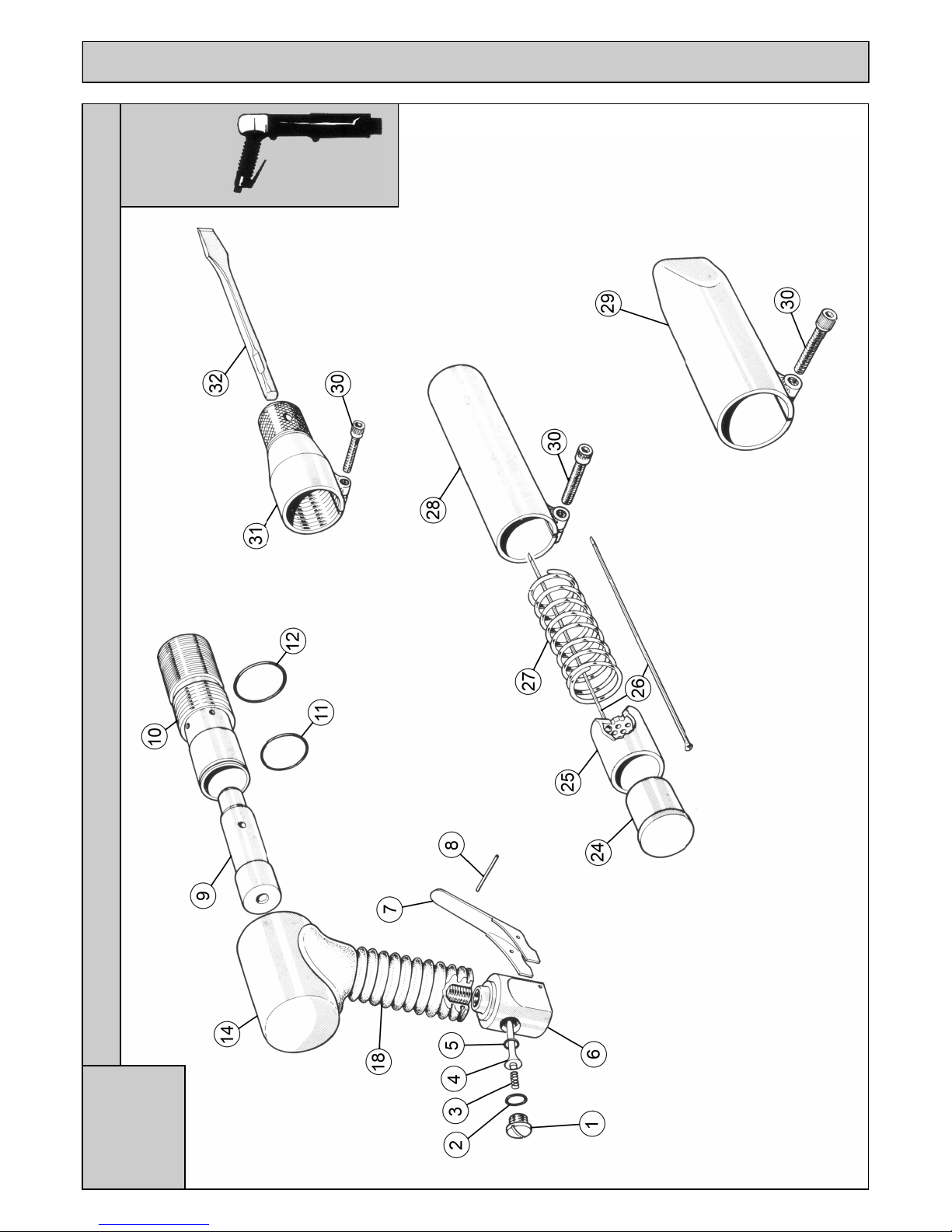
2BPG & 3BPG PISTOL GRIP NEEDLE & CHISEL SCALER
EXPLODED VIEW
Service
Layout
Style B
Service
Layout
Style B

Item Part No Description Item Part No Description
Common Components 2BPG Unique Components
1 615.3021 Valve Cap 9 612.2001 Piston
2 809.0139 O’ Ring – Valve Cap 10 613.2101 Cylinder
3 712.3022 Valve Spring 11 809.0249 O’Ring (Small Dia)
4 618.3022 Valve Stem 12 809.0269 O’Ring (Large Dia)
5 809.0089 O’ Ring – Valve Seat 13 425.2100 Cover
6 616.3021 Valve Body 1/4” BSP Thread 24 610.2001 Anvil
423.3021 Valve Body Assembly (inc items 1-8) 1/4” BSP Thread 25 601.2002 Needle Holder 2mm
423.3521 Valve Body Assembly (inc items 1-8) 1/4” NPT Thread 601.2003 Needle Holder 3mm
7 716.3000 Throttle Lever 26 412.1151 6 x Needle Sets 2mm (Flat Tip)
8 813.0108 Roll Pin 413.2119 6 x Needle Sets 3mm (Chisel Tip)
18 717.3101 Rubber Grip 413.1119 6 x Needle Sets 3mm (Flat Tip)
26 442.1107 Pack of 2000 2mm Needles (Flat Tip) 413.3119 6 x Needle Sets 3mm (Pointed Tip)
452.1110 Pack of 100 2mm Needles (Flat Tip) 403.1319 1 x Needle Set 3mm (Beryllium Copper - Flat Tip)
443.2107 Pack of 1000 3mm Needles (Chisel Tip) 27 712.2001 Spring - Compression
443.1107 Pack of 1000 3mm Needles (Flat Tip) 28 416.2032 Intermediate Tube (Includes item 30)
443.3107 Pack of 1000 3mm Needles (Pointed Tip) 29 417.2032 Straight Front Tube (Includes item 30)
443.1307 Pack of 500 3mm Needles (Beryllium Copper) 418.2032 Round Front Tube (Includes item 30)
453.2110 Pack of 100 3mm Needles (Chisel Tip) 30 806.0830 Cap Head Screw
453.1110 Pack of 100 3mm Needles (Flat Tip) 31 419.2241 Chisel Holder 1/2” Square
453.3110 Pack of 100 3mm Needles (Pointed Tip) 446.1025 Service Kit (Inc. 9,17,24,25,27 & 1 Set Needles)
453.1310 Pack of 100 3mm Needles (Beryllium Copper)
444.1107 Pack of 500 4mm Needles (Flat Tip) 3BPG Unique Components
444.3107 Pack of 500 4mm Needles (Pointed Tip) 9 612.3001 Piston
454.1105 Pack of 50 4mm Needles (Flat Tip) 10 613.3101 Cylinder
454.3105 Pack of 50 4mm Needles (Pointed Tip) 11 809.0289 O’Ring (Small Dia)
32 704.1101 Chisel 1/2” Square 7” Long x 3/4” Blade 12 809.0299 O’Ring (Large Dia)
704.1103 Chisel 1/2” Square 7” Long x 2 3/4” Blade 13 425.3100 Cover
704.1106 Chisel 1/2” Square Brick Rake 24 610.3001 Anvil
704.1110 Chisel 1/2” Square 7” Long Spark Resistant 2 ” Blade 25 601.3002 Needle Holder 2mm
704.2105 Chisel 1/2” Square 7” Long Cranked x 1 3/8” Blade 601.3003 Needle Holder 3mm
26 412.1165 6 x Needle Sets 2mm (Flat Tip)
413.2128 6 x Needle Sets 3mm (Chisel Tip)
413.1128 6 x Needle Sets 3mm (Flat Tip)
413.3128 6 x Needle Sets 3mm (Pointed Tip)
403.1328 1 x Needle Set 3mm (Beryllium Copper - Flat Tip)
Extras 27 712.3001 Spring - Compression
719.1000 3/8” Bore Hose 10 Metre 28 416.3132 Intermediate Tube (Includes item 30)
719.3000 3/8” Bore Hose 30 Metre 29 417.3032 Straight Front Tube (Includes item 30)
805.0601 6mm Allen Key for Caphead Screws 418.3032 Round Front Tube (Includes item 30)
819.2375 Adapter 1/4” BSP to 3/8” Hose Stem 30 806.0830 Cap Head Screw
31 419.3341 Chisel Holder 1/2” Square
419.3541 Chisel Holder 5/8” Hexagon
446.1035 Service Kit (Inc. 9,17,24,25,27 & 1 Set Needles)
2BPG & 3BPG PARTS LIST
EXPLODED VIEW
Service
Layout
Style C
3B & 4B BACK HANDLE NEEDLE & CHISEL SCALER
Service
Layout
Style C

Item Part No Description Item Part No Description
Common Components 3B Unique Components
1 615.3021 Valve Cap 9 612.3001 Piston
2 809.0139 O’ Ring – Valve Cap 10 613.3001 Cylinder
3 712.3022 Valve Spring 13 611.3002 Body
4 618.3022 Valve Stem 15 615.3001 End Cap
5 809.0089 O’ Ring – Valve Seat 17 809.0269 O’Ring
6 616.3021 Valve Body 24 610.3001 Anvil
423.3021 Valve Body (items 1-8) 1/4” BSP Thread 25 601.3002 Needle Holder 2mm
423.3521 Valve Body (items 1-8) 1/4” NPT Thread 601.3003 Needle Holder 3mm
7 716.3000 Throttle Lever 601.3004 Needle Holder 4mm
8 813.0108 Roll Pin 26 412.1165 6 x Needle Sets 2mm (Flat Tip)
18 717.3011 Rubber Handle Grip 413.2128 6 x Needle Sets 3mm (Chisel Tip)
20 624.3001 Handle Tube 413.1128 6 x Needle Sets 3mm (Flat Tip)
21 623.3001 Centre Tube 413.3128 6 x Needle Sets 3mm (Pointed Tip)
22 625.3001 Locknut 414.1119 6 x Needle Sets 4mm (Flat Tip)
23 810.9000 Sealing Washer 414.3119 6 x Needle Sets 4mm (Pointed Tip)
26 442.1107 Pack of 2000 2mm Needles (Flat Tip) 403.1328 1 x Needle Set 3mm (Beryllium Copper - Flat Tip)
452.1110 Pack of 100 2mm Needles (Flat Tip) 27 712.3001 Spring - Compression
443.2107 Pack of 1000 3mm Needles (Chisel Tip) 28 416.3032 Intermediate Tube (Includes item 30)
443.1107 Pack of 1000 3mm Needles (Flat Tip) 29 417.3032 Straight Front Tube (Includes item 30)
443.3107 Pack of 1000 3mm Needles (Pointed Tip) 418.3032 Round Front Tube (Includes item 30)
443.1307 Pack of 500 3mm Needles (Beryllium Copper) 30 806.0830 Cap Head Screw
453.2110 Pack of 100 3mm Needles (Chisel Tip) 31 419.3241 Chisel Holder 1/2” Square
453.1110 Pack of 100 3mm Needles (Flat Tip) 446.1030 Service Kit (Inc. 9,17,24,25,27 & 1 Set Needles)
453.3110 Pack of 100 3mm Needles (Pointed Tip) 4B Unique Components
453.1310 Pack of 100 3mm Needles (Beryllium Copper) 9 612.4001 Piston
444.1107 Pack of 500 4mm Needles (Flat Tip) 10 613.4001 Cylinder
444.3107 Pack of 500 4mm Needles (Pointed Tip) 13 411.4002 Body
454.1105 Pack of 50 4mm Needles (Flat Tip) 15 615.4001 End Cap
454.3105 Pack of 50 4mm Needles (Pointed Tip) 17 809.0299 O’Ring
32 704.1101 Chisel 1/2” Square 7” Long x 3/4” Blade 24 610.4001 Anvil
704.1103 Chisel 1/2” Square 7” Long x 2 3/4” Blade 25 601.4003 Needle Holder 3mm
704.1106 Chisel 1/2” Square Brick Rake 601.4004 Needle Holder 4mm
704.1110 Chisel 1/2” Square 7” Long Spark Resistant 2 ” Blade 26 413.2149 6 x Needle Sets 3mm (Chisel Tip)
704.2105 Chisel 1/2” Square 7” Long Cranked x 1 3/8” Blade 413.3149 6 x Needle Sets 3mm (Pointed Tip)
414.1135 6 x Needle Sets 4mm (Flat Tip)
Extras 414.3135 6 x Needle Sets 4mm (Pointed Tip)
719.1000 3/8” Bore Hose 10 Metre 403.1349 1 x Needle Set 3mm (Beryllium Copper - Flat Tip)
719.3000 3/8” Bore Hose 30 Metre 27 712.4031 Spring - Compression
805.0601 6mm Allen Key for Caphead Screws 28 416.4032 Intermediate Tube (Includes item 30)
819.2375 Adapter 1/4” BSP to 3/8” Hose Stem 29 417.4032 Straight Front Tube (Includes item 30)
418.4032 Round Front Tube (Includes item 30)
30 806.0835 Cap Head Screw
31 419.4241 Chisel Holder 1/2” Square
446.1040 Service Kit (Inc. 9,17,24,25,27 & 1 Set Needles)
3B & 4B PARTS LIST

SPECIFICATION
H1* Indicates that the test was taken at the primary handgrip location, next to the throttle lever.
H2* Indicates that the test was taken at the secondary handgrip position.
(k) ** Equals the factor of uncertainty, which allows for variations in measurement and production. Vibration Data figures are tri-axial, which gives the total vibration
emission. Because of various factors, the range of vibration from these tools may vary between -0% +40%. The vibration is dependent on the task, the operators grip and
feed force employed etc.
NOTE: The above vibration levels were obtained from tri-axial measurements to comply with the requirements of “The Control of Vibration at Work Regulations 2005*” and
the revisions to the (8662) now EN ISO 28927-9:2005 and EN ISO 20643:2005 series of standards. These values are at least 1.4 times larger than the values obtained from
single axis measurements.
*Based on European Union Council Directive 2002/44/EC (Physical Agents (Vibration) Directive)
and applicable harmonised standard: EN ISO 1 1148-4:2012
All rights reserved. Any unauthorised use or copying of the contents or part thereof is prohibited.
This applies to trademarks, model denominations, part numbers and drawings.
Use only genuine Trelawny spares.
The use of non-Trelawny spare parts invalidates the warranty.
Trelawny SPT Ltd
Trelawny House, 13 Highdown Road, Sydenham Industrial Estate, Leamington Spa, Warwickshire,
CV31 1XT, United Kingdom
Telephone: +44 (0)1926 883781
Fax: +44 (0)1926 450352
Email: sales@trelawny.co.uk
Website: www.trelawnyspt.com
© TSPT UK 2009 Part No: 735.3000 issue 8
SURFACE PREPARATION TECHNOLOGY
Model Type 1B 2B 2BPG 3B 3BPG 4B
Piston Diameter 18mm (0.17”) 23.5mm (0.925”) 23.5mm (0.925”) 28.6mm (1.125”) 28.6mm (1.125”) 33.0mm (1.3”)
Piston Stroke 30.0mm (1.18”) 35.6mm (1.4”) 35.6mm (1.4”) 39.0mm (1.535”) 39.0mm (1.535”) 49.2mm (1.935”)
Blows per Minute 3800 3000 3000 2200 2200 1800
Air Consumption (1/4”BSP Air Inlet) 1.42lps (3.0cfm) 2.6lps (5.5cfm) 2.6lps (5.5cfm) 3.8lps (8.0cfm) 3.8lps (8.0cfm) 4.0lps (8.5cfm)
Handle type Straight Straight Pistol Grip Back Handle Pistol Grip Back Handle
Overall Length - Needle Scaler 343mm (13.5”) 375mm (14.75”) 315mm (12.4”) 465mm (18.3”) 343mm (13.5”) 482mm (19.0”)
Overall Length - Chisel Scaler 313mm (12.3”) 343mm (13.5”) 260mm (10.2”) 426mm (16.8”) 339mm (13.4”) 440mm (17.3”)
Nett Weight - Needle Scaler 1.6kg (3.5lbs) 2.6kg (5.7lbs) 2.6kg (5.7lbs) 4.5kg (10.0lbs) 3.7kg (8.2lbs) 5.6kg (12.4lbs)
Nett Weight - Chisel Scaler 1.5kg (3.3lbs) 2.0kg (4.4lbs) 2.0kg (4.4lbs) 3.4kg 7.5lbs) 3.0kg (6.6lbs) 4.0kg (8.8lbs)
Quantity of Needles
2mm 29 51 51 65 65 -
3mm 12 19 19 28 28 49
4mm - - - 19 19 35
Noise Level Lpa db(A) - Needle Scaler 97.4 100.3 100.3 101.5 101.5 104.4
Noise Level Lpa db(A) - Chisel Scaler 85.9 85.6 85.6 92.1 92.1 86.7
Noise Level Lwa db(A) - Needle Scaler 110.4 113.3 113.3 114.5 114.5 117.4
Noise Level Lwa db(A) - Chisel Scaler 98.9 98.6 98.6 105.1 105.1 99.7
Vibration Level AEQ - Needle Scaler H1* (k)** 8.5 9.3 12.3 12.3 19.0 23.5
Vibration Level AEQ - Needle Scaler H2* (k)** 7.4 12.5 15.0 17.3 27.6 29.4
Vibration Level AEQ - Chisel Scaler H1* (k)** 8.2 17.4 22.4 19.9 25.6 45.2
Vibration Level AEQ - Chisel Scaler H2* (k)** 8.2 19.5 32.2 24.2 33.7 60.0
This manual suits for next models
5
Table of contents
Other Trelawny Media Converter manuals


Popular Media Converter manuals by other brands


SEW-Eurodrive
SEW-Eurodrive MOVITRAC LTP-B Compact operating instructions

Zte
Zte CPC-60 owner's manual

TR-Electronic
TR-Electronic LMR-70-1200 ANA-I+JUSTAGE manual

Pro-Ject Audio Systems
Pro-Ject Audio Systems DAC Box FL Instructions for use

Atlona
Atlona AT-LINE-PRO3 user manual

Goobay
Goobay 60727 user manual