TREND NETWORKS FiberTEK IV User manual

Depend On Us
www.trend-networks.com 164818
FiberTEK IV
Quick Reference Guide

3
Depend On Us
2www.trend-networks.com 164818
FiberTEK IV
Quick Reference Guide
Bedienungsanleitung
Guide d’utilisation
Guida utente
Manual de usuario
Guia do Usuario
164818 rev2 11/2020
TREND NETWORKS
Stokenchurch House
Oxford Road
Stokenchurch
High Wycombe
Buckinghamshire
HP14 3SX
United Kingdom

3
Depend On Us
2www.trend-networks.com 164818
© TREND NETWORKS 2020
The information contained in this document is the property of TREND NETWORKS and is supplied without liability
for errors and omissions. No part of this document may be reproduced or used except as authorised by contract or
other written permission from TREND NETWORKS. The copyright and all restrictions on reproduction and use apply
to all media in which this information may be placed. TREND NETWORKS pursues a policy of continual product
improvement and reserves the right to alter without notice the specification, design, price or conditions of supply of
any product or service. All rights reserved.
English
Deutsch
Italiano
Español
Português
Français
Die Informationen in diesem Dokument sind das Eigentum von TREND NETWORKS und werden ohne
Gewährleistung der Vollständigkeit oder Korrektheit gegeben. Dieses Dokument darf nur soweit vertraglich
oder anderweitig schriftlich von TREND NETWORKS. Zugesichert ganz oder teilweise vervielfältigt werden. Das
Urheberrecht und alle Einschränkungen zur Vervielfältigung und Nutzung gelten für alle Datenträger, auf denen diese
Informationen gespeichert werden können. TREND NETWORKS bemüht sich um ständige Produktverbesserungen
und behält sich das Recht vor, die Spezifikation, das Design, den Preis oder die Lieferbedingungen jeglicher Produkte
oder Dienste ohne Vorankündigung zu ändern. Alle Rechte vorbehalten.
Les informations dans ce document sont la propriété de TREND NETWORKS et elles sont fournies sans
responsabilité pour les erreurs et les omissions. Aucune partie de ce document ne doit être reproduite ou utilisée,
sauf en cas d’autorisation par contrat ou en cas d’autre autorisation écrite donnée par TREND NETWORKS. Le
copyright et toutes les limitations concernant la reproduction et l’utilisation s’appliquent à tous les supports sur
lesquels cette information peut être placée. TREND NETWORKS améliore continuellement ses produits et se réserve
le droit de modifier sans préavis la spécification, la conception, le prix ou les conditions de fourniture d’un produit ou
d’un service. Tous droits réservés.
Le informazioni contenute nel presente documento sono di proprietà di TREND NETWORKS e sono fornite senza
alcuna responsabilità relativa a errori e omissioni. Sono vietati la riproduzione o l’uso di tutto il documento o parte
di esso, salvo se autorizzati da contratto o permesso scritto di TREND NETWORKS. Il copyright e tutte le limitazioni
sulla riproduzione e l’uso si applicano a tutti i supporti nei quali le presenti informazioni possono essere contenute.
TREND NETWORKS segue una politica volta al miglioramento continuo dei prodotti e si riserva il diritto di modificare
senza preavviso le specifiche, il disegno, il prezzo o le condizioni di fornitura di qualsivoglia prodotto o servizio. Tutti
i diritti riservati.
La información que figura en este documento es propiedad de TREND NETWORKS, quien no asume
responsabilidad alguna sobre posibles errores u omisiones que puedan existir en este documento. Queda prohibida
la reproducción parcial o total de este documento, así como darle un uso distinto al autorizado mediante contrato o
autorización escrita por parte de TREND NETWORKS. independientemente del formato y soporte de los contenidos.
TREND NETWORKS sigue una política de mejora continua del producto y nos reservamos el derecho de modificar
sin previo aviso las especificaciones, diseño, precio o condiciones de suministro de cualquier producto o servicio.
Todos los derechos reservados.
As informações contidas neste documento são de propriedade de TREND NETWORKS e são fornecidas sem
responsabilidade sobre erros e omissões. Nenhuma porção deste documento pode ser reproduzida ou usada exceto
quando autorizada mediante contrato ou outra permissão por escrito da TREND NETWORKS. Os direitos de cópia
e restrições de reprodução e uso são aplicáveis a todas as mídias nas quais estas informações possam ser colocadas.
A TREND NETWORKS segue uma política de melhora contínua do produto e se reserva ao direito de alterar sem
aviso prévio as especificações, design, preço ou condições de fornecimento de qualquer produto ou serviço. Todos
os Direitos Reservados.

5
Depend On Us
4www.trend-networks.com 164818
INTRODUCTION
The LanTEK IV, FiberTEK IV and TREND AnyWARE Cloud features industry
leading performance, reliability, durability and time saving functionality.
FiberTEK IV adapters are used with LanTEK IV for fast and simple
certification of high bandwidth single-mode and multimode fibre optic
cabling including support for encircled flux testing (optional).
To pinpoint fibre cabling faults every FiberTEK IV adapter includes a built-in
visible light source to help you visually pinpoint faults and locate fibre ports.
FiberTEK IV provides optical loss (dB) measurements meeting Tier 1
certification requirements.
FiberTEK IV
Troubleshooting
Red laser light source to
visually pinpoint faults and
locate fibre ports
Encircled Flux
compliance
Enables compliance to the
2016 fibre standards
IEC 14763-3 and
ANSI/TIA- 526-14-C
(optional accessory – see
back page for details)
Certification
Tier-1 certification of
single-mode and
multimode fibre
optic cabling
Receive LED indicator
Flashes red to warn of light
from other sources, green
when linked to FiberTEK IV
Supports all common
connector types
SC, FC, ST adapters included.
LC adapters optional
Simplified
bi-directional
measurements
Eliminates process
of manually merging
directional tests into
one record
Field calibration
Allows 1 and 3 jumper field
calibration methods to ensure
accuracy and compliance to
ISO/IEC and ANSI/TIA standards
EN

5
Depend On Us
4www.trend-networks.com 164818
GETTING STARTED
Ensure the software version installed on the LanTEK IV is 1.11 or higher. This
can be verified by pressing the gear icon in the upper-right corner of the
screen, then About and Software Version.
The remote software version is displayed when it is powered on and
connected to the main handset with either a copper or fibre optic cabling
link.
SC/ST/FC adapters are included with the FiberTEK IV modules, An optional
LC kit is available which includes LC adapters for the Rx ports of the
modules and SC-LC test cords for use on the Tx ports.
Optional Encircled Flux (EF) launch cables are available for use when a EF
launch is required/desired for multimode testing. EF cords are not necessary
when testing single-mode fibre.
When a FiberTEK IV module is first connected
to the main handset the Set Reference screen
will appear. Set Reference is used to “calibrate”
the launch cords used during testing. Press
CANCEL to bypass and perform the Set
Reference procedure later, or press SET
REFERENCE to perform the procedure now.
Pressing SET REFERENCE will display the set
reference screen with the default settings.
HELP OPTIONS
LanTEK IV and AnyWARE cloud have a comprehensive on-board help which
will guide you through how to use the features. This can be accessed as
follows:
Help on the LanTEK IV
Icon on the Menu Bar
Or click Settings - Usage
Guides:
Help on the AnyWARE Cloud
AnyWARE Cloud assistance can be
accessed by the Walk Me Through tab
located on the bottom right-hand side.
EN

7
Depend On Us
6www.trend-networks.com 164818
GETTING STARTED
Displays current
setup that will be
used when Start
is pressed
Test View: Cycles
between the view
of the calibration
setup and the
view when
connected to the
fibre under test
Start: Initiates
set reference
procedure
Mode: Cycles between
Normal (2 FiberTEK module)
and Loopback (1 FiberTEK
module)
Jumpers:
Cycles through
the number of
jumpers to be
used during
testing
Test cord
number
EN

7
Depend On Us
6www.trend-networks.com 164818
REFERENCE METHODS
Three options are available when setting the reference prior to testing. Each
method determines which components of the installed link are measured
during the certification test.
1-Jumper Reference
The 1-Jumper method includes the cable plus the connections on each side
of the cable:
2-Jumper Reference
The 2-Jumper method includes the cable plus the connection closest to the
light source side of the link. The connection on the side of the cable on the
power meter side of the link is not included in the measurement:
3-Jumper Reference
The 3-Jumper method measures only the cable and does not include the
connection on either side of the cable:
EN

9
Depend On Us
8www.trend-networks.com 164818
1 JUMPER | NORMAL MODE
The 1 Jumper method is preferred by most cabling standards because it
most accurately represents the signal loss experienced by the equipment
during operation.
When testing the loss of the 2nd test cord, the cable under test and the two
connections of the cable under test are measured.
TEST CORD CONFIGURATION
VIEW
Connect test cords as shown for 1
Jumper Reference test:
TEST CORD AND FIBRE
UNDER TEST VIEW
Displays the components that
are included in the Autotest
measurement:
Orange test cord connected during
Set Reference
Fibre
connector
Orange line: Test cord that is included in
the autotest measurement
Blue line: Fibre under test
Grey line: Test cord that is not included in
the autotest measurement
Grey dot: Connectors that are not
included in the autotest measurement
Green dot: Connectors that are included
in the autotest measurement
N1/N2: Fibre number when testing two
fibres
EN

9
Depend On Us
8www.trend-networks.com 164818
2 JUMPER | NORMAL MODE
The 2 Jumper method excludes the loss of the 2nd test cord and one of
the connections of the cable under test. The measured loss will be slightly
under-reported compared to the 1 Jumper method.
This method can be used when the connector type of the cable under test
are not available on the test equipment and hybrid test cords are required.
Fibre
connector
Orange test cord connected during
Set Reference
Blue line: Fibre under test
Grey line: Test cord that is not included in
the autotest measurement
Grey dot: Connectors that are not
included in the autotest measurement
Green dot: Connectors that are included
in the autotest measurement
N1/N2: Fibre number when testing two
fibres
EN

11
Depend On Us
10 www.trend-networks.com 164818
3 JUMPER | NORMAL MODE (MODIFIED 2 JUMPER)
The 3 Jumper method is preferred when hybrid test cords are required
to interface with the cable under test. It is essentially the 2 Jumper
method with a 3rd Jumper added after the reference is set to simulate the
measurement loss of the 1 Jumper method.
Fibre
connector
Orange test cord connected during
Set Reference
Blue line: Fibre under test
Grey line: Test cord that is not included in
the autotest measurement
Grey dot: Connectors that are not
included in the autotest measurement
Green dot: Connectors that are included
in the autotest measurement
N1/N2: Fibre number when testing two
fibres
EN

11
Depend On Us
10 www.trend-networks.com 164818
1 JUMPER | LOOPBACK
Loopback mode uses one FiberTEK module to test a single fibre when both
ends are located at the handset.
1 Jumper reference measures the cable under test and the connections at
both ends.
Fibre
connector
Orange test cord connected during
Set Reference
Orange line: Test cord that is included in
the autotest measurement
Blue line: Fibre under test
Grey line: Test cord that is not included in
the autotest measurement
Grey dot: Connectors that are not
included in the autotest measurement
Green dot: Connectors that are included
in the autotest measurement
N1/N2: Fibre number when testing two
fibres
EN

13
Depend On Us
12 www.trend-networks.com 164818
2 JUMPER | LOOPBACK
Loopback mode uses one FiberTEK module to test a single fibre when both
ends are located at the handset.
2 Jumper reference measures the cable under test and the loss from only
one connection. The measured loss will be less than the 1 Jumper method.
Fibre
connector
Orange test cord connected during
Set Reference
Blue line: Fibre under test
Grey line: Test cord that is not included in
the autotest measurement
Grey dot: Connectors that are not
included in the autotest measurement
Green dot: Connectors that are included
in the autotest measurement
N1/N2: Fibre number when testing two
fibres
EN

13
Depend On Us
12 www.trend-networks.com 164818
3 JUMPER | LOOPBACK
Loopback mode uses one FiberTEK module to test a single fibre when both
ends are located at the handset.
The 3 Jumper method is preferred when hybrid test cords are required
to interface with the cable under test. It is essentially the 2 Jumper
method with a 3rd Jumper added after the reference is set to simulate the
measurement loss of the 1 Jumper method.
Fibre
connectors
Orange test cord connected during
Set Reference
Orange line: Test cord that is included in
the autotest measurement
Blue line: Fibre under test
Grey line: Test cord that is not included in
the autotest measurement
Grey dot: Connectors that are not
included in the autotest measurement
Green dot: Connectors that are included
in the autotest measurement
N1/N2: Fibre number when testing two
fibres
EN

15
Depend On Us
14 www.trend-networks.com 164818
SET REFERENCE | RESULTS
After pressing Start with the desired reference type selected - example,
1-Jumper|Normal, the reference calibration process will begin. Once the
reference is set the user interface will indicate which end of the jumper to
disconnect from the module, and whether additional jumpers need to be
attached before testing.
The Calibration Reference
results will be displayed on
a range from Good-to-Poor.
Begin testing only when a
Good quality reference is
achieved. If Average or Poor
is shown, follow the on-
screen recommendations
to improve performance.
Clean the connectors of
the reference cords and
the FiberTEK IV modules,
replace worn/damaged
cords.
Always use fibre optic
specific cleaning products
and 99% isopropanol/IPA,
never use rubbing alcohol.
Use extreme care when
cleaning module ports to
prevent damage.
EN

15
Depend On Us
14 www.trend-networks.com 164818
CREATING A JOB
To create a job, select JOBS from the menu bar and then select:
Enter job name and if required,
select the job identifiers
(optional). This will allow tests
to be grouped specifically by
building, floor, etc.
Select when complete
1
2
Select the newly
created job from the
jobs screen
3
Select +to add tests
to the job, then
choose fibre
4
In Create Tests, enter the prefix (optional) and
the test range.
Test Ranges
Enter an alpha-numeric value in Test Range
from: that is the first test ID of a sequence.
Then enter the last value of the sequence in Test
range to: generate the list of test ID’s.
A red warning will be shown if the from and to
ranges cannot create a continuous series.
Tap on the test standard box to change the
default test standard selection.
EN

17
Depend On Us
16 www.trend-networks.com 164818
CREATING A JOB
8 9
Select “Type” and
choose appropriate
fibre then tap
“Limit Method”
5 6 Select “Cabling
Standards” 7Select ISO/IEC
from the “Group”
menu
Select the desired
test standard from
the “Standard”
menu
Confirm the
prefix, test range
and test standard,
then to add the
new tests to the
job
Verify the other
test parameters
are correct then
select
10
EN

17
Depend On Us
16 www.trend-networks.com 164818
FIBRE OPTIC TEST LIMITS
A test limit must be selected when adding fibre tests to a LanTEK IV Job.
Four types of test limits are available; Cabling Standards, Applications,
Manual Loss Budget and Calculated Loss Budget.
CHOOSING A LIMIT TYPE
Cabling Standards are limits defined by the same standards organisations
that create limits for copper cabling, namely ISO/IEC, ANSI/TIA, CENELEC/
EN and others. These limits are typically for backbone and horizontal fibre
cabling installed in commercial buildings. The limits are generic and are not
designed to support a specific application or data rate, instead the limits
are designed to support a wide range of high-performance applications. In
nearly all cases there are limits for both wavelengths in multimode or single-
mode systems.
APPLICATIONS
Applications limits are used to determine whether a specific application
such as 40 Gb/s multimode Ethernet can be supported by the fibre under
test. The pass/fail criterion are specific to the application and are always
wavelength specific. For example the 10GBase-L application has a limit for
1310nm only, while the 10GBase-E application has a limit for 1550nm only.
These applications are designed for specific types of hardware, each with its
specified operational wavelength and maximum supported distance.
EN

19
Depend On Us
18 www.trend-networks.com 164818
LOSS BUDGET CALCULATOR
Manual budget
Budgets can be manually set when the allowable loss of the cabling is
known. A common use for manual loss budgets is when a network designer
supplies the maximum allowed loss to the installer or when the active
equipment to be operated on the cabling has a known loss budget.
Budget Calculator
Budget Calculator allows the loss budget to be
calculated based on the components of the link
under test.
Enter the attenuation coecient of the fibre
cable, the number of adapters and splices plus the
attenuation of each and the system will calculate
the loss limit based on the length of cable for each
test.
For example, if the entered parameters are
Fibre attenuation coecient = 3dB/km
3 connections at 0.75db each
2 splices at 0.3db each
For a 2km cable the loss limit is 8.85dB.
2km of fibre x 3dB = 6dB
3 connections x 0.75dB = 2.25dB
2 splices x 0.3dB = 0.6dB
The calculator settings allow single or dual
wavelength measurements to meet testing
requirements.
EN

19
Depend On Us
18 www.trend-networks.com 164818
EINFÜHRUNG
Die Tester LanTEKIV und FiberTEKIV sowie die TREND AnyWARE Cloud
zeichnen sich durch eine branchenführende Leistung, Zuverlässigkeit,
Robustheit und zeitsparende Funktionalität aus.
Die optischen Module FiberTEKIV werden in Verbindung mit dem
LanTEKIV für die schnelle und mühelose Zertifizierung von Singlemode- und
Multimode-Glasfaserkabeln großer Bandbreite genutzt und unterstützen
Tests mit Encircled-Flux-Einkopplung (EF).
Zum Lokalisieren von Störungen in der Glasfaserverkabelung ist jedes
FiberTEKIV-Modul mit einer Rotlichtquelle ausgestattet, die es erlaubt,
Fehlerstellen im Kabel zu erkennen und Ports zu identifizieren.
Das FiberTEKIV-Modul führt optische Dämpfungsmessungen (dB) aus, die
die Anforderungen der Tier-1-Zertifizierung erfüllen.
FiberTEK IV
Fehlerdiagnose
Rotes Laserlicht
erleichtert das Aunden
von Fehlerstellen und
Faseranschlüssen
Encircled
Flux (EF)
Einhaltung der neuen (2016)
Glasfaser-Normen IEC
14763-3 und ANSI/TIA 526-
14-C (optionales Zubehör,
siehe letzte Seite)
Zertifizierung
Tier-1-Zertifizierung von
Singlemode- und Multimode-
Glasfaserkabeln
Empfangs-LED
Rotes Blinklicht warnt vor
Licht aus anderen optischen
Quellen, grünes Blinklicht
zeigt Verbindungsaufbau zum
FiberTEKIV an
Unterstützung alle
gängigen Verbindertypen
SC-, FC-, ST-Adapter im
Lieferumfang.
LC-Adapter optional
Einfachere
bidirektionale
Messungen
Unidirektionale
Tests müssen nicht
mehr manuell zu
einem Datensatz
zusammengefügt werden
Vor-Ort-Nullabgleich
Erlaubt den Nullabgleich mit 1
und 3 Jumperkabeln, damit die
Genauigkeit und Konformität
nach ISO/IEC-und ANSI/TIA-
Normen gesichert ist
DE

21
Depend On Us
20 www.trend-networks.com 164818
ERSTE SCHRITTE
Vergewissern Sie sich, dass auf dem Kabelzertifizierer LanTEKIV die
Softwareversion 1.11 (oder höher) installiert ist. Tippen Sie hierzu in der
rechten oberen Bildschirmecke auf das Einstellungen-Symbol und önen Sie
dann die Untermenüs Über und Softwareversion.
Die Softwareversion des Endgerätes wird angezeigt, wenn das Endgerät
eingeschaltet und über ein Kupfer- oder Glasfaserkabel mit dem Handgerät
verbunden ist.
Zum Standard-Lieferumfang der FiberTEKIV-Module gehören SC-, ST- und
FC-Adapter. Optional wird ein LC-Kit angeboten, das LC-Adapter für den Rx-
Port der Module sowie SC-Jumperkabel für den Tx-Port enthält.
Falls für Tests an Multimodefasern eine Encircled-Flux-Einkopplung (EF)
gewünscht wird/erforderlich ist, sind entsprechende EF-Kabel als Option
erhältlich. Für Tests an Singlemodefasern wird
keine EF-Einkopplung benötigt.
Beim erstmaligen Anschließen eines
FiberTEKIV-Moduls an das Handgerät wird
der Bildschirm zum Setzen der Referenz
geönet. Diese Funktion erlaubt, mit den zur
Testausführung verwendeten Jumperkabeln
(Testkabel) einen Nullabgleich durchzuführen
(„Kalibrierung“). Mit ABBRECHEN können
Sie diese Referenz später setzen. Um die
Referenzmessung sofort durchzuführen, tippen
Sie auf REFERENZ SETZEN.
Anschließend wird der Bildschirm mit den
Standardeinstellungen für Referenzmessungen
geönet.
HILFE-OPTIONEN
Der LanTEKIV und die AnyWARE Cloud bieten eine umfassende interne
Hilfe-Funktion, die die Nutzung der Leistungsmerkmale erläutert. Die Hilfe-
Funktion kann aufgerufen werden über:
Hilfe auf dem LanTEKIV Hilfe in der AnyWARE Cloud
Die Hilfe in der AnyWARE-Cloud wird
über die Registerkarte „Führung“
am rechten unteren Bildschirmrand
aufgerufen.
das Hilfe-Symbol in der
Menüleiste
im Einstellungen-
Menü über die Option
Benutzeranleitungen
DE
Table of contents
Languages:
Other TREND NETWORKS Test Equipment manuals

TREND NETWORKS
TREND NETWORKS LanTEK IV User manual
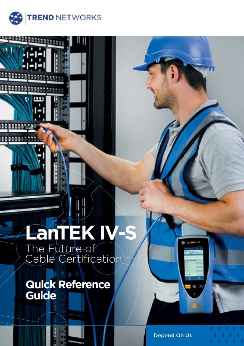
TREND NETWORKS
TREND NETWORKS LanTEK IV-S User manual
TREND NETWORKS
TREND NETWORKS VDV II User manual
TREND NETWORKS
TREND NETWORKS FIBERMASTER User manual

TREND NETWORKS
TREND NETWORKS SignalTEK 10G User manual

TREND NETWORKS
TREND NETWORKS VDV Series User manual
Popular Test Equipment manuals by other brands
Tektronix
Tektronix TDS1000B Series Operator's manual
GW Instek
GW Instek GDS-3000 Series Programming manual
Agilent Technologies
Agilent Technologies 8960 Manual operation
NEO TOOLS
NEO TOOLS 99-043 Original instruction manual
Keysight Technologies
Keysight Technologies i7090 Site Preparation
Steinberg Systems
Steinberg Systems SBS-LSG-001 user manual
