TREND NETWORKS VDV II User manual


1 VDV II 158800.02
VDV II
User Guide
Guide d’utilisation
Bedienungsanleitung
Guida utente
Manual de usuario
Guia do Usuário
用户指南
158800.02 (2020)
TREND NETWORKS
Stokenchurch House
Oxford Road
Stokenchurch
High Wycombe
Buckinghamshire
HP14 3SX UK
www.trend-networks.com

2VDV II 158800.02
© TREND NETWORKS 2020
The information contained in this document is the property of TREND NETWORKS and is
supplied without liability for errors a
nd omissions. No part of this document may be
reproduced or used except as authorized by contract or other written permission from
TREND
NETWORKS.
The copyright and all restrictions on reproduction and use apply to all media in
which this information may
be placed. TREND NETWORKS pursues a policy of continual
product improvement and reserves the right to alter without notice the specification, design,
price or conditions of supply of any product or service. All rights reserved.
Les informations dans ce document sont la propriété de TREND NETWORKS et elles sont
fournies sans responsabilité pour les erreurs et les omissions. Aucune partie de ce document
ne doit être reproduite ou utilisée, sauf en cas d’autorisation par contrat ou en cas d’autre
autorisation écrite donnée pa
r TREND NETWORKS Le copyright et toutes les limitations
concernant la reproduction et l’utilisation s’appliquent à tous les supports sur lesquels cette
information peut être placée.
TREND NETWORKS améliore continuellement ses produits et se
réserve le droit de modifier sans préavis la spécification, la conception, le prix ou les conditions
de fourniture d’un produit ou d’un service. Tous droits réservés.
Die Informationen in diesem Dokument sind das Eigentum von TREND NETWORKS und
werden ohne Gewährleistung der Vollständigkeit oder Korrektheit gegeben. Dieses Dokument
darf nur soweit vertraglich oder anderweitig schriftlich von
TREND NETWORKS Zugesichert
ganz oder teilweise vervielfältigt werden. Das Urheberrecht und alle Einschränkungen zur
Vervielfältigung und Nutzung gelten für alle Datenträger, auf denen diese Informationen
gespeichert werden können.
TREND NETWORKS bemüht sich um ständige
Produktverbesserungen und behält sich das Recht vor, die Spezifikation, das Design, den Preis
oder die Lieferbedingungen jeglicher Produkte oder Dienste ohne Vorankündigung zu ändern.
Alle Rechte vorbehalten
Le informazioni contenute nel presente documento sono di proprietà di TREND NETWORKS e
sono fornite senza alcuna responsabilità relativa a errori e omissioni. Sono vietati la
riproduzione o l'uso di tutto il documento o parte di esso, salvo se autorizzati da contratto o
permesso scritto di
TREND NETWORKS Il copyright e tutte le limitazioni sulla riproduzione e
l'uso si applicano a tutti i supporti nei quali le presenti informazioni possono essere contenute.
TREND
NETWORKS segue una politica volta al miglioramento continuo dei prodotti e si
riserva il diritto di modificare senza preavviso
le specifiche, il disegno, il prezzo o le condizioni
di fornitura di qualsivoglia prodotto o servizio. Tutti i diritti riservati.
La información que figura en este documento es propiedad de TREND NETWORKS, quien no
asume responsabilidad alguna sobre posibles errores u omisiones que puedan existi
r en este
documento. Queda prohibida la reproducción parcial o total de este documento, así como
darle un uso distinto al autorizado mediante contrato o autorización escrita por parte de
TREND
IDUSTRIES, independientemente del formato y soporte de los contenidos. TREND
NETWORKS
sigue una política de mejora continua del producto y nos reservamos el derecho
de modificar sin previo aviso las especificaciones, diseño, precio o condiciones de suministro
de cualquier producto o servicio. Todos los derechos reserv
ados.
As informações contidas neste documento são de propriedade de TREND NETWORKS e são
fornecidas sem responsabilidade sobre erros e omissões. Nenhuma porção deste documento
pode ser reproduzida ou usada exceto quando autorizada mediante contrato ou outra
permissão por escrito da
TREND NETWORKS. Os direitos de cópia e restrições de
reprodução
e uso são aplicáveis a todas as mídias nas quais estas informações possam ser colocadas. A
TREND
NETWORKS segue uma política de melhora contínua do produto e se reserva ao
direito de alterar sem aviso prévio as especificações, design, preço ou c
ondições de
fornecimento de qualquer produto ou serviço. Todos os Direitos Reservados.
English
Français
Deutsch
Italiano
Español
Português
中文
本文档所包含的信息是美国理想工业公司 (TREND NETWORKS) 的财产,对于本文档中出现的错误或遗
漏,提供方概不负责。除非得到美国理想工业公司的合同授权或其他书面许可,否则,本文档的任何部分均
不得复制或使用。版权和对复制和使用的所有限制都适用于本信息发布的一切媒介。美国理想工业公司奉行
持续改进产品的政策,并保留在不事先通知的情况下变更任何产品或服务的规格、设计、价格或供货条件的
权利。保留所有权利。

3 VDV II 158800.02
En
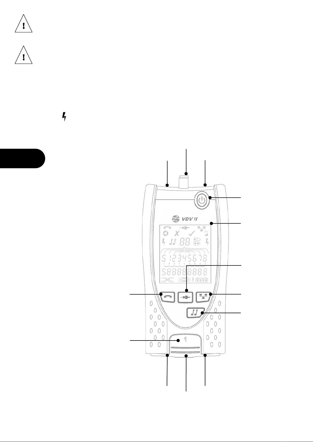
VOICE
(6 Pin RJ) port
VIDEO
(F-Coax) port
DATA
(8 Pin RJ) port
ON/OFF
button
Display
DATA port
selection
button
VIDEO port
selection
button
VOICE port
selection
button
TONE button
Dual Port
Remote Unit
Dual Port Remote Unit
VOICE port
Dual Port Remote Unit
DATA port
Storage for Coax
Remote Unit
WARNING!
Do not attach to AC power or telecoms cables carrying
>60volts. The VDV II Tester may be
damaged and cause a
safety hazard to the user.
CAUTION!
Improperly crimped, damaged or un
-
crimped plugs can damage
the ports on the VDV II Tester. Inspect plugs for proper
termination and crimping before inserting into the tester.
Contacts should always b
e recessed into the plastic grooves of
the plug. Only use 8
-Position plugs with the 8-Pin (DATA) port
and 6
-Position plugs with the 6-Pin (VOICE) port.
When
is displayed, disconnect immediately to avoid damage.

158800.02 VDV II 4
En
VOICE port
selected
VIDEO port
selected
DATA port
selected
Battery
Low
Indicator
POWER
To remove /
insert the battery:
•Remove the battery cover screw
and the battery cover from the
back of the tester.
•Remove / insert the battery,
taking care to connect correctly
and not to trap the cable.
•Replace the battery cover and
screw.
To switch the tester ON:
•Press the ON/OFF button
oThe display shows the
selected port (VOICE,
VIDEO or DATA).
o
If the Battery Low Indicator
is shown, the battery
should be replaced with a
new 9V battery.
To switch the tester OFF:
•Press the ON/OFF button.
TERMINATIONS
The Dual Port Remote Unit can be stored in the bottom end of the Tester, with
the jacks either inside for protection or outside for testing patch cables without
removing it from the Tester, and provides internal storage for the Coax Remote
Unit.
Termination
Number
Identifier
Indicator
Remote
Unit
Indicator
CONNECTIONS
To connect to a cable and to
confirm correct connection:
•Use the correct port (VOICE, VIDEO or DATA)
according to the cable connector type. (Use VOICE for
RJ11, RJ12, RJ14 or RJ25 cables, VIDEO for F 75 ΩCoax
or DATA for RJ45).
•Press the corresponding port button (VOICE, VIDEO or
DATA).
oThe display shows the selected port.
•
Connect one end of the cable to the selected port on the
tester and the other end to a Remote Unit for cable
identification and testing or to an Identifier for cable
identification only.
oThe display shows the type of terminatIon
(Remote Unit or Identifier) and its Number to
assist identification when a number of different
terminations are in use.
Dual Port Remote Unit
# 1 (Standard)
Coax Remote Unit
# 1 (Standard)
# 1 to 12 (Optional
-158053)
RJ45 Remote Unit
# 1 to 12 (Optional
-158050)
RJ45 Identifier
# 1 to 24 (Optional -
158051)
Battery cover
screw
Battery cover

5 VDV II 158800.02
En
CABLE TESTING
To test a cable:
•Connect the cable to the tester and to a suitable Remote Unit as described
above.
oCable testing runs
continuously (except if voltage is detected). There
is no need to start or stop the cable test.
Cable test results are shown using the two rows of numbers in the lower half of the
display. The top row of numbers refers to the pins at the near end. The num
bers
displayed, and S (Shield), depend on the port in use…
VOICE
– Pins 1, 2, 3, 4, 5 and 6 are shown
VIDEO
– S and Pin 1 are shown
DATA
– Pins 1, 2, 3, 4, 5, 6, 7 and 8 are shown. S is shown if the shield is connected.
The lower row of numbers refers to
the pins at the far end. The numbers displayed
show which pin at the far end is connected to which pin at the near end. Open
circuits and short circuits are shown. Multiple short circuits are shown in sequence.
Split Pair test:
!next to the Split Pair symbol shows when the test is disabled.
oWhen the Split Pair test is enabled, split pairs will cause the test to
fail.
oWhen the Split Pair test is disabled, split pairs will not cause the test
to fail.
To disable / enable the Split Pair test:
Shows when
Test Failed
Shows when
Test Passed
Shows that Shield and
Pins 1, 2 and 3 are
correctly connected
Shows that Pin 6 is
short circuit to Pin 7
Shows that Pin 8 is
disconnected
Shows when Split Pair
test is disabled
Shows that Pins 6 and 7
are short circuit
Shows when a crossover (uplink
cable) is detected (does not
cause the test to fail)
Shows that Pin 4 and
Pin 5 are reversed
Flashes when Split
Pair is detected
•Press and hold the port selection button of the currently selected port for 2
seconds to change the setting.
oThe Split Pair test is disabled or enabled
VOLTAGE DETECTION
If a voltage greater than approximately 2 volts is
detected onany pin(s), a Warning Indication is shown
and cable testing is not possible.

158800.02 VDV II 6
En
TONE GENERATION
VDV II can be used together with a compatible tone probe (available from
TREND) to
identify and trace cables. VDV II can generate various types of tone on various
combinations of pins. Choice of tone type a
nd pin connection is best determined by
experiment, to achieve the best results with a particular probe type and in a particular
cable situation.
To switch on the tone generation:
•Press the TONE button.
oThe currently selected tone type is generated on the currently
selected pins of the currently selected port.
oTone generation continues until switched off or for a maximum of 144
minutes.
To change the port that the tone is applied to:
•Press the relevant Port Selection button.
oThe tone is applied to the selected port using the tone type and pin
settings that were last used for that port.
ETHERNET DEVICE DETECTION
When the DATA port is selected, VDV II can detect the presence of an
Ethernet device connected to the DATA port
To change the pins that the tone is applied to:
•Press the Port Selection button of the currently
selected port.
oThe pins that the tone is applied to cha
nge each
time the button is pressed.
To change the tone type:
•Press the TONE button.
oThe tone type changes each time the TONE
button is pressed.
The tone generation can be controlled from the far end of
the cable, to assist in confirming that the
correct cable has
been traced.
To control the tone generation from the far end:
•Briefly apply a short circuit between any two wires of
the cable.
oThe sound of the tone changes.
To switch off the tone generation:
•Press and hold the TONE button.
oThe tone generation stops and normal cable
testing is resumed.
•Release the TONE button.
Shows the port
that the tone is
applied to
Shows tone
type
Shows pins that
tone is applied to
Shows that tone is
being generated
Shows Ethernet
device detected
DATA Port selected
Shows the pattern of short circuits
created by the Ethernet
transformers of the connected
switch port

7 VDV II 158800.02
Fr
Port VOIX
(Connecteur RJ, 6 contacts)
Port VIDÉO
(Connecteur coaxial, type F)
Bouton
ON/OFF
Ecran
Bouton de
sélection du
port DONNÉES
Bouton de
selection du
port VIDÉO
Bouton de
selection du
port VOIX
Bouton TONALITÉ
Unité distante bi-ports
Port VOIX de l’unité
distante bi-ports
Port DONNÉES de l’unité
distante bi-ports
Emplacement pour l’unité
distante coaxiale
AVERTISSEMENT!
Ne pas raccorder l'appareil à des câbles
d'alimentation ou à des câbles
téléphoniques sur lesquels est appliqu
ée une tension supérieure à 60 volts. Le
testeur VDV II pourrait être endommagé et entraîner un risque pour la sécurité
de l'utilisateur.
ATTENTION!
Des connecteurs mal sertis, non
-serti
s ou abîmés peuvent endommager les ports
du testeur VDV II. Vérifiez que les connecteurs sont des connecteurs adaptés (du
bon type) et qu'ils sont bien sertis avant de les raccorder au testeur. Les
contacts électriques doivent toujours être enfoncés dans l
es gorges en plastique
du connecteur. Utilisez uniquement des connecteurs à 8
contacts pour le port à
8
broches (DONNÉES) et des connecteurs à 6 contacts pour le port à 6 broches
(VOIX).
Lorsque
est affiché, débranchez immédiatement le VDV II pour éviter tout
dommage.
Port DONNEES
(Connecteur RJ, 8 contacts)

158800.02 VDV II 8
Fr
Port VOIX
sélectionné
Port VIDÉO
sélectionné
Port
DONNÉES
sélectionné
Voyant
« Batterie faible »
ALIMENTATION
Pour retirer / insérer la pile:
•Sur la face arrière du testeur,
dévissez la vis du compartiment
àpile puis retirez le,
•Retirez / insérez la pile et
raccordez-la en respectant les
polarités et en faisant attention à
ne pas coincer le câble.
•Remettez le cache du
compartiment à pile et revissez-
le.
Pour allumer le testeur:
•Appuyez sur le bouton ON/OFF
oL'afficheur indique le port qui
a été sélectionné (VOIX,
VIDÉO ou DONNÉES).
oSi le voyant « Batterie faible
»
s'allume, remplacez la
batterie par une batterie 9 V
Pour éteindre le testeur..:
•Appuyez sur le bouton ON/OFF.
Vis du cache du
compartiment à batterie
Cache du compartiment
à batterie
TERMINAISONS
L’unité distante bi-portspeut être rangée dans le compartiment situé au bas du testeur avec les
connecteurs orientés vers l'intérieur pour les protéger, ou vers l'extérieur pour y raccorder des
cordons à tester sans avoir à sortir la terminaison du testeur. L’unité distante c
oaxiale peut aussi être
logée dans le compartiment adapté.
Numéro de la
Terminaison
Voyant
indiquant la
présence
d'un
Identificateur
Voyant
indiquant la
présence
d’unité
distante
CONNEXIONS
Pour raccorder un câble
et confirmer que la connexion est correcte:
•Utilisez le port adapté (VOIX, VIDÉO ou DONNÉES) correspondant au
type de connecteur présent sur le câble. (Utilisez VOIX pour des câbles
RJ11, RJ12, RJ14 ou RJ25, VIDÉO pour des cables 75 ΩF coaxiaux F ou
DONNÉES pour des câbles RJ45).
•Appuyez sur le bouton du port correspondant (VOIX, VIDÉO ou
DONNÉES).
oL'afficheur indique le port sélectionné.
•Raccordez l'une des extrémités du câble au port choisi sur le testeur et
l'autre extrémité à une terminaison pour procéder à l'identification et au
test du lien ou bien raccordez le câble à un identificateur pour procéder
uniquement à une identification.
oL'afficheur indique le type de terminaison (Unité distante ou
Identificateur) et son numéro, pour aider à son repérage lorsque
plusieurs types de terminaisons différents sont présents.
Unité distante
bi-ports
Num. 1
(standard)
Unité distante coaxiale
Num. 1 (standard)
Num. de 1 à 12 (en option
-158053)
Unité distante RJ45
Num. de 1 à 12 (en
option - 158050)
Identificateur RJ45
Num. de 1 à 24 (en option -
158301)

9 VDV II 158800.02
Fr
DÉTECTION D'UNE TENSION
Si une tension supérieure à environ 2
V est détectée sur une ou plusieurs
broches, alors une alerte sonore est émise, un voyant d'avertissement s'affiche et
aucun test n’est possible.
TEST DU CÂBLE
Pour tester un cable:
•Raccordez le câble au testeur et à la Terminaison appropriée comme
décrit ci-dessus.
oLe test du câble s'effectue en continu (sauf lorsque l'appareil est en
Mode OUTILS ou si une tension est détectée). Il n'est pas nécessaire
d'initier ou d'arrêter le test du câble.
Le
s résultats du test du câble sont donnés à l'aide de deux lignes de chiffres
qui apparaissent dans la partie inférieure de l'afficheur. La ligne supérieure
correspond aux broches des connecteurs du testeur.
Les nombres affichés, ainsi que le «
S » (Blindage), dépendent du port en
cours d'utilisation:
Indique que le blindage (S) et que
les broches 1, 2 et 3
sont correctement raccordés
Indique que la
broche 6 est reliée à la
broche 7
Indique que la broche 8
n'est pas raccordée
S'affiche lorsque le test de
pairage est désactivé (split pair)
Indique que les broches 6
et 7 sont en court-circuit
Indique qu'un câble est croisé (lien montant) a été
détecté (n'entraîne pas l'échec du test)
Indique que les broches
4 et 5 ont été inversées
Clignote lorsqu'une paire mal
pairée est détectée (split pair)
S'affiche lorsque le test a échoué
S'affiche lorsque le test a réussi
Test de pairage (split pair):
! affiché à côté du symbole dépairage indique que ce test est désactivé.
oLorsque le test de pairage est activé, des paires mal pairées entraînent l'échec du test.
oLorsque le test de pairage est désactivé, les paires mal pairées n'entraînent pas l'échec du test.
Pour activer / désactiver le tes
t de pairage…
•Appuyez et maintenez enfoncé le bouton de sélection du port en cours d'utilisation pendant
2 secondes pour modifier les paramètres.
o
Le test de pairage est activé ou désactivé.
VOIX – Les broches 1, 2, 3, 4, 5 et 6 sont affichées
VIDÉO
– La broche 1 et « S » sont affichés
DONNÉES
– Les broches 1, 2, 3, 4, 5, 6, 7 et 8 sont affichées. « S » s'affiche
lorsque le bli
ndage est raccordé.
La ligne inférieure correspond aux broches de la terminaison. Les nombres
affichés indiquent à quelles broches de la terminaison sont raccordées les
broches du testeur. Les circuits ouverts et les courts
-circuits sont également
indiqués. Les courts-circuits multiples sont affichés séquentiellement.

158800.02 VDV II 10
Fr
ÉMISSION D'UNE TONALITÉ
VDV II peut être utilisé conjointement avec une sonde amplificatrice (disponible chez
TREND
en option) pour identifier et tracer des câbles. VDV II peut émettre
différentes tonalités en fonction de différentes combinaisons de broches. Le choix de
la tonalité et de la broche est guidé par l'expérience, de façon à obtenir les meilleurs
résultats pour un type de sonde donné et pour une situation particulière liée au
âbl
Pour activer l'émission d'une tonalité:
•Appuyez sur le bouton TONALITÉ.
oLe type de tonalité choisi est émis sur les broches sélectionnées du
port en cours d'utilisation.
oL'émission de la tonalité dure jusqu'à son extinction ou au maximum
pendant 144 minutes.
Pour modifier le port auquel s'applique la tonalité:
•Appuyez sur le bouton de sélection du port approprié.
oLa tonalité est activée pour le port désiré, le type de tonalité et la
séléction des broches sont ceux qui avaient été utilisés en dernier
pour ce port.
LA DÉTECTION DES PÉRIPHÉRIQUES ETHERNET
Lorsque le port DONNÉES est sélectionné, VDV II peut détecter la présence
d'un périphérique Ethernet raccordé au port DONNÉES
Pour modifier les broches auxquelles s'applique la tonalité:
•Appuyez sur le bouton de sélection du port en cours
d'utilisation.
oLes broches sur lesquelles la tonalité est
appliquée changent à chaque appui sur le bouton.
Pour modifier le type de tonalité:
•Appuyez sur le bouton TONALITÉ.
oLe type de tonalité change à chaque appui sur le
bouton TONALITÉ.
La tonalité peut être détectée à l'extrémité distante du
câble pour confirmer que le câble repéré est le bon.
Pour contrô
ler l'émission de la tonalité à partir de
l'extrémité distante...
•Mettez brièvement en court-
circuit deux conducteurs
quelconques du câble.
oLa mélodie de la tonalité change.
Pour désactiver l'émission d'une tonalité:
•Appuyez et maintenez enfoncé le bouton TONALITÉ.
Indique le port
auquel
s'applique la
tonalité
Indique le
type de
tonalité
Indique les broches
impactées par la
tonalité
Indique qu'une
tonalité est
émise
Indique qu'un périphérique
Ethernet a été détecté
Port DONNÉES sélectionné
Indique le schéma des courts-
circuits créés par les
transformateurs Ethernet du
port du switch raccordé
11 VDV II 158800.02
De
TELEFON
6 poliger RJ-Anschluss
VIDEO
F-Coax-Anschluss
DATEN
8-poliger RJ-Anschluss
EIN/AUS-
Taste
Display
Taste zur Auswahl des
TELEFON-Anschlusses
Dual-Port -
Remoteadapte
Dual-Port-Remoteadapter
TELEFON-Anschluss
Fach für Koaxial-
Remoteadapter
ACHTUNG!
Schließen Sie keine AC
-Netzspannungskabel oder Telekommunikationskabel
mit einer Spannung von mehr als 60 Volt an. Der Tester VDV II könnte
beschädigt und die S
icherheit des Anwenders gefährdet werden.
VORSICHT:
Nicht korrekt gecrimpte, beschädigte oder überhaupt nicht gecrimpte Stecker
können die Anschlüsse des Testers VDV II beschädigen. Prüfen Sie die Stecker
auf korrekte Anschlüsse und Befestigung
, bevor Sie diese in den Tester
einstecken. Die Kontakte sollten immer in die Kunststoffnuten des Steckers
eingelassen sein. Verwenden Sie ausschließlich 8
-polige Stecker für den 8-
poligen DATEN
-Anschluss und 6-polige Stecker für den 6-poligen TELEFON-
Ansc
hluss.
Wenn
angezeigt wird, trennen Sie sofort, um Schäden zu vermeiden.
Taste zur
Auswahl des
VIDEO-
TONGENERATOR
-Taste
Dual-Port-Remoteadapter
DATEN-Anschluss
Taste zur Auswahl
des DATEN-
Anschlusses

158800.02 VDV II 12
De
SPANNUNGSVERSORGUNG
Zum
Entnehmen/Einsetzen der Batterie:
•lösen Sie die Schraube der
Batteriefachabdeckung und heben die
Abdeckung von der Rückseite des Testers ab.
•entnehmen / setzen Sie die Batterie ein, wobei
darauf zu achten ist, dass die Anschlüsse korrekt
sitzen und kein Kabel eingeklemmt wird.
•
setzen Sie die Batteriefachabdeckung wieder auf
und ziehen Sie die Befestigungsschraube wieder
an.
Zum Einschalten des Testers:
•drücken Sie die ON/OFF-Taste.
oIm Display wir der ausgewählte Anschluss
angezeigt (TELEFON, VIDEO oder DATEN).
oWenn die Batteriewarnung eingeblendet
wird, sollten Sie eine neue 9-V-Batterie
einsetzen.
Zum Ausschalten des Testers:
•drücken Sie die ON/OFF-Taste.
Schraube der
Batteriefach-
Abdeckung
Batteriefach-
Abdeckung
TELEFON-
Anschluss
ausgewählt
VIDEO-
Anschluss
ausgewählt
DATEN-
Anschluss
ausgewählt
Batterie-
Warnung
Nummer
des
Abschlüsse
Identifier-
Symbol
Remote-
Adapter-
Symbol
Der Dual-Port-Remoteadapter lässt sich ander Unterseite des Testers einstecken. Die Buchsen
können zum Schutz nach innen oder zum Testen von Patchcords nach außen zeigen. Imletzteren
Fall muss der Remoteadapter zum Testen nicht aus dem Tester genommen werden. Außerdem
ermöglicht er die Aufnahme des Koaxial-Remoteadapters.
KABEL ANSCHLIESSEN
Zum Anschließen eines Kabels und Bestätigen der korrekten Verbindung:
•wählen Sie den richtigen Anschluss (TELEFON, VIDEO, DATEN)
entsprechend dem Kabelanschluss aus. (TELEFON: RJ11, RJ12, RJ14,
RJ25 / VIDEO: F 75 ΩKoaxialkabel / DATEN: RJ45).
•drücken Sie die Taste des gewünschten Anschlusses (TELEFON,
VIDEO, DATEN).
oDer gewählte Anschluss wird im Display angezeigt.
•Verbinden Sie ein Ende des Kabels mit dem ausgewählten Anschluss
am Tester und das andere Ende mit einem Remoteadapter zur
Kabelidentifikation und zum Testen oder mit einem Identifier nur
zum Identifizieren des Kabels.
oAuf dem Display werden die Art des Abschlusses
(Remoteadapter oder Identifier) sowie dessen Nummer
angezeigt, um die Erkennung zu erleichtern, falls mehrere
Abschlüsse verwendet werden.
Koaxial-Remoteadapter
Nr. 1 (Standard)
Nr. 1 bis 12 (optional -
158053)
RJ45-Remoteadapter
Nr. 1 bis 12 (optional -
158050)
Dual-Port-
Remoteadapter
Nr. 1 (Standard)
ABSCHLÜSSE
RJ45-Identifier
Nr. 1 bis 24 (optional -
158051)

13 VDV II 158800.02
De
KABELTESTS
Zum Testen eines Kabels:
•schließen Sie das Kabel an den Tester und an einen geeigneten Remoteadapter an (siehe
oben).
oDer Kabeltest wird kontinuierlich ausgeführt (außer im Einstellungsmodus oder wenn
eine Spannung erkannt wird). Es ist nicht nötig, den Kabeltest zu starten oder zu
stoppen.
Die Ergebnisse des Kabeltests werden in der unteren Display
-Hälfte in zwei Ziffernreihen
angezeigt. Die obere Zeile beschreibt die Pins am nahen Kabelende. Welche Nummern und ob
eine Schirmung (S) angezeigt werden, ist vom verwendeten Anschluss abhängig
.
TELEFON: Pins 1, 2, 3, 4, 5 und 6 werden dargestellt.
VIDEO: „S“ und Pin 1 werden dargestellt.
DATEN: Pins 1, 2, 3, 4, 5, 6, 7 und 8 werden dargestellt. „S“ wird nur angegeben, wenn eine
Schirmung angeschlossen ist.
Die untere Zeile beschreibt
die Pins am fernen Kabelende. Die angezeigten Nummern informieren
über die Zuordnung der Pins am fernen Ende zu den Pins am nahen Ende. Unterbrechungen und
Kurzschlüsse werden gekennzeichnet. Mehrere Kurzschlüsse werden nacheinander angezeigt.
Split-Pair-Test…
oEin Ausrufezeichen (!) neben dem Split-Pair-Symbol weist darauf hin, dass der Test
deaktiviert wurde.
oBei aktiviertem Split-Pair-Test führen aufgetrennte Adern dazu, dass der Test als Fehler
ausgegeben wird.
oBei deaktiviertem Split-Pair-Test haben aufgetrennte Adern keine Auswirkungen auf das
Testergebnis.
Zum Aktivieren/Deaktivieren
des Split-Pair-Tests…
•halten Sie die Anschlussauswahl-Taste des aktuell gewählten Anschlusses 2 Sekunden
lang gedrückt, um zwischen den Einstellungen zu wechseln.
oDer Split-Pair-Test wird aktiviert bzw. deaktiviert.
Angezeigt bei nicht
bestandenem Test
Angezeigt bei
bestandenem Test
Zeigt an, das die Schirmung
und Pins 1, 2 und 3 korrekt
angeschlossen sind.
Zeigt an, dass Pin 6 mit
Pin 7 verbunden ist.
Zeigt an, dass Pin 8 nicht
angeschlossen ist.
Wird angezeigt, wenn der Split-Pair-
Test deaktiviert wurde.
Zeigt an, dass Pin 6 und 7
kurzgeschlossen sind.
Zeigt eine gekreuzte Leitung im Uplink an
(ohne Auswirkung auf das Testergebnis).
Zeigt an, dass Pin 4 und
Pin 5 vertauscht sind.
Blinkt, wenn ein aufgetrenntes
Adernpaar (Split Pair) erkannt wurde.
SPANNUNGSERKENNUNG
Wenn an einem Pin eine Spannung von mehr als etwa 2 Volt erkannt wird, ein
Warnsymbol wird angezeigt und es sind keine Kabeltests möglic
h.

158800.02 VDV II 14
De
ETHERNET-GERÄTEERKENNUNG
Bei Auswahl des DATEN
-
Anschlusses erkennt der VDV II das Vorhandensein
eines mit dem DATEN
-Anschluss verbundenen Ethernet-Gerätes.
Zeigt den
Anschluss an,
an dem der
Ton erzeugt
Zeigt den
Tonsignaltyp an.
Zeigt die Pins
an, an denen
der Ton
erzeugt wird.
Zeigt an, dass der
Tongenerator
eingeschaltet ist.
Zeigt an, dass ein
Ethernet-Gerät erkannt
DATEN-Anschluss
ausgewählt
Zeigt das Muster der
Kurzschlüsse an, die von den
Ethernet-Übertragern des
angeschlossenen Switch-Ports
verursacht wurden.
TONGENERATOR
In Verbindung mit einem unterstützten induktiven Empfänger (erhältlich bei TREND) kann der VDV II
eingesetzt werden, um Kabel zu lokalisieren und zu identifizieren. Der VDV II kann an
unterschiedlichen Pin-Kombinationen verschiedene Töne erzeugen. Die genaue Zuordnung der
einzelnen Töne zu den Pins erfolgt am besten durch einfaches Ausprobieren, um die jeweils
genauesten Ergebnisse für die aktuell eingesetzte Kombination aus induktivem Empfänger und Kabel
herauszufinden.
Zum Einschalten des Tongenerators:
•drücken Sie die TONGENERATOR-Taste.
oDer aktuell ausgewählte Ton wirdanden aktuell ausgewählten
Pins des aktuell ausgewählten Kabels erzeugt.
oDer Tongenerator erzeugt die Töne bis zum Abschalten der
Funktion bzw. längstens 144 Minuten.
Zum Ändern des Anschlusses für den Tongenerator:
•drücken Sie die Anschlussauswahl-Taste des gewünschten
Anschlusses.
oDas Tonsignal wird an den ausgewählten Anschluss
angelegt. Es werden die Tonart und die Pins verwendet, die
für diesen Anschluss beim letzten Mal aktiviert worden
waren.
Zum Ändern der Pin
-Zuweisung für den Tongerator:
•drücken Sie die Anschlussauswahl-Taste des aktuell
ausgewählten Anschlusses.
oMit jedem Tastendruck wird die Pin-Zuordnung für den
Tongenerator geändert.
Zum Ändern des Tonsignals:
•drücken Sie die TONGENERATOR-Taste.
oMit jeder Betätigung der TONGENERATOR-Taste wird das
Tonsignal geändert..
Der Tongenerator kann vom fernen Ende des Kabels gesteuert
werden, um sich anhand des Tonsignals davon zu überzeugen, dass
das richtige Kabel gefunden wurde.
Zur Steuerung des Tongenerators vom fernen End
e des Kabels…
•schließen Sie kurz zwei beliebige Aderns des Kabels kurz.
oDas Tonsignal des Tongenerators ändert sich.
Zum Ausschalten des Tongenerators:
• halten Sie die TONGENERATOR-Taste gedrückt.

15 VDV II 158800.02
It
Porta VOCE
(RJ a 6 poli)
Porta VIDEO
(coassiale F)
Porta DATI
(RJ a 8 poli)
Pulsante di
accensione /
spegnimento
Display
Pulsante di
selezione
porta DATI
Pulsante di
selezione porta
VIDEO
Pulsante di
selezione porta
VOCE
Pulsante
TONO
Unità remota
doppia porta
Porta VOCE unità
remota doppia porta
Porta DATI unità
remota doppia porta
Vano per unità
remota coassiale
AVVERTENZA
Non collegare a cavi di alimentazione CA o da telecomunicazioni con una tensione
superiore a 60 volt. Il tester VDV II potrebbe danneggiarsi e causare un rischio
per
la sicurezza dell'utente.
ATTENZIONE
Spinotti crimpati scorrettamente, danneggiati o non crimpati possono causare il
guasto delle porte del tester VDV II. Prima dell'inserimento nel tester, controllare
che gli spinotti presentino
terminazioni e crimpaggio corretti. I contatti devono
sempre essere incassati nelle scanalature in plastica degli spinotti. Utilizzare
esclusivamente spinotti a 8 posizioni nella porta a 8 poli (DATI) e a 6 posizioni
nella porta a 6 poli (VOCE).
Quando vi
ene visualizzato , scollegare immediatamente per evitare danni.

158800.02 VDV II 16
It
Indicatore
Batteria
scarica
ALIMENTAZIONE
Per rimuovere / inserire la batteria:
•
Rimuovere la vite del coperchio del
vano batterie e il coperchio stesso
dalla parte posteriore del tester.
•Rimuovere / inserire la batteria,
facendo attenzione a collegarla
correttamente, senza intrappolare
il cavo.
•
Riposizionare il coperchio del vano
batterie e la relativa vite.
Per accendere il tester:
•Premere il pulsante di
accensione/spegnimento.
oIl display mostra la porta
selezionata (VOCE, VIDEO o
DATI).
oSe l'indicatore Batteri
a scarica è
attvo, occorre sostituire la
batteria con una nuova da 9 V.
Per spegnere il tester:
•Premere il pulsante di accensione/spegnimento.
TERMINAZIONI
L'unità remota doppia porta può essere riposta alla base del tester, lasciando i
connettori all'interno a scopo di protezione oppure all'esterno per consentire il
t
est dei cavi patch senza rimuoverli dal tester, e fornisce un vano interno per
l'unità remota coassiale.
Numero
terminazione
Indicatore
dell'identificatore
Indicatore
dell'unità
remota
Unità remota doppia
porta
N. 1 (standard)
Unità remota
coassiale
N. 1 (standard)
N. 1-12 (opzionale -
158053)
Unità remota RJ45
N. 1-12 (opzionale -
158050
)
Identificatore RJ45
N. 1-24 (opzionale -
158051)
COLLEGAMENTI
Per collegare un cavo e verificare la correttezza del collegamento:
•
Utilizzare la porta corretta (VOCE, VIDEO o DATI) in base al tipo
di connettore per cavi (utilizzare VOCE per cavi RJ11, RJ12, RJ14
o RJ25, VIDEO per cavi F 75 Ωcoassiali o DATI per cavi RJ45).
•Premere il pulsante della porta corrispondente (VOCE, VIDEO o
DATI).
oIl display mostra la porta selezionata.
•Collegare un'estremità del cavo alla porta selezionata sul tester e
l'altra estremità a un'unità remota per l'identificazione e il test
dei cavi oppure a un identificatore esclusivamente per
l'identificazione dei cavi.
oIl display mostra il tipo di terminazione (unità remota o
identificatore) e il relativo numero per assistere
nell'identificazione quando si utilizzano diverse terminazioni
allo stesso tempo.
Vite del coperchio
del vano batterie
Coperchio del
vano batterie
Porta VOCE
selezionata
Porta VIDEO
selezionata
Porta DATI
selezionata

17 VDV II 158800.02
It
TEST DEI CAVI
Per testare un cavo:
•Collegare il cavo al tester e a un'unità remota idonea come descritto in precedenza.
oIl test dei cavi viene
eseguito in continuo (tranne in modalità STRUMENTI o se si rileva
tensione). Non occorre avviare o arrestare il test dei cavi.
I risultati del test dei cavi vengono visualizzati utilizzando le due righe di numeri nella metà
inferiore del display. I numeri
della riga in alto si riferiscono ai poli all'estremità vicina. I numeri
visualizzati e "S" (Schermatura) dipendono dalla porta utilizzata...
VOCE
– Vengono visualizzati i poli 1, 2, 3, 4, 5 e 6
VIDEO
– Vengono visualizzati S e il polo 1
DATI
– Vengono visualizzati i poli 1, 2, 3, 4, 5, 6, 7 e 8. S viene visualizzato se è collegata la
schermatura.
I numeri della riga in basso si riferiscono ai poli all'estremità lontana. I numeri visualizzati
indicano le coppie di poli collegate alle due estremità. Vengono mostrati i circuiti aperti e i corto
circuiti. Se sono presenti più corto circuiti, vengono mostrati in sequenza.
Test delle coppie separate:
!accanto al simbolo della coppia separata mostra che il test è disattivato.
oQuando il test delle coppie separate è attivo, le coppie separate determinano
l'insuccesso del test.
oQuando il test delle coppie separate è disattivato, le coppie separate non determinano
l'insuccesso del test.
Per disattivare / attivare il test delle coppie separate:
•Premere e tenere premuto per 2 secondi il pulsante di selezione della porta scelta
attualmente, in modo da cambiare l'impostazione.
oIl test delle coppie separate viene disattivato o attivato.
Mostra che il
test non è
riuscito
Mostra che il
test è
riuscito
Mostra che il polo 6 è
collegato al polo 7
Mostra che il polo
8 è scollegato
Mostra che il test delle coppie
separate è disattivato
Mostra che i poli 6 e 7
sono in corto circuito
Mostra il rilevamento di un
crossover (cavo uplink) (non
determina l'insuccesso del test)
Mostra che i poli 4 e 5
sono invertiti
Lampeggia se viene rilevata una
coppia separata
Mostra che la schermatura e i poli
1, 2 e 3 sono collegati
correttamente
RILEVAMENTO DELLA TENSIONE
Se si rileva su qualsiasi polo una tensione superiore a circa 2 volt, visualizza
un'indicazione di avvertenza e mentre il test dei cavi non sono possibili.

158800.02 VDV II 18
It
Per attivare la generazione di toni:
•Premere il pulsante TONO.
oIl tipo di tono attualmente selezionato viene generato sui poli e la porta scelti al momento.
oLa generazione dei toni continua finché non viene disattivata o al massimo per 144 minuti.
Per cambiare la porta alla quale viene applicato il tono:
•Premere il pulsante di selezione della porta pertinente.
oIl tono viene applicato alla porta selezionata utilizzando le impostazio
ni del tipo di tono e dei
poli adottate l'ultima volta per tale porta.
RILEVAMENTO DEL DISPOSITIVO ETHERNET
Quando la porta DATI è selezionata, VDV II può rilevare la presenza di un
dispositivo Ethernet collegato a tale porta
Per cambiare i poli ai quali viene applicato il tono:
•
Premere il pulsante di selezione della porta per la
porta scelta attualmente.
o
I poli ai quali viene applicato il tono cambiano
ogni volta che si preme il pulsante.
Per cambiare il tipo di tono:
•Premere il pulsante TONO.
oIl tipo di tono cambia ogni volta che si preme
il pulsante TONO.
È possibile controllare la generazione di toni
dall'estremità lontana del cavo, in modo da verificare
più facilmente che sia stato tracciato il cavo corretto.
Per controllare la generazione di toni dall'estremità
lo
ntana:
•Applicare rapidamente un corto circuito tra due
fili qualsiasi del cavo.
oIl suono del tono cambia.
Per disattivare la generazione di toni:
•Premere e tenere premuto il pulsante TONO.
Mostra la porta
alla quale è
stato applicato
il tono
Mostra
il tipo di
tono
Mostra i poli ai
quali è stato
applicato il tono
Mostra che il
tono viene
generato
Mostra il dispositivo
Ethernet rilevato
Porta DATI
selezionata
Mostra lo schema di
corto circuiti creato dai
trasformatori Ethernet
della porta di
commutazione collegata
GENERAZIONE DI TONI
VDV II è utilizzabile insieme a una sonda a toni compatibile (disponibile da
TREND
) per identificare
e tenere traccia dei cavi. VDV II può generare vari
tipi di toni su diverse combinazioni di poli. Per
scegliere il tipo di tono e il collegamento dei poli il metodo migliore è procedere per tentativi, fino
a ottenere risultati ottimali con un tipo specifico di sonda in una particolare situazione di cablagg
io.

19 VDV II 158800.02
Es
Tecla de selección
de puerto
de DATOS
Tecla de selección
de puerto
de VÍDEO
Tecla de selección
de puerto
de VOZ
Puerto de VOZ
(RJ de 6 pines)
Puerto de DATOS
(RJ de 8 pines)
Puerto de VÍDEO
(coaxial F)
Tecla
ON/OFF
Pantalla
Tecla TONO
Puerto de VOZ de
unidad remota doble
Puerto de DATOS de unidad
remota doble puerto
Almacenamiento
para unidad remota
coaxial
Unidad
remota doble
ADVERTENCIA
No conecte el
comprobador a cables de telecomunicaciones o alimentación
CA de más de 60 voltios. Podría dañarse el comprobador VDV II y suponer un
peligro para la seguridad del usuario.
ATENCIÓN
Conectores dañados, deteriorados o mal crimpados pueden dañar los puertos
del comprobador VDV II. Compruebe que los conectgores estén en buen
estado antes de insertarlos en el comprobador. Los contactos deben quedar
siempre por dentro de las ranuras de plástico de la toma. Utilice solo
conectores de 8 posiciones con el puerto de
8 pines (DATOS RJ45) y
conectores de 6 posiciones con el puerto de 6 pines (VOZ RJ11).
Cuando se muestra
, desconecte inmediatamente para evitar daños.
This manual suits for next models
2
Table of contents
Languages:
Other TREND NETWORKS Test Equipment manuals

TREND NETWORKS
TREND NETWORKS FiberTEK IV User manual

TREND NETWORKS
TREND NETWORKS SignalTEK 10G User manual

TREND NETWORKS
TREND NETWORKS FIBERMASTER User manual

TREND NETWORKS
TREND NETWORKS LanTEK IV User manual

TREND NETWORKS
TREND NETWORKS LanTEK IV-S User manual

TREND NETWORKS
TREND NETWORKS VDV Series User manual


