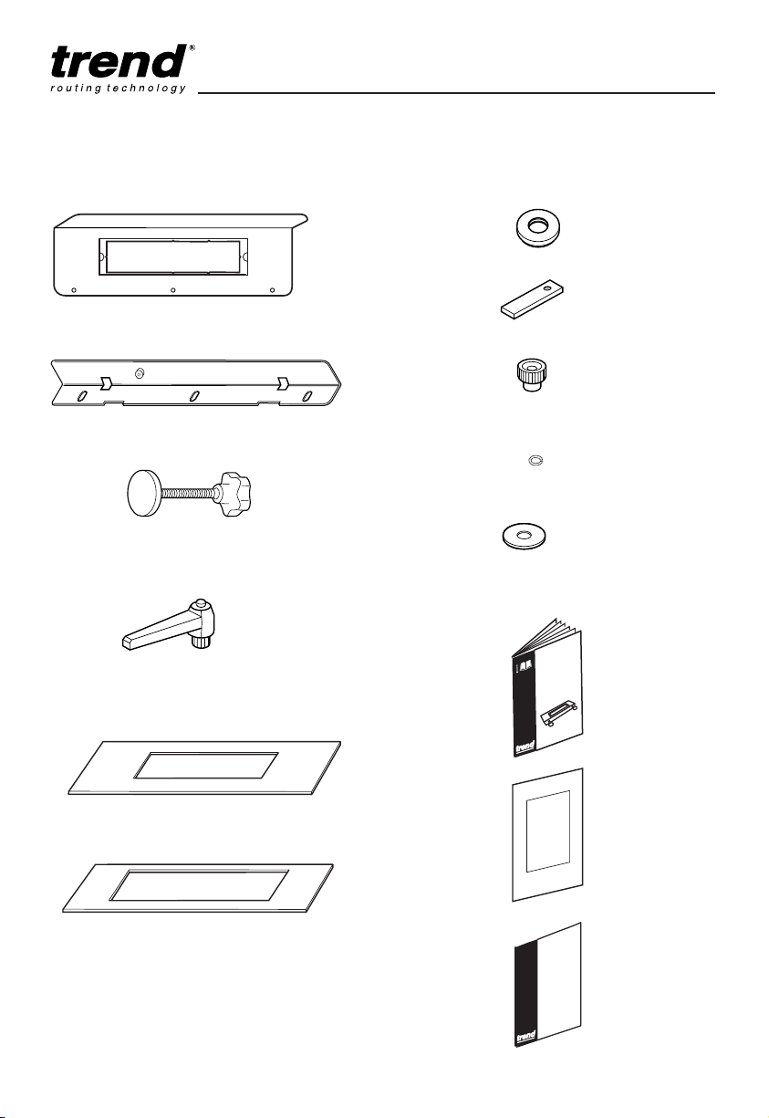
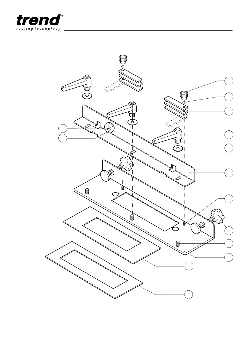
LOCK JIG
-2-
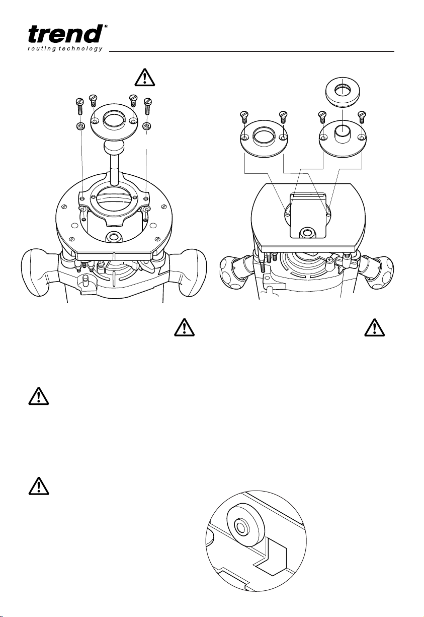
SAFETY
Observe the safety regulations in the
instruction manual of the Power Tool to
be used or connected to this
attachment. Also observe any
applicable additional safety rules. Read
the following safety instructions before
attempting to operate this product.
PLEASE KEEP THESE
INSTRUCTIONS IN A SAFE
PLACE.
The attention of UK users is drawn to
The Provision and Use of Work
Equipment Regulations 1998, and any
subsequent amendments.
General
■Disconnect power tool, when not in
use. Before servicing and when
changing accessories such as
cutters. Disconnect power tool and
attachment from power supply.
Ensure the machine is switched off
before plugging tool in or
connecting to a power supply.
■Always mount the power tool,
accessory or attachment in
conformity with the present
instructions.
■Keep children and visitors away. Do
not let children or visitors touch the
tool, accessory or attachment.
Keep children and visitors away
from work area.
■Make the workshop child proof with
padlock and master switch.
■Dress properly. Do not wear loose
clothing or jewellery, they can be
caught in moving parts. Rubber
gloves and non-skid footwear is
recommended when working
outdoors. Wear protective hair
covering to contain long hair.
■Consider working environment. Do
not use the product in the rain or in
a damp environment. Keep work
area well lit. Do not use power tools
near gasoline or flammable liquids.
Keep workshop at a comfortable
temperature so your hands are not
cold.
■The accessory or attachment must
be kept level and stable at all
times.
■Keep work area clean. Cluttered
workshops and benches can cause
injuries
■Use the attachment with the power
tools and accessories specified in
this manual only. Do not force the
tool or attachment to do a job for
which it is not designed.
■Secure idle tools. When not in use,
tools should be stored in a dry and
high or locked up place, out of
reach of children.
■For best control and safety use
both hands on the power tool and
attachment. Keep both hands away
from cutting area. Always wait for
the spindle and cutter to stop
rotating before making any
adjustments.
■Always keep guards in place and in
good working order.
■Remove any nails, staples and
other metal parts from the
workpiece.
■Maintain tools and cutters with
care. Keep cutters sharp and clean
for better and safer performance.
Do not use damaged cutters.
Follow instructions for lubricating
and changing accessories. Keep
handles dry, clean and free from oil
and grease.
■Maintain accessories. Do not use
damaged accessories. Only use
accessories recommended by the
manufacturer.
■Check damaged parts. Before
operation inspect the attachment,
the power tool, the cable, extension
cable and the plug carefully for
signs of damage. Check for
alignment of moving parts, binding,
breakage, mounting and any other
conditions that may effect its
operation. Have any damage
repaired by an Authorised Service
Agent before using the tool or
accessory.
■Do not use tool if switch does not
turn it on or off. Have defective
switches replaced by an Authorised
Service Agent.
■Don't over reach. Keep proper
footing and balance at all times.
■Don’t abuse the cable. Never carry
power tool or accessory by cord or
pull it to disconnect from the
socket. Keep cord from heat, oil
and sharp edges. Always trail the
power cord away from the work
area.
■Connect dust extraction equipment.
If devices are provided for the
connection of dust extraction and
collection facilities, ensure these
are connected and properly used.
■Check all fixing and fastening nuts,
bolts and screws before use to
ensure they are tight and secure.
Periodically check when machining
over long periods.
■Stay alert. Watch what you are
doing. Use common sense. Do not
operate tools when you are tired,
under the influence of drugs or
alcohol.
■Personal Protective Equipment
(PPE). All PPE must meet current
UK and EU legislation.
■Do not leave tools running
unattended. Do not leave tool until
it comes to a complete stop.
■Always clamp workpiece being
machined securely.
Routing Safety
■Disconnect router power tool.
When not in use, before servicing
and when changing accessories
such as cutters, disconnect router
and attachment from power supply.
■Ensure router cutter has stopped
rotating before changing it. Never
use the spindle lock as a brake.
■Remove adjusting keys and
spanners. Form the habit of
checking to see that keys and
adjusting spanners are removed
from the router tool, cutter and
attachment before turning router
on. Make sure cutter can rotate
freely.
■Check all ball bearing and blade
fixing screws before use to ensure
they are tight and secure.
Periodically check when machining
over long periods.
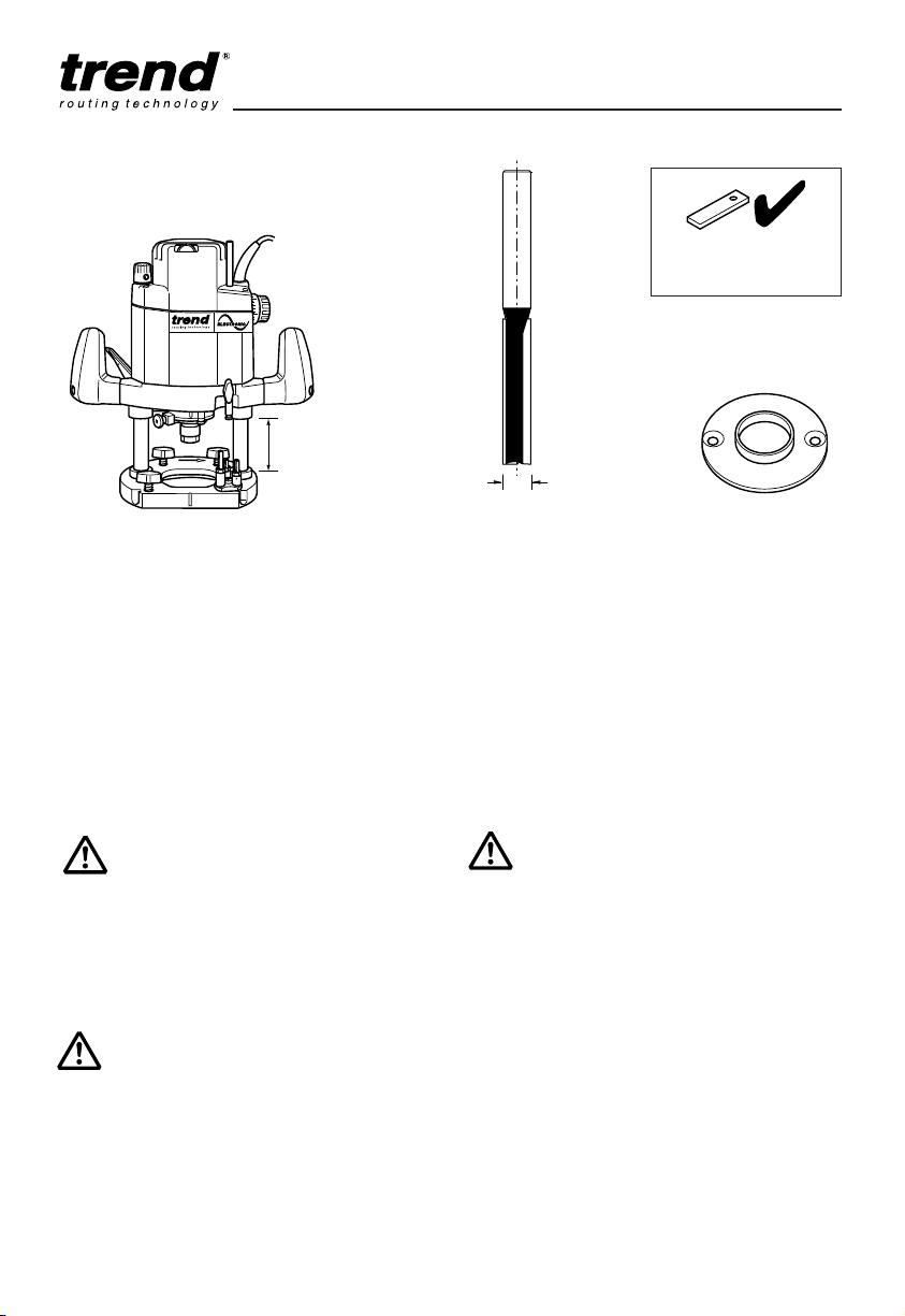
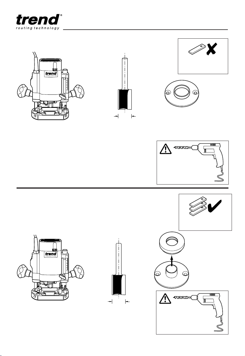
■When using a template guide bush
ensure it cannot come into contact
with collet and nut.
■Noise. Take appropriate measures
for the protection of hearing if the
sound pressure of 85dB(A) is
exceeded. Routing sound pressure
may exceed 85dB(A), so ear
protection must be worn.
■Eye protection. Wear safety
goggles, spectacles or visors to
protect the eyes from ejected
waster particles.