REF. CRB
Thank you for purchasing this Trend accessory
which should give lasting performance if used in
accordance with these instructions.
The following symbols are used throughout these
instructions.
Denotes risk of personal injury, loss
of life or damage to the tool in case of
non-observance of the instructions.
Refer to the instruction manual of your
power tool.
This unit must not be put into service until it has
been established that the power tool to
be connected to this unit is in compliance with
2006/42/EC (identified by the CE marking on
the power tool).
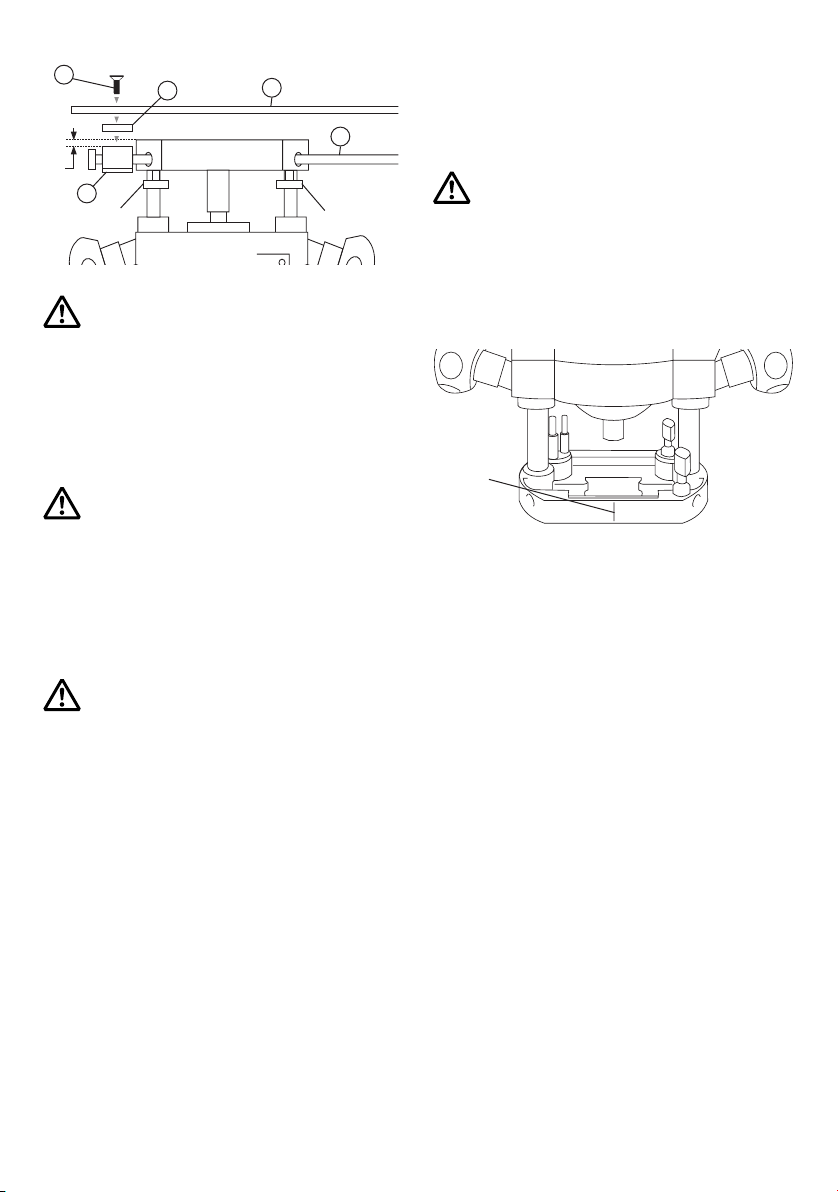
INTENDED USE
This accessory is a retro fit, quick change, multi-
functional router base for use with routers that will
accept two 8mm diameter rods at centres of 78mm
to 130mm. It is intended to:
nIncrease the overall versatility of the router.
nImprove the quality of finish of every routing pass.
nReduce the possibility of error.
nIncrease stability during routing.
nIncrease the level of precision achieved.
nSave set up time between tasks.
nMaximum cutter diameter for use on offset base
is 40mm. Max.diameter depends on router used.
(Please check router manual specifications).
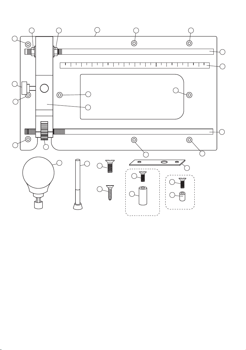
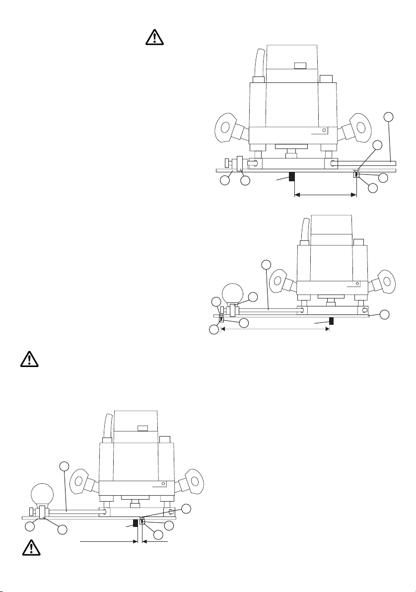
Features
1. Offset baseplate.
2. Router compass radius 19mm to 224mm.
When measured from outside edge of hole.
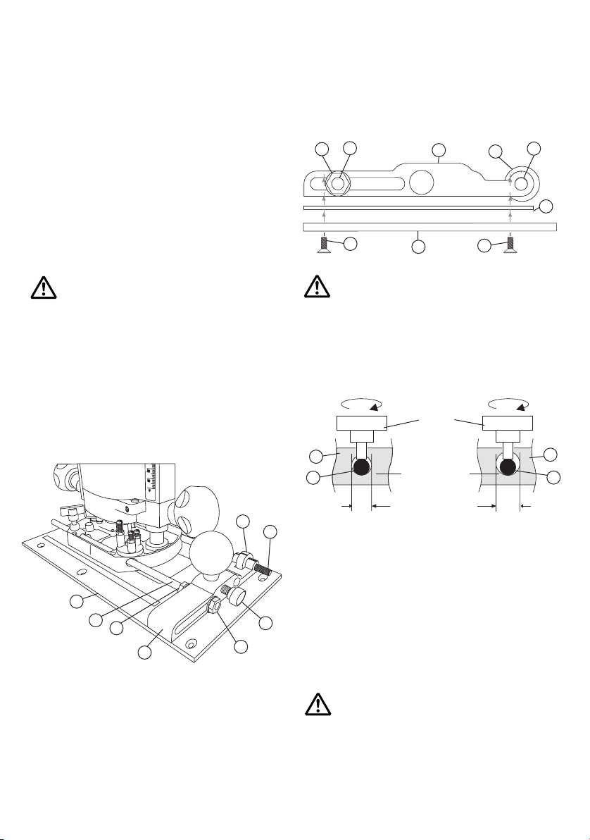
3. Adjustable trenching with a clamp guide.
4. Adjustable anti-tilt support.
(Max. 80mm, min. 8mm).
5. Adjustable offset mortising
(Material 50mm to 200mm).
6. Adjustable false panel groove copier.
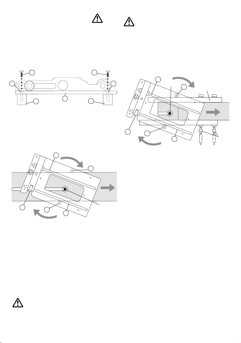
7. Using the CRB with euro style guide bush
fitting routers with the Varijig and a long
series guide bush.
8. Lateral adjustment 110mm, with 40 micro
adjustment (one revolution equals 1.25mm).
Note: All dimensions shown are based on a T5
router being used with a 6.3mm (1/4”) diameter
cutter.
COMBINATION ROUTER BASE
-1-
ITEMS REQUIRED
nRouter with suitable rod diameters
and centres.
nRouter cutter.
nClamps.
n13mm A/F open ended spanner x 2.
nHand tools.
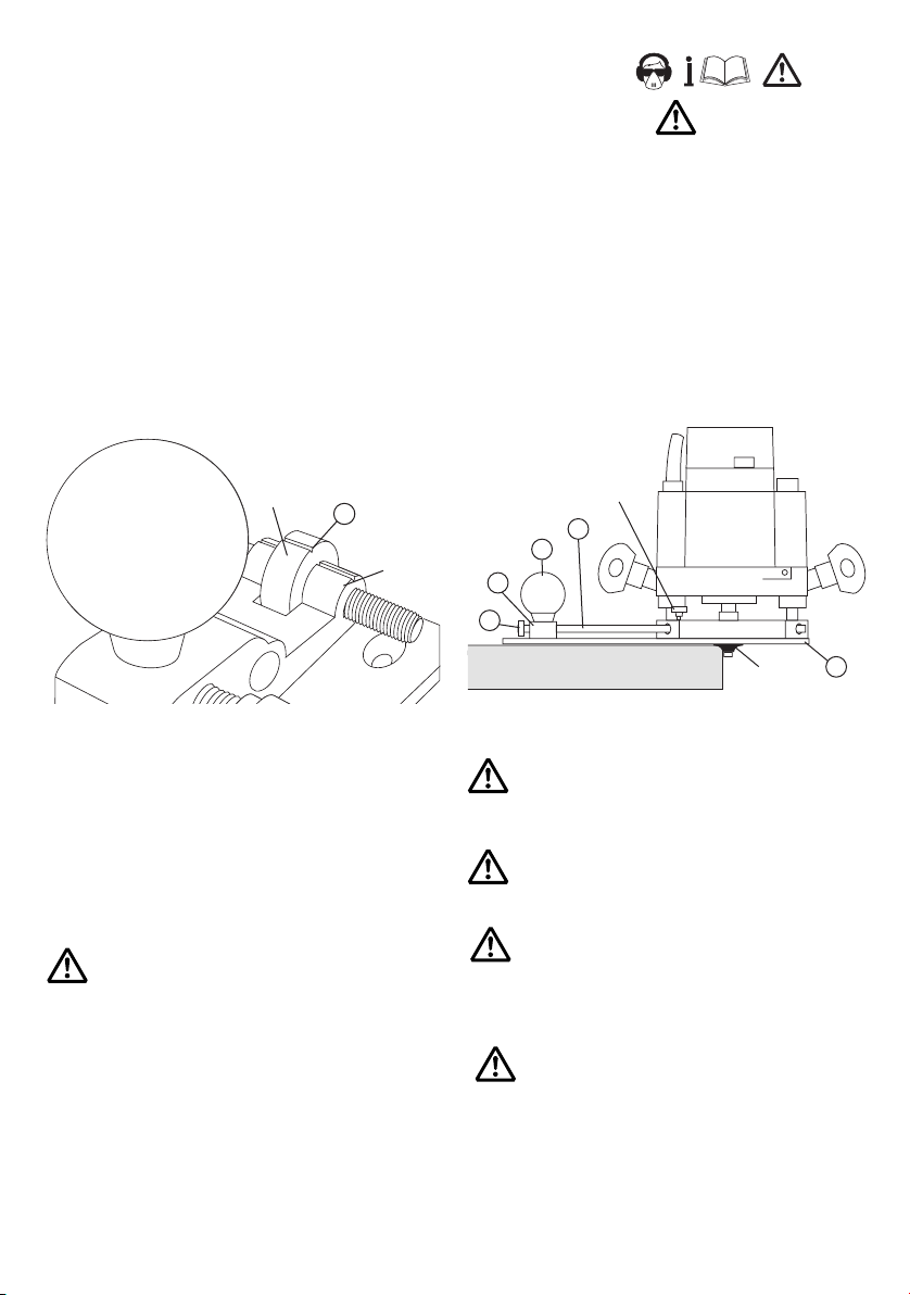
SAFETY
Please read and understand the safety
points at the end of this instruction as
well as the power tool instructions before
use.
PLEASE KEEP THESE INSTRUCTIONS
IN A SAFE PLACE.
The attention of UK users is drawn
to The Provision and Use of Work
Equipment Regulations 1998, and any
subsequent amendments. Users should
also read the HSE/HSC Safe Use of
Woodworking Machinery Approved Code
of Practice and Guidance Document and
any amendments.
Users must be competent in using
woodworking equipment before using our
products.
Ensure working position is comfortable.
Please keep children and visitors away
from tools and work area. All tools will
have a residual, risk, so must therefore
be handled with caution.
Only use tooling that meets EN847-1/2
safety standard and any amendments.