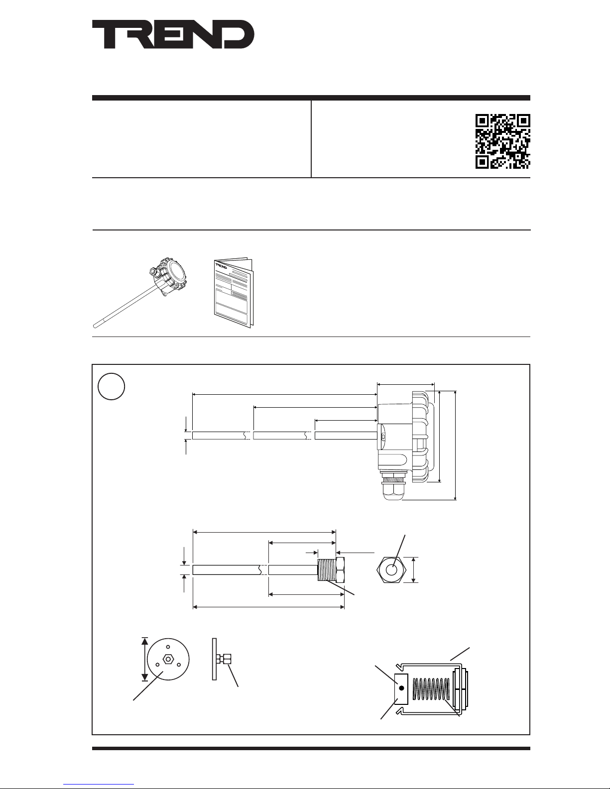
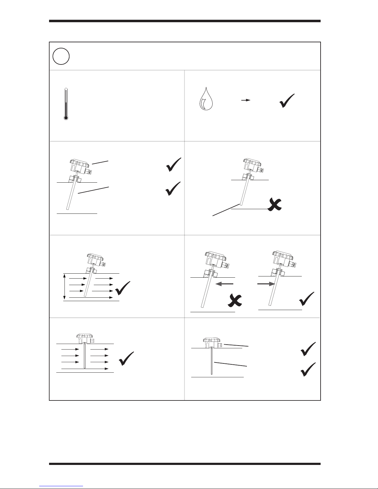
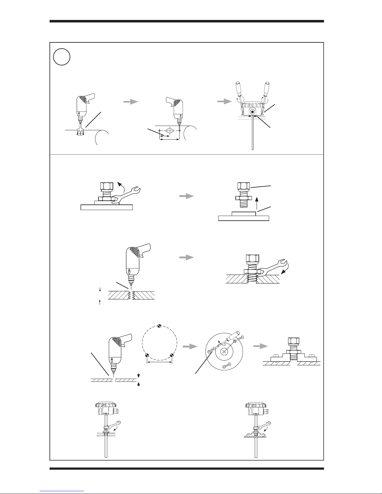
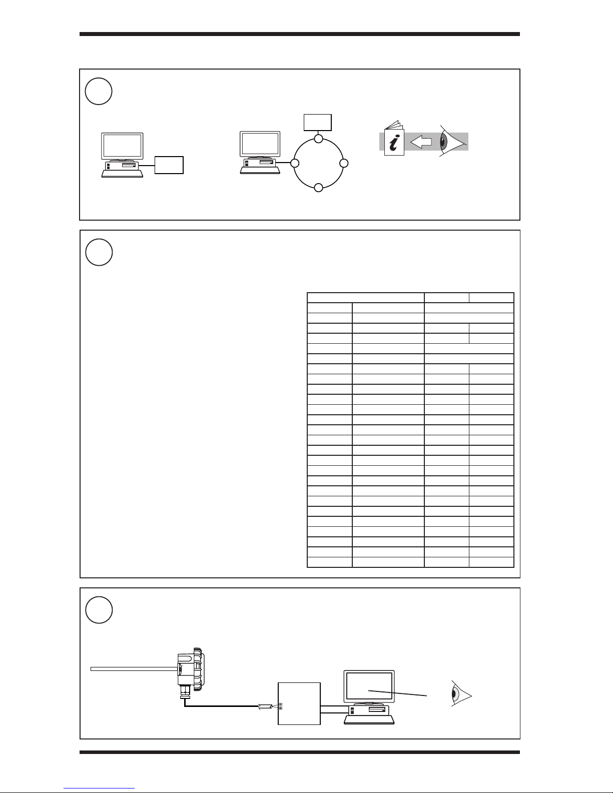
TREND Thermistor TBTI User manual
Other TREND Temperature Controllers manuals


Popular Temperature Controllers manuals by other brands


P.W. KEY
P.W. KEY rt-208gt operating manual

BH Thermal
BH Thermal BriskONE owner's manual

West Control Solutions
West Control Solutions KS 45 Operation Notes

MCS
MCS RITC-15B Operator's manual

SMC Networks
SMC Networks Thermo-con INR-244-639 Operation manual

eltherm
eltherm Ex-TC It Series operating instructions

Omron
Omron C200H-TV Series Operation manual

industrie technik
industrie technik CA1 instructions

KRAL
KRAL EET 32 operating instructions

dixell
dixell XR420C Installing and operating instructions

Opt Lasers
Opt Lasers TEC-8A-24V-PID-HC operating manual

Vaillant
Vaillant VR 92/3 Operating and installation instructions