eltherm Ex-TC It Series User manual

eltherm GmbH
Ernst-Heinkel-Straße 6 -10
57299 Burbach, Germany
T.: +49 2736 4413-0
F.: +49 2736 4413-0
BU 122-It
www.eltherm.com
Ex-TC/..-It
Assembly and Operation
Ex-TC/A-It; Ex-TC/AL-It Ex-TC/M-It
OPERATING
INSTRUCTIONS

2
www.eltherm.com 2
Operating instructions
Ex – Temperature Controller Ex-TC/…-It
BU 122-It
Revision 2
eltherm GmbH
Ernst-Heinkel-Str. 6-10
57299 Burbach
T.: +49 2736 4413-0
F.: +49 2736 4413-50
Document:
BU - 122-It
Installation and Operation of
Ex-TC/…-It
Autor Peter Schmidt
Revision: 210.02.2022_dm 30.10.2019
Reservation
We reserve the right to make technical changes. Changes, errors and misprints do not justify any no claim for compensation. For safety com-
ponents and systems, the installation instructions and the relevant standards and regulations must be observed.

3
www.eltherm.com 3
www.eltherm.com
DESCRIPTION & TECHNICAL DATA
DESCRIPTION
MODEL OVERVIEW
MODEL VIEWS
TECHNICAL DATA
EXPLOSION PROTECTION
CERTIFICATION
STANDARDS
LABELLING
SPECIAL CONDITIONS
SAFETY INSTRUCTIONS
INCOMING GOODS
STORAGE
SCOPE OF DELIVERY
MOUNTING
INSTALLATION
CONNECTING THE CONTROLLER
INSTALLING THE CONTROLLER
ALARM & SETPOINT SETTINGS
COMPLETING THE INSTALLATION
OPERATION & MAINTENANCE
OPERATING STATES
SETTINGS
4
4
4
4
5
6
6
6
6
6
7
7
7
7
8
10
11
11
12
13
13
14
14
Particularly important points in these instructions are marked by symbols:
important information and instructions for safe, effective and
environmentally compatible use.
NOTE
i
indicates an potential dangerous situation. If it is not
avoided, there is a risk of damage or malefunction.
CAUTION
WARNING
indicates a dangerous situation. If it is not avoided,
there is a risk of injury or at least a high risk of damage.
DANGER
indicates an extremely dangerous situation. If it is not
avoided, there is a danger to life or at least a high risk of serious injury.

174 mm
266 mm
128 mm
153 mm
4
www.eltherm.com 4
Operating instructions
Ex – Temperature Controller Ex-TC/…-It
BU 122-It
Revision 2
DESCRIPTION & TECHNICAL DATA
DESCRIPTION
The electronic temperature controller Ex-TC/…-It is part of an eltherm family of microcontroller-supported electronic temper-
ature controllers and limiters. It is designed for operation with electrical trace heating systems and can be used to maintain
temperatures and for frost-protection applications in areas subject to explosion hazard. The control keys and sensor connections
are designed to be intrinsically safe.
All models have a sturdy plastic housing to IP 65 and a mounting base flanged onto the housing that is optimally suited for
mounting pipelines. Depending on the intended purpose, the Ex-TC/... is available as a temperature controller with alarm relay,
temperature controller including RS 485 interface with Modbus protocol or a controller/limiter combination with alarm relay.
The Ex-TC/...-It is able to switch high nominal currents and with its round shape it ensures optimum mechanical safety. The cover
closes quickly with a snap lock, making it easy to handle where it is used. All variants are suitable for use with our self-regulating
heating cables (ELSR) and resistance heating cables (ELK, ELP).
MODELL ARTIKELNUMMER TYP ALARM BUS
Ex-TC / A- It 0X60101 Controller (with collective alarm) x
Ex-TC / AL- It 0X60121 Controller and limiter (with collective alarm) x
Ex-TC / M- It 0X60131 Controller (with Modbus connection) x
MODEL OVERVIEW
MODEL VIEWS

5
www.eltherm.com 5
www.eltherm.com
TECHNICAL DATA
HOUSING / MOUNTING STAND
Material Polyamide, non-conductive, UV-resistant
IP protection type IP 65
Cable entries for mounting base 1x at, 1x round
Line dimensions Ø 3-5 mm (sensor)
4.0x11 mm - 5.5x14 mm (heating cable - suitable for ELSR-H, -LS,-N, -SH, -SHH)
Permitted jacket materials TPE min. 0.7 mm; uoropolymer min. 0.4 mm
Max. width of strap 16 mm
Possible pipe diameters ≥ 20 mm
Interference immunity min. 7J
Ground approx. 1.5 kg
CONTROLLER
Nominal voltage 230 ± 10% V AC, 50 Hz
Nominal load
Single pole
Max. 25 A (+ 40 °C) T6 with connecting line >= 2.5 mm²
Max. 20 A (+ 50 °C) T6 with connecting line >= 2.5 mm²
External fuse protection 25 A (20 A)
Power consumption approx. 5 VA without load
Sensor connection
Intrinsically safe 2-wire connection (jumper required between terminals 2 and
3) or
3-wire connection with automatic conductor compensation up to max. 20
Relay output for collective alarm (not /M) 1 N/O contact 3 A, 250 VAC, 100 VA or 5 A, 24 VDC, 100 W
MODBUS (/M only) RS485 RTU (max. 120 devices), Um = 6Vmax
Temperature unit °C
Measuring range -99 ... 450 °C
Setpoint range 1 ... 450 °C (T1), factory setting: 5 °C
Undertemperature alarm (not /L) 1 ... 450 °C, factory setting: 0 °C
Overtemperature alarm (/AL only) 1 ... 450 °C, factory setting: 0 °C
Switching accuracy <2 K
Hysteresis <100 °C: 3 K
>100 °C: 3 %
Setpoint setting One rotary knob each for hundreds, tens and ones place (0...9)
Connection cross-sections 0.2 ... 4 mm²
Terminal tightening torque 0.6 ... 0.8 Nm
Intrinsically safe measuring circuit (maximum values) U=2.5V, I=36.8mA, P=40mW, R=155 ohms
Max. capacitance 44 mH 10 mH 1 mH 100 mH 10 mH 1 mH
Max. inductance 1.2 F 7.1 F 14 F 28 F 65 F 110 F
Adapter -20°C up to +100°C
Mounting base -20°C up to +200°C
Housing (depending on screw connection) -45°C up to +50°C
Controller (depending on load) -55 °C to +40 °C / +50 °C
OPERATING TEMPERATURE
eltherm GmbH, Ernst-Heinkel-Str. 6-10, 57299 Burbach
Type: Ex-TC/...-It Art-No.: Serial-No.:
II 2G Ex eb ib mb IIC T5/T6 Gb; II 2D Ex ib tb IIC T100°C/85°C Db
IBExU20ATEX1015X
Ex eb ib mb IIC T5/T6 Gb; Ex ib tb IIIC T100°C/T85°C Db
IECEx IBE 20.0002X
230V / 50Hz 25A (-40°C...+40°C) / 20A (-40°C...+50°C)
Do not open while explosive Atmosphere present!
eltherm GmbH Burbach Ex-It
II 2G Ex eb IIC Gb II 2D Ex tb IIIC Db
IBExU09ATEX1023U, IECEx IBE12.0024U
6
www.eltherm.com 6
Operating instructions
Ex – Temperature Controller Ex-TC/…-It
BU 122-It
Revision 2
SPECIAL CONDITIONS according to TYPE EXAMINATION CERTIFICATE
DANGER
• An overvoltage category I/II/III in accordance with IEC 60664-1 is permitted for the“MODBUS“ and“power supply” circuits.
• The power circuit must have external fuse protection with max. 25 A (40 °C) or 20 A (50 °C).
• The intrinsically safe Pt100 sensor that is connected can also be viewed as a simple electrical component in accordance with
sensor 5.7 of
IEC 60079-11.
• Ambient temperature range: -40°C to 40°C (25 A) and -40°C to 50°C (20 A)
• The minimum ambient temperature depends on which cable entries, reductions and sealing plugs
are used and may vary.
• Mounting permitted exclusively with mounting base“eltherm It”
• Only cable entries, reductions and sealing plugs of ignition protection type “e”or “t” with EPL Gb or Db may be used. They must
be tted with a sealing ring, O-ring or shaped sealing
elements.
• For operation at ambient temperatures > 40°C or with currents > 20A, the connection cables with cross-sections of at least 2.5
mm² must be used.
• The cable entries must be checked to ensure they are suitable for the connecting line provided.
• In addition to an overcurrent protective device, a FI circuit breaker in conformity with EN 60079-30-1
must be installed in TT or TN systems. For more information see the assembly and operating instructions of the connected heat
tracing system.
• Safe and reliable operation of the device is only ensured if the technical operating parameters are observed (including nominal
voltage, switching capacity and ambient temperature, etc.).
• It is not possible for the user to repair the device.
• The manufacturer shall not be liable for damage resulting from improper use or external inuences. Unauthorised changes to
the device will furthermore void any warranty claims as well as conformity with Directive 2014/34/EU.
• Measurements of the insulation resistance can be conducted if necessary after the device fully disconnected from the mains
power. The measurement must be made between the voltage connection and load connection with maximum 1000V.
LABELLING MOUNTING STAND
LABELING HOUSING
EXPLOSION PROTECTION
ATEX II 2G Ex eb ib mb IIC T5/T6 Gb
II 2D Ex ib tb IIIC T100°C...T85°C Db
IEC-Ex Ex eb ib mb IIC T5/T6 Gb
Ex ib tb IIIC T100°C...T85°C Db
CERTIFICATION
IBExU20ATEX1015X
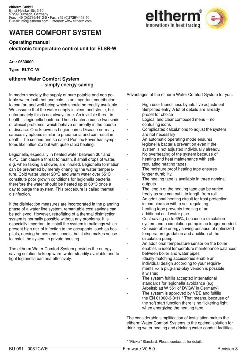
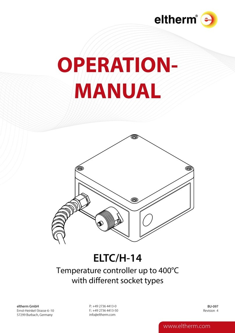
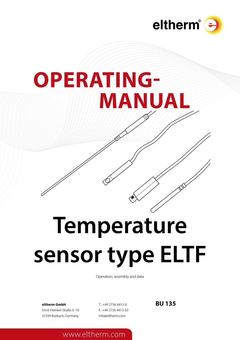
IECEx IBE 20.0002X
STANDARDS
EN IEC 60079-0:2018
EN 60079-7:2016; EN 60079-11:2012; EN 60079-18:2015

1
23
5
2
4
3
5
7
www.eltherm.com 7
www.eltherm.com
Ex-TC/M-It
POS Art.No. TYPE
Tighten-
ing
torque
[Nm]
Clamping
range
2 2576020058 Screw connection
M20x1.5 2,30 4-13
3 2572580009 Reduction
M25x1.5/M20x1.5 3,00
4 2576025050 Screw connection
M25x1.5 3,00 2x7,2-8
5 2576025092 Screw connection
M25x1.5 5,00 9-17
SCOPE OF DELIVERY
Ex-TC/A-It & Ex-TC/AL
POS Art.No. TYPE
Tighten-
ing
torque
[Nm]
Clamping
range
1 2576020056 Plug
M20x1.5 2,00
2 2576020058 Screw connection
M20x1.5 2,30 4-13
3 2572580009 Reduction
M25x1.5/M20x1.5 3,00
5 2576025092 Screw connection
M25x1.5 5,00 9-17
The connection sets required for
safely and properly connecting the eltherm ELSR
heating cables are not included with delivery.
NOTE
i
INCOMING GOODS
Check the controller and accessories when the goods are re-
ceived and compare the data on the type plate with the data
on the delivery slip to make certain the correct materials have
been delivered.
STORAGE
Store in a dry environment at an ambient temperature of 0°C
to 50°C.
the applicable regulations. This manual is intended for
that group of persons and contains all important infor-
mation required for working safely with Ex-TC control
devices.
• The manual must be retained with the system docu-
mentation
for later use and must be kept and made available
throughout the entire service life of the product.
• Mounting of the Ex-TC/...It should only be carried
out by persons trained in working with Ex devices.
• Strict compliance with the applicable safety
requirements in areas subject to explosion hazard
is a precondition for the safety of persons, systems
and devices.
• The persons tasked with planning, installation and
maintenance have a special responsibility and
must therefore be familiar with the exact details of
SAFETY INSTRUCTIONS
ATTENTION
ALARM
POWER
SUPPLY
or
BUS
POWER
SUPPLY

2
TX 20
500 mm
200 mm 200 mm
8
www.eltherm.com 8
Operating instructions
Ex – Temperature Controller Ex-TC/…-It
BU 122-It
Revision 2
MONTAGE
ATTENTION
When selecting the mounting
location, take into account the degree of mechanical
hazard for the terminal housing as well as the IP
protection type and the permitted operating temperature.
RECOMMENDED TOOLS
REQUIRED WRENCH SIZES
Fitting Wrench sizes
[mm]
M20x1.5 23, 24
M25x1.5 24, 29
1Do not fasten heating cable and sensor line at the planned
measurement point approx. 500 mm.
2Prepare the end of the sensor line with a strong wire and
by using adhesive tape to lead a sensor line into the mount-
ing base.
4Cut o the end
of the heating cable
at an angle of about 45°.
2Lead a sensor line
into the opening pro-
vided and
pull it about 200 mm
into the mounting
base.
3Remove the adhe-
sive tape and strong
wire from the sensor
line.
5Guide the heat-
ing cable into the
mounting stand.
6Guide the heat-
ing cable about
200 mm through
the mounting
stand.
MOUNTING ON THE PIPE

9
www.eltherm.com 9
www.eltherm.com
7Fasten the mount-
ing stand onto the
pipe with a strap.
8Mount the heating cable
connection (not included
with delivery of Ex-TC).
PREPARATION FOR THE ELECTRICAL CONNECTION
2Insert a at-tip
screwdriver between the
locking arm and the
rear bar and
push the locking arm for-
ward a few millimetres by
turning the screwdriver
3Turn the headless
screw back with the Allen
wrench (size 2) until it is
protruding slightly
out of the locking arm.
OPENING THE HOUSING
1Tighten the headless
screw with an Allen
wrench (size 2) until the
locking arm is ush with
the side bars
4Raise the
cover (using
the-screwdriver)
5 Open the
cover (using
the-screwdriver)
REMOVING THE CONTROLLER
6 Loosen retaining
screws
7Slide controller
out of the locking
mechanism

10
www.eltherm.com 10
Operating instructions
Ex – Temperature Controller Ex-TC/…-It
BU 122-It
Revision 2
8Remove controller
from the housing
9Guide the heating
cable and sensor line
into the housing.
10 Insert the hous-
ing into the mounting
base until the holder is
resting completely
on the mounting base
and the housing has
audibly engaged.
Guide the cable for the power supply
and alarm/bus (depending on the model) into the
screw connections provided (see“Scope of Delivery”).
Do not tighten the screw connections yet.
NOTE
i
INSTALLATION
WARNING
Before starting work on
heating or connection cables, or on
connection terminals, make certain the relevant power
circuit is turned o and protected against being turned
on again unintentionally
• Then check all the parts of the Ex-TC as well as any seals
and O-rings in or on it to make certain they are clean and
not damaged
• All the cables that are inserted must be laid permanently
in place
• Connecting threads can be tted with suitable reduc-
tions. Reductions must not be nested
• Follow the order of assembly without exception!
• Guide a cable of the correct type and tted appropriately
into the housing. Do not tighten the cable glands yet.
• Prepare the cable ends for mounting (strip them)
• Connect the power supply and the temperature sensor to
the corresponding terminals on the controller (see connection
diagram, section “CONNECTING THE CONTROLLER”).
• Do not connect the heating cable yet.
• Tighten the terminals nger-tight (torque between 0.6 and 0.8
Nm).
DANGER
Make certain there is no explosive
atmosphere present and that none can occur.
Then turn on the power supply and make the settings
as described in section “ALARM & SETPOINT SET-
TINGS”page 11.
Retain the settings that are made in the
system documentation.
NOTE
i
CLICK

0
CONTROLLER
TEMPERATURE
Ex-TC/A
LOW
ALARM
LED
x1
x10
x100
0
0
Ex ib
PE1
230 VAC
20A 55°C
25A 40°C
PE1
L
N
N0
L0
PE2+3
250 VAC 3A
24 VDCA 5A
PE3 PE2 PE1
CONTROLLER
TEMPERATURE
Ex-TC/AL
LOW
ALARM
LED
x1
x10
x100
0
0
0
PE1
230 VAC
20A 55°C
25A 40°C
PE1
L
N
N0
L0
PE2+3
250 VAC 3A
24 VDCA 5A
0
0
0
LIMITER
TEMPERATURE
HIGH
ALARM/
RESET
0
CONTROLLER
TEMPERATURE
Ex-TC/M
LOW
ALARM
LED
x1
x10
x100
0
0
Ex ib
PE1
230 VAC
20A 55°C
25A 40°C
PE1
GND
D-
D+
L
N
N0
L0
PE2+3
11
www.eltherm.com 11
www.eltherm.com
• De-energize the circuit again and
connect all signal and sensor lines as well as the heating
cables to the corresponding terminals
• Tighten the terminals nger-tight (torque between 0.6
and 0.8 Nm)
• Tighten unused terminals as well
• Push the controller back into the lower position of the
slotted holes and tighten the retaining screws (see fol-
lowing page“INSTALLING THE CONTROLLER” page 11).
• Close all openings (covers, threaded holes, cable entries).
Take into account the torques in the
“TECHNICAL DATA”section.
• Tightening the cable entries too tightly can adversely
aect the IP protection type!
CONNECTING THE CONTROLLER
PE TERMINALS (for all Ex-TC devices)
Ex-TC/AL-It
Ex-TC/A-It
Ex-TC/M-It
INSTALLING THE CONTROLLER
1Slide controller into the locking mechanism. Tighten
retaining screws. Move the cable into its nal position and
tighten the cable glands

CONTROLLER
TEMPERATURE
LOW
ALARM
LED
x1
x10
x100
5
2
1
LIMITER
TEMPERATURE
HIGH
ALARM/
RESET
12
www.eltherm.com 12
Operating instructions
Ex – Temperature Controller Ex-TC/…-It
BU 122-It
Revision 2
ALARM & SETPOINT SETTINGS
ATTENTION
Theoretical setting range 999°C.
Max. permitted setting range < 450°C!
Controller reset
button
Setting example
(all models)
Ones
Tens
Hundreds
e.g. 125°C
Limiter reset
button
First set the limiters (alarm values), then the controllers
(setpoints).
When powering on, switch the limiters in the
Ex-TC/AL devices to“on”if there are no errors present
and the ACTUAL temperature is below the
limiter SETPOINT values.
NOTE
i
Factory setting: 5°C
After the alarm settings have been completed, set the tem-
perature setpoint. Use the blue rotary knobs of the controller
to select the desired setpoint.
The selected value can be seen in a recess at the edge of the
rotary knob. Values outside of the setting range (> 450) will be
indicated by a ashing LED alternating between green and
red. Temperature control remains inactive for this time.
Factory setting: 0°C
After the alarm settings have been completed, set the maxi-
mum temperature for the limiter.
The selected value can be seen in a recess at the edge of the
rotary knob.
Factory setting: 0°C
Press the reset button of the limiter and hold it until the LED
ashes green.
Set the desired upper temperature limit with the blue rotary
knobs of the controller
The selected value can be seen in a recess at the edge of the
rotary knob.
To conrm press the reset button until the LED goes out.
Then the desired temperature setpoint must be set again.
• After 100 seconds the setting menu closes
automatically without any values being saved.
Setting the temperature setpoint (Ex-TC/It-A, -AL and -M)
Setting the maximum temperature (Ex-TC/It-AL)
Setting the overtemperature alarm (Ex-TC/It-AL)
Factory setting: 0°C
Press and hold the reset button of the controller until the LED
ashes green. Set the desired upper temperature limit with
the blue rotary knobs of the controller (labelled with CON-
TROLLER TEMPERATURE).
The selected value can be seen in a recess at the edge of the
rotary knob.
To conrm press the reset button (LOW ALARM) until the LED
goes out.
• After 100 seconds the setting menu closes
automatically without any values being saved.
Then the desired temperature setpoint must be set again.
Setting the undertemperature alarm
(Ex-TC/It-A, -AL and -M)• Disconnect the Ex-TC/M from the power supply
• Set the temperature adjustment buttons to 9 9 9 and
connect Ex-TC/M to the power supply -> LED ashes
green quickly
• Set the Modbus address with the temperature setting
buttons (hundreds / tens / ones)
• Conrm the setting with the reset button -> LED ashes
more slowly and is then lit continuously.
• Disconnect the Ex-TC/M from the power supply
• Connect the Ex-TC/M to the power supply, set the tem-
perature setpoint and place the device in operation.
MODBUS SETTINGS (Ex-TC/It-M)
Make note of the settings
made on page 14.
NOTE
i

13
www.eltherm.com 13
www.eltherm.com
The following value are transferred by bus:
1. Data word Controller IS value, HI, LO
2. Data word Controller REF value, HI, LO
3. Data word Controller Undertemperature alarm
value, HI, LO
4. Data word Controller error
Sensor error 0x01 0000 0001
Undertemperature alarm 0x02 0000 0010
Measuring range error 0x04 0000 0100
MODBUS SETTINGS (Ex-TC/It-M)
SUPPORTED MODBUS PROTOCOL FUNCTIONS
Code MODBUS function Register Action
03h READ HOLDING
REGISTERS 4xxxx
Read setpoints and error
messages from control-
lers and limiters
08h DIAGNOSTIC Function test of slaves
10h WRITE MULTIPLE
REGISTERS 4xxxx
Send setpoints
to controllers
and limiters
MODBUS PARAMETERS
MASTER-SLAVE application Ex-TC/M
Interface RS485
Format RTU
Start bit 1
Data bit 8
Stop bit 1
Transmission rate 9600 baud
Parity None-parity
Slave ID 1...120
COMPLETING THE INSTALLATION
CLOSING THE HOUSING
1Visual inspection of housing and cover to ensure they are
not damaged. Cover can only be inserted in one position
(locking arms / twist protection recesses have dierent
width). Move the cover to the appropriate position.
2Attach the cover with the narrower locking arm (without a
headless screw), close the cover and…
3Use the pliers to lock the cover
OPERATION & MAINTENANCE
• Observe the locally applicable safety regulations when the Ex-
TC is in operation
• Comply with the permitted operating conditions in accordance
with the“TECHNICAL DATA”section and the labelling . (type/
dimensions of lines, pipe diameter, operating conditions, IP
protection type).
DANGER
• If the temperature setpoint needs to be checked,
rst make certain that there is no explosive atmos-
phere present and that none can occur.
• Then connect the power supply and open the
housing cover.
• Instead of the Pt100 sensor, connect a Pt100
simulator and check the switching function of the
controller.
• After the check is complete, reconnect the Pt100
sensor and close the cover.
WARNING
The junction box may only be
opened (this also includes loosening cable entries!)
when it is disconnected from the power supply.

14
www.eltherm.com 14
Operating instructions
Ex – Temperature Controller Ex-TC/…-It
BU 122-It
Revision 2
• Conduct a visual inspection at suitable intervals to ensure
the Ex-TC is undamaged and securely seated in consider-
ation of the installation location and application.
• Retighten the cable entries if necessary. Damaged parts
must be replaced by qualied personnel
• Protect the Ex-TC devices against damage in the event of
OPERATING STATES (all models)
LED state Cause Contact setting
Flashes red
Controller: Recorded temperature
below the limit for undertempera-
ture alarm
Limiter: Recorded temperature
above the limit for overtempera-
ture alarm
Load contact closed
Alarm contact opened
Flashes red and green Setpoint set to 000,
Controller expects setpoint entry
load contact opened, alarm contact opened; for /AL model:
Load contact opened and locked (can be manually reset by
pressing the reset button after eliminating the sensor problem;
status saved for possible power failure)
Continuous red (model /
AL only)
Recorded temperature above
set maximum temperature
Load contact opened and locked (can be manually reset by
pressing the reset button after safe temperatures are restored;
status saved for possible power failure), alarm contact opened
Continuous green Recorded temperature below
setpoint Load contact closed, alarm contact closed
Flashes green Device is in
setting mode Load contact opened, alarm contact closed
SETTINGS
COMMISSIONING MAINTENANCE / CHANGE
Temperature setpoint
Undertemperature alarm
Maximum temperature
Overtemperature alarm
MODBUS address
Date
Signature
repair work to heated system parts.
• After repair work is complete, check the EX-TC again
(visual inspection).
• Do not operate damaged Ex-TC devices.

15
www.eltherm.com 15
www.eltherm.com
NOTES

eltherm GmbH
Headquarters
Ernst-Heinkel-Straße 6 -10
57299 Burbach. Germany
T.: +49 2736 4413-0
F.: +49 2736 4413-50
www.eltherm.com
8643050X601X1-BU-122-It Operating instructions Ex – Temperature Controller Ex-TC/…-It EN
DISPOSAL
The WEEE logo indicates that this product must not be disposed of with residential waste.
Further information about disposal and recycling of old electrical and electronic devices and where
to find collection points is available from your local disposal company or from the manufacturer
from which you bought the product.
NOTE
i
This manual suits for next models
3
Table of contents
Other eltherm Temperature Controllers manuals

eltherm
eltherm ELTC-W User manual

eltherm
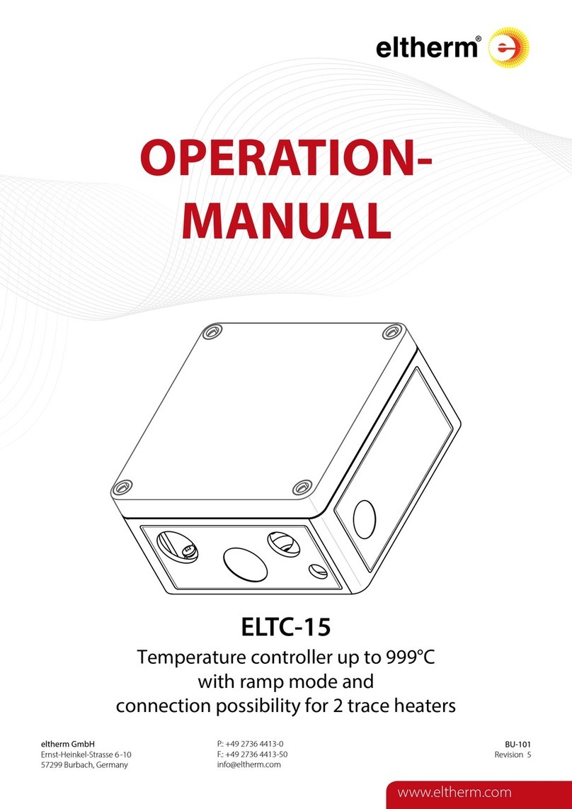
eltherm ELTC-14P User manual

eltherm
eltherm ELTC-15 User manual

eltherm
eltherm ELTC/L-15 User manual

eltherm
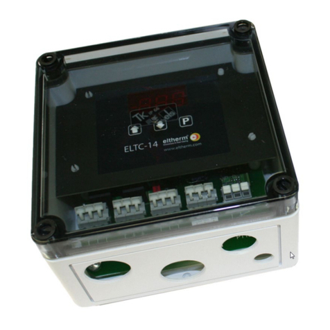
eltherm ELTC-14 User manual

eltherm
eltherm ELTC-14 User manual

eltherm
eltherm ELTC-41 User manual

eltherm
eltherm ELTC/L-15 User manual

eltherm
eltherm ELTC-15 User manual

eltherm
eltherm ELTC/H-14 User manual