LUNAdMB
Swegon reserves the right to alter specications. 08/04/2021
Data communication
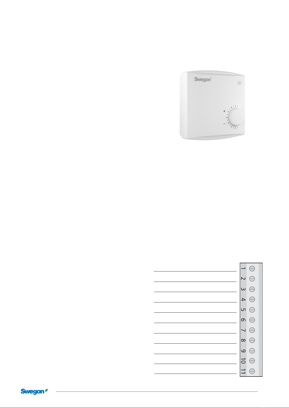
The room controller has a built-in communication port
that enables connection to an RS 485 network with
Modbus for supervising and overriding via a building
management system, for example a computer.
6.1 Modbus protocol
Modbus is a communication protocol (language) used to
transfer information between a server and a number of
client nodes.
All “traffic” on the network is always initiated only by the
server node.
All other nodes on the network are only permitted to sit
quietly and wait for the server to “query” just them. Thus
the clients cannot send their own packages to any other
client node.
In addition, a client node cannot send spontaneous
messages to the server, for example, alarms or the like.
Regular reading from the server is established instead, so
that it can detect alarms out in the client nodes.
6.1.1 Modbus RTU protocol
Modbus RTU, which is one of the different variants of the
Modbus protocol, is used to communicate with the room
controller.
Other “dialects” available (but which are not supported by
the room controller) are Modbus ASCII and Modbus TCP.
6.1.2 Data bits and bytes
The information on the Modbus network is structured by
a long row of ones and zeros. These are called bits and
are grouped into bytes (= characters). Each byte appears
like this:
a) start bit (1 bit)
b) data bits 0–7 (8 bits)
a) stop bit (1 bit)
Other byte structures can be selected with the help of a
room controller E201 with display or E203. 7 or 8 data
bits can be selected, and 1 or 2 stop bits. An extra parity
bit precisely before the stop bit can also be selected to
give extra error detection.
6.1.3 Data rate
The room controller is preset at the rate 19200 bits/sec.
Other rates can be selected with the help of a room
controller with display (or configuration unit). If the data
rate is changed to a higher level, higher demands are
made on the network cable. You may need to limit the
cable length and sometimes even choose a shielded cable.
Termination of the cable ends may also be necessary at
higher rates to eliminate reflection interference.
6.1.4 Modbus RTU package
Every “package” (message) sent on the network includes
the following information:
a) node address (1 byte)
b) command (1 byte)
c) data values (1–252 bytes)
d) checksum (2 bytes/CRC-16)
When a complete package with bytes has been sent from
the server, the queried node has the possibility to send its
response back to the server.
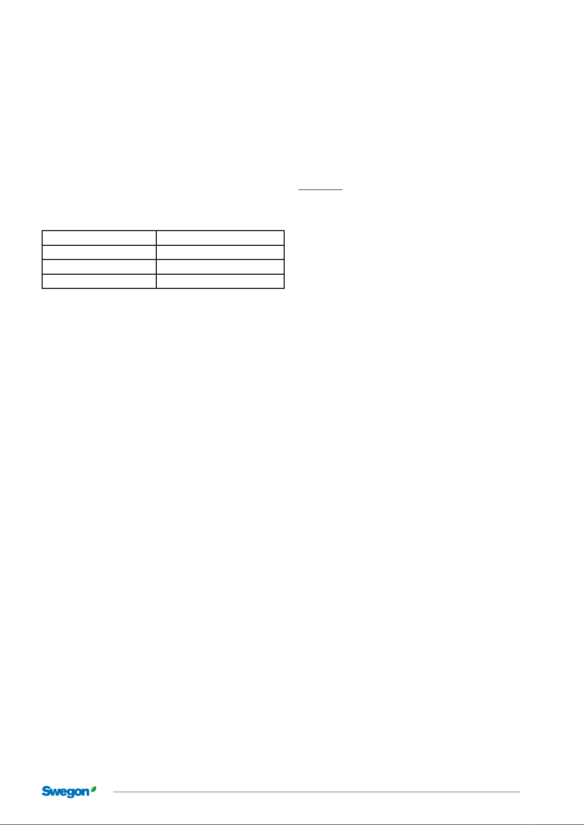
6.1.5 Modbus address
Each Modbus device needs its own unique address to
be able to communicate on the network. This is called a
node address and should be a number between 1 and
247. The node address is set on the room controller’s
circuit board, on an 8 position dip switch.
Exercise care to ensure that no Modbus device has the
same number as another device on one and the same
segment (bus). It is therefore a good idea to create a list
of node numbers that shows in which room each device
is installed.
If you choose to set the address on the dip switch, you need
to calculate binary code. Each button corresponds to a
value that is twice the size of the previous button. The first
button means 1, next button 2, next 4, next 8 and so on.
Example:
ON
1 2 3 4 5 6 7 8
The row of buttons above is called a “dip switch” and
has the buttons 2, 5 and 6 set to the “ON” position. The
buttons are in turn worth 1, 2, 4, 8, 16, 32, 64 and 128. If
a button is in the “ON” position, you should calculate the
button value. The example above means that the address
50 is selected.
(0+2+0+0+16+32+0+0 = 50)
In order to quickly calculate the right binary code, you
can use certain mini calculators (which have the binary
number system). The calculator included with Microsoft
Windows can be set to “advance mode”, and then used
to convert common decimal numbers to binary. Note
that you must then reverse the order of ones and zeros.
The number shown to the far right of the calculator
should always be set on the button to the far left on the
controller’s dip switch. If the calculator shows fewer than
eight digits, this means that the rest of the buttons to the
right on the dip switch should be set to the off position
(i.e. not “ON”).