TRI-TECH MEDICAL MCP100A Manual

- 1 -
Tri-Tech
Medical Inc.
Manufacturer of
Medical Gas Pipeline Equipment
Installation & Operating Instructions for
Area,
Master &
Combination
Alarm Systems

- 3 -
Tri-Tech
Medical Inc. Table of Contents
Contents
Introduction---------------------------- 5
Features & Benefits --------------------- 5
Major components ------------------------ 7
Alarm Panel Installation ------------ 15
Rough-In Box Installation ------------- 15
Mounting----------------------------------- 15
Wiring -------------------------------------- 16
Plumbing ----------------------------------- 17
Front Panel Installation ---------------- 18
Wiring alarm front to power supply---- 19
Installing the Transducers------------- 19
Wiring the transducers ------------------- 20
Wiring the Remote Devices ---------- 21
Labeling the Alarm Front ------------- 22
Alarm Displays & Functions ------- 9
Component identification---------------- 8
CPU module displays & functions --- 9
Power on indicator------------------------ 9
Silence button ----------------------------- 9
Test button --------------------------------- 9
Program mode indicator ----------------- 9
Program button ---------------------------- 9
Module button----------------------------- 9
Units button-------------------------------- 9
Alarm button------------------------------- 9
History button ----------------------------- 9
View Alarm History ------------------- 9
Clear Alarm History ------------------- 9
Identification (ID) button ---------------- 9
Status LED--------------------------------- 9
CPU reset ---------------------------------- 9
Gas (Area) module displays &
functions ----------------------------------- 10
Gas service--------------------------------- 10
Pressure LED Digital Display----------- 10
Pressure LED Hi/Normal/Low Display- 10
Units of measure LED display ---------- 10
Remote Signal (Master) module displays
& functions-------------------------------- 10
Normal status LED ----------------------- 10
Abnormal status LED -------------------- 10
Remote signal description label--------- 10
Alarm Operation ---------------------- 13
Component identification ---------------- 12
Remote signal (master) module --------- 13
Gas (area) module------------------------- 13
Silencing the alarm ----------------------- 13
Testing the alarm-------------------------- 14
Programming the Alarm ------------ 25
Keypad identification--------------------- 24
Accessing the Program Mode ----------- 25
Hi/Low pressure limits ------------------- 25
Remote Signal Alarm Points ------------ 26
Alarm Repeater Delay-------------------- 26
Units of Measure Display---------------- 27
Zone Identification # --------------------- 27
Adding/Removing Modules --------- 28
System Alert Codes ------------------- 34
Appendix A
Glossary of Terms -------------------- 35
Appendix B
Alarm Specifications ----------------- 36
Appendix C
Signal Wire Color Code Log-------- 37
Technical Assistance---- 800-253-8692
or 440-937-6244
- 4 -
Tri-Tech
Medical Inc. Introduction
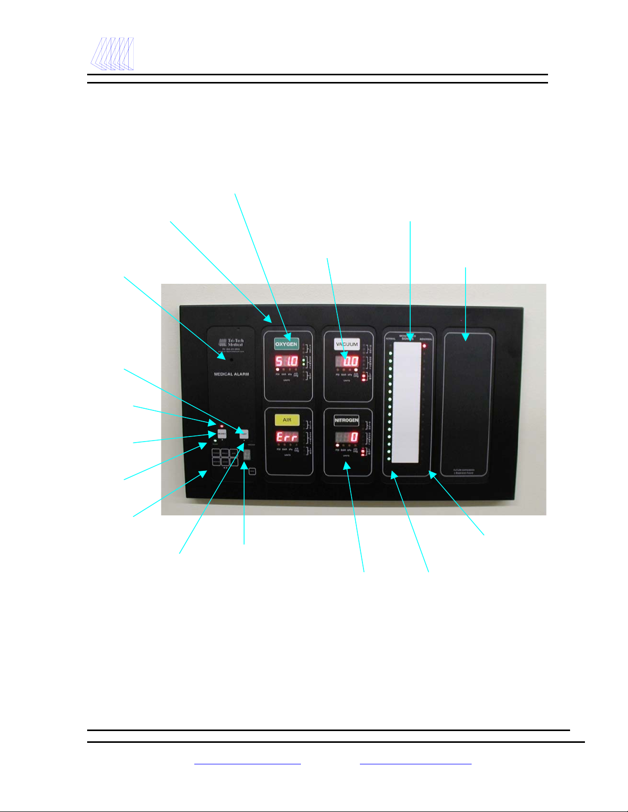
Gas (Area)Module
Audible alarm location
Color coded gas
identification label
Digital pressure
display
Units of measure indicator
PSI and Hg or Bar or kPa
Remote signal (master) description label
Power on indicator
Alarm silence indicator
Alarm silence button
Program mode indicator
Alarm test button
Status code display
Programming keypad
Remote signals normal
status LEDs - Green
Slot for future expansion with label
Remote signals abnormal
status LEDs - Red

- 5 -
Tri-Tech
Medical Inc. Introduction
Introduction
The Tri-Tech Medical gas alarm system monitors the status of the medical gas distribution system and
provides audible and visual indicators. The alarm can be used in conjunction with the Tri-Tech Medical
MCP100A or ACP-100-A Interface Panel to communicate all alarm/status information to the building
management system. The Tri-Tech alarm system monitors the status of the medical gas sources in accordance
with NFPA 99 and CSA Z305.1, and are C.U.L. listed.
Features & Benefits
Microprocessor controlled
State of the art maintenance free electronics
provide excellent reliability.
Remote signal modules
Provides monitoring of 16 separate remote
devices.
Self test program – alarm code display
LED display reveals the nature of the malfunction
and reduces maintenance time.
Three year PC board guarantee
A quality product you can buy with confidence.
Independent multiple master alarms
When service is interrupted to one alarm the
other(s) continue to operate independently.
Transient signal filter
Prevents or reduces nuisance (false) alarms
signals created by RFI interference.
Transient alarm notification
Indicates which parameter experienced a transient
(brief intermittent) signal.
Audio & visual signal indicators
Audible alarm and visual display of both normal
and abnormal status of each signal monitored
assures prompt and informative indication of a
problem.
Programmable remote signals
Configure each remote signal independently
(either normally closed, normally open or turn
unused signals off).
Programmable gas module high and low set
points – (Programmed from factory at 60/40 psig
and 12 in Hg).
Compact unit
Requires minimal wall space.
Optional building management interface panel
Allows communication with building
management system.
Alarm history recall
Can recall previous alarm signals even after the
alarm condition has been corrected and the alarm
panel has been cleared.
CUL Listed
Alarm repeat feature
Adjustable from 5 minutes to 4 hours (factory
programmed for 10 minutes).
Easy to install and service
Hinged frame with lanyards for easy
accessibility.
.

- 6 -
Tri-Tech
Medical Inc. Introduction / Components
Rough-in box or back box
Transducer AssembliesFront panel or front

- 7 -
Tri-Tech
Medical Inc. Introduction / Components
Introduction
The Tri-Tech Medical gas alarm system monitors the status of the medical gas distribution system and
provides audible and visual indicators. The alarm panel can be interfaced with a Tri-Tech Medical MCP100-A
or ACP-100-A Building Management interface panel for remote monitoring of the entire facility.
The Tri-Tech Medical gas alarm system is a two or three section assembly comprised of a rough-in box, a front
panel and transducers (only if it is an area alarm or combination alarm).
Rough-in box
The rough-in box houses the power supply, fuse, on/off switch, and a terminal strip for electrical wiring. An
isolated transformer reduces the 110V or 220V AC input to low voltage DC.
Front panel
The front panel includes enclosed printed circuit boards with programming circuitry.
The CPU module includes a power on indicator, programming buttons, an audible alarm, and an LED
status display.
The Remote Signal module(s) can monitor up to 16 signals per circuit board. Multiple remote signal
modules can be ordered in a single alarm. The signals can be configured to display an abnormal
condition on either a normally closed (NC) or a normally open (NO) circuit. Each signal may also be
turned off if it is not being utilized.
The Gas (Area) module(s) on the front panel are identified with gas specific, color coded labels (per
NFPA 99 or CSA Z305.1). The gas displays include LED’s which indicate high/normal/low pipeline
pressure. A digital LED display shows the actual gas pressure. The gas pressure may be displayed in
PSI and Hg, or BAR or kPa. The unit is pre-programmed to display PSI / Hg from the factory, but
may be re-programmed in the field to display BAR or kPa.
Transducers
The transducer converts pressure to an electrical signal and supplies the electrical signal to the front panel.
After the initial 24 hour 150 psi standing pressure test (required per NFPA 99) has been completed the
pressure/vacuum transducers are mounted in the rough-in box. The transducers may be remotely attached to
the piping system at distances no further than 100 feet using Beldon 8777 shielded cable. Tri-Tech Medical
recommends mounting the transducers in the alarm back box – not remotely. Should a transducer require
service or replacement is considerably more time consuming to locate and replace or service remotely located
transducers

- 8 -
Tri-Tech
Medical Inc. Alarm Displays & Functions
Gas (Area)Module
Audible alarm location
Color coded gas
identification label
Digital pressure
display
Units of measure indicator
PSI and Hg or Bar or kPa
Remote signal (master) description label
Power on indicator
Alarm silence indicator
Alarm silence button
Program mode indicator
Alarm test button
Status code display
Programming keypad
Remote signals normal
status LEDs - Green
Slot for future expansion with label
Remote signals abnormal
status LEDs - Red

- 9 -
Tri-Tech
Medical Inc. Alarm Displays & Functions
Alarm Displays & Functions
CPU Module
Power on Indicator
The power on indicator (green LED) is illuminated
whenever electrical power (120 or 240 VAC) is
connected to the alarm.
Test Button
When the Test button on the front panel is pressed, the
alarm undergoes a self-test checking the lights and
displaying the gas settings. If errors are detected, they
are displayed on the status LED and/or on the area
module gas LED displays.
Status Display
The status LED displays system alert codes when a
problem occurs (these are numeric). See System Alert
Codes on page 34 for details.
The status LED also displays a “P” whenever the
alarm is in the program mode.
Alarm Silence
In the event of an alarm condition an audible alarm
sounds. The audible alarm can be silenced by pressing
the alarm silence button. Whenever there is an alarm
condition and the alarm has been silenced, the Alarm
Silence Indicator LED will be illuminated. The high
or low pressure LED or the remote signal LED will
remain illuminated until the alarm condition is
rectified.
Program Mode Indicator
The Program Mode Indicator LED is only illuminated
when the alarm has been placed in the program mode
(see Programming the Alarm page 25). It should be
noted that when this LED is illuminated and the alarm
is in the program mode, it is not monitoring or
reporting alarm conditions for the medical gas
systems.
History Button
The History button may be pressed and held at any
time to view alarm history. Viewing alarm history is
only active when the History button is depressed,
releasing the button returns the alarm to normal
operation. When depressed “H” will be displayed in
the Status Display LED.
Gas(Area) Module - If there was an alarm condition
for any gas (area) module, the High and/or Low
Pressure LEDs will be illuminated. If both the High
and Low Pressure LEDs are illuminated, the gas has
had both a High and Low alarm.
Remote Signal (Master) Module – If there was an
alarm condition for any Remote Signal the Red LED
will be illuminated. All other LED’s will be off.
Clear Alarm History – To clear alarm History you
simply press the History button, hold it down and
press Silence button (while the history button is still
depressed.
Program Button
See Programming the Alarm pages 25 – 27
Module Button
See Programming the Alarm pages 25 - 27
Units Button
See Programming the Alarm pages 25 - 27
Repeater Button
See Programming the Alarm pages 25 - 27
ID (Identification) Button
See Programming the Alarm pages 25 - 27
CPU Reset Button
See Programming the Alarm pages 25 - 27

- 10 -
Tri-Tech
Medical Inc. Alarm Displays & Functions
Gas Displays (Area Module)
Pressure Reading Display
The LED pressure reading displays the pressure as
indicated by the transducer. Whichever of the PSI or
BAR or kPa lights is illuminated reveals the unit of
measure displayed on the LED pressure reading. The
Nitrogen gas display indicates one tenth of the actual
pressure when displayed using kPa units (i.e. 1100 kPa
is displayed as 110 and the kPa x 10 LED is
illuminated).
High / Normal / Low Status Lights
In addition to digitally displaying the pressure of a
gas, the pressure is displayed by a series of green,
yellow & red LEDs reflecting the pressure as either
normal, high or low. These indications are relative to
the high and low pressure set points which have been
programmed into the alarm. These high and low set
points should be set in accordance with NFPA 99 and
CSA Z305.1 at ±20% of the normal operating
pressure.
As the pressure climbs above normal line pressure to
20% above normal line pressure, the LED’s on the
upper side of normal will illuminate, then the
uppermost normal & yellow High LED’s will
illuminate, finally the two red High LED’s will
illuminate. Simultaneously with the Red LED’s
illuminating, the audible alarm will sound.
As the pressure falls to below normal line pressure to
20% below normal line pressure, the LED’s on the
lower side of normal will illuminate, then the
lowermost normal & yellow low LED’s will
illuminate, finally the two red Low LED’s will
illuminate. Simultaneously with the Red LED’s
illuminating, the audible alarm will sound.
Units Button & PSI / BAR / Kpa LED’s
By placing the alarm in the program mode (see
Programming the Alarm page 25 ) the units button
toggles the LED pressure readings on the gas displays
between PSI (inches Hg for vacuum & evacuation
BAR / kPa LEDs. The corresponding PSI, BAR or
kPa LED is illuminate indicating which units are being
displayed on the gas display.
Note: Vacuum & evacuation are actually displayed as
inches Hg in the PSI mode. The Nitrogen gas display
indicates one tenth of the actual pressure when
displayed using kPa units (i.e. 1100 kPa is displayed
as 110 and the kPa x 10 LED is lit. The power on
LED is illuminated whenever electrical power is
connected to the alarm.
Note Alarm settings are maintained even if power is
interrupted.
Remote Signal Status LED’s
(Master Module)
Normal Status Light (Green)
The normal green status light when illuminated
signifies that the equipment being monitored is not in
an alarm condition. A flashing green light indicates a
normal condition, but a transient (see glossary of
terms for definition) signal from source equipment has
been detected.
Abnormal Status Light (Red)
The abnormal status light when illuminated signifies
that the equipment being monitored is in an alarm
condition.
Note: If no LED is illuminated the remote signal
status LEDs have probably been set in the unused or
off position. This can be verified by having the alarm
run a self-diagnostic check. Simply press the Test
button. As the alarm runs thru the test cycle, observe
the Status Display LED when the Remote Signal in
question is blinking. A “d” displayed on the Status
Display LED indicates that the Remote Signal has
been disabled.
Remote Signal Description Label
The remote signal description label identifies the
equipment that is being monitored on the normal and
abnormal LED’s to the left and right of the label.

- 12 -
Tri-Tech
Medical Inc. Operation
Gas (Area)Module
Audible alarm location
Color coded gas
identification label
Digital pressure
display
Units of measure indicator
PSI and Hg or Bar or kPa
Remote signal (master) description label
Power on indicator
Alarm silence indicator
Alarm silence button
Program mode indicator
Alarm test button
Status code display
Programming keypad
Remote signals normal
status LEDs - Green
Slot for future expansion with label
Remote signals abnormal
status LEDs - Red

- 13 -
Tri-Tech
Medical Inc. Alarm Operation
Alarm Operation
Refer to the Alarm Installation section for the procedure necessary to install the alarm. The Programming The
Alarm section covers the procedures to follow in order to configure the alarm if the preprogrammed settings
are not appropriate. After installation has been completed and the alarm has been properly configured, it is
ready for operation.
Remote Signal (Master) Module
With electrical power applied to the alarm, the
system will monitor the status of the medical gas
distribution system.
The remote signals (master) module displays (via
LED indicators) the normal/abnormal status of the
remote equipment connected to the alarm. In
normal operation all active signals will be green.
Whenever an abnormal status signal is detected the
corresponding green LED will be extinguished and
the red LED will light. Simultaneously an audible
alarm will sound. Pressing the Silence button
silences the audible alarm (the Red LED continues
to be lit). The appropriate personnel should be
notified immediately of the alarm condition.
When the alarm condition has been rectified the
Red LED is automatically extinguished and the
Green LED illuminates.
Whenever an intermittent Transient (see Glossary
of Terms for definition) abnormal status signal is
detected from remote equipment by the alarm, the
Green or Red LED will start to flash. Transient
alarms indicate a potential problem. The
appropriate personnel should be notified of the
alarm condition. Pressing the Test or Repeater
button returns the flashing LED to normal
operation.
Note The Remote Signal (Master) alarm is set to
Ignore transient signals that are less than 0.6
seconds in duration.
Pressing the Test button initiates a self-test of the
alarm. Each LED will illuminate in succession for
2.5 seconds. The displays are then cleared and the
system circuitry is checked for proper voltages. If
no errors are found, the alarm returns to normal
operation. If an error is found, the error is
indicated on the Status Code Display.
Gas Modules
With the electrical power applied to the alarm and
the gas systems adequately pressurized, the
following indicators are illuminated: 1) the Power
On LED, 2) the pressure readings of the gas on
each gas display, 3) the Normal LED (green) on
each gas display.
If the pressure of one of the gases drops below the
low limit setting, the following events take place
simultaneously: 1) the Normal LED will be
extinguished, 2) the Pressure Low LED (red) will
light up, 3) an audible alarm will sound.
If the pressure of one of the gases rises above the
high limit setting, the following events take place
simultaneously: 1) the Normal LED will be
extinguished, 2) the Pressure High LED (red) will
light up, 3) an audible alarm will sound.
Silencing the Alarm
Press the Silence button when the alarm is
sounding and the alarm will be silenced.
This alarm is equipped with a Repeater Delay
feature which monitors only the Gas Module
(Area) alarms. The Repeater Delay has been
factory programmed to make the alarm re-sound
every 11 (eleven) minutes as long as the alarm
condition exists. (Note: Remote Signal (Master)
alarms are not monitored by the Repeater Delay).

- 14 -
Tri-Tech
Medical Inc. Alarm Operation
Testing the Alarm
Pressing the Test button initiates a self-test of the
alarm, resets any system status alerts that may be
active and re-initiates the alarm-repeat function.
Pressing any key will abort the test displays but
not the internal tests.
The test commences in the following order:
1. The alarm will sound, the status display
will display “8” and the 1st active module
will be displayed with all lights
illuminated for 2.5 seconds. This is the
only time the alarm will sound and the
Program & Silence LED indicators will
illuminate during the test.
2. Each remaining active module will be
displayed with all lights illuminated for
2.5 seconds, in sequence. The Gas (Area)
Modules will be displayed first (if gas
modules exist). The Remote Signal
(Master) Modules will be displayed
second (if Remote Signal modules exist).
Each existing active module will be
displayed for 2.5 seconds.
3. After all existing modules have
completed the lamp verify test above, any
existing Gas (Area) Module set points
will be displayed for 2.5 seconds. If no
Gas Modules exist, these displays will be
bypassed. All the high set points will be
displayed for 2.5 seconds first with the
high alarm LEDs indicating which set
point you are observing. Any Master
modules that exist will not be illuminated
during this time. If a gas is not active, i.e.
the module exists but an “inactive shunt”
instead of a transducer is connected to the
gas, the gas display will be blanked.
4. Next the active Master modules will be
displayed, one at a time, displaying the
current alarm programming and the
contact state of each alarm point. Each of
the Master module displays will consist
of the following: The module will be
illuminated. The top parameter will be
flashing indicating it is the first alarm
point under test (the active alarm point).
The status display will display the current
contact state of the active alarm point.
This display will consist of: “C” =
closed, “O” = open, “d” = disabled. If
the active alarm point is disabled, both
alarm point LED’s (both the green & the
red) will be illuminated. This is only for
the test display. In normal operation,
both of the LED’s will be turned off.
After 2.5 seconds, the next lower alarm
point will flash and the status display will
show it’s contact state for 2.5 seconds.
This sequence will continue until the last
(bottom) alarm point has been displayed.
This action will continue until all active
Master module alarm points have been
displayed.
5. When all active modules have been
displayed (Gas and/or Master), the test
will be complete and the system will
return to normal operation. Remember,
you can exit the test at any time by
pressing any key.

- 15 -
Tri-Tech
Medical Inc. Alarm Installation
Alarm Installation
Installation of the Tri-Tech Medical alarm involves installing the rough-in box, the transducers (if it is an area
alarm or combination alarm) and front panel and making the necessary conduit, plumbing and electrical
connections. All installation and testing should be done in accordance with NFPA 99 or CSA Z305.1.
WARNING: All electrical power should be disconnected prior to installation.
WARNING: This device should only be installed by qualified personnel. Installation should not be attempted
by anyone not having general experience with the installation of devices of this nature.
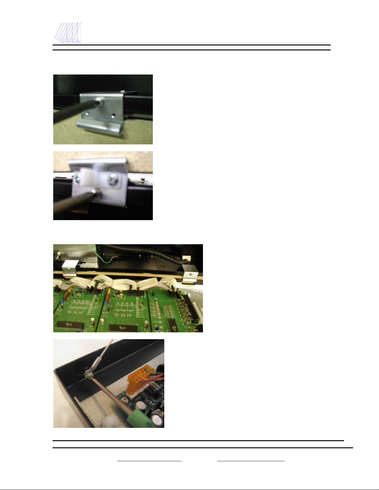
Rough-In Box Installation
(Side/end view of rough-in back box)
This is a rough-in box for a combination
alarm. Your rough-in box should look the
same or similar to this unit.
Refer to the building plans to determine the
location of the alarm.
The contractor is to provide rigid mounting
that will support the alarm box on both sides.
The metal flanges provided on both sides of
the rough-in box are to rest against the rigid
mounting brackets. Screws (contractor
provided) are to be driven thru the holes in
the metal flanges into the mounting brackets.
Mount alarm rough-in box so it will be flush
or just below the finished wall surface using
the adjustment feature on the flanges.

- 16 -
Tri-Tech
Medical Inc. Alarm Installation
Wiring
Route wires through the power supply conduit
installed in the bottom and left side of the rough-
in box. Connect the 110 or 220V AC facility
emergency power source electrical wiring to the
terminal strip provided on the lower left side of
the box. (N = neutral, H = hot, FG = field
ground)
The power supply hole is located in the bottom
(left side) of the rough-in box. Remove the
plaster cover and panel covering the power
supply. Remove the plug from the hole. Make
conduit connections for wiring from the facility
emergency power source.
To remove the power supply cover, loosen the
two screws at the top of the cover and slide the
cover to the right, then lift the cover over the
screw heads. Slide the wiring harness strain relief
to the left until it is free from the cover.
Use the ½” conduit knock-out provided on the
bottom left side of the rough-in box to route
conduit to supply either 110 or 220 V AC to the
power supply. Note: Separate conduit should
be used for low voltage wires (use knock outs
provided on the top of the box).
Neutral
Hot
Field
Ground

- 17 -
Tri-Tech
Medical Inc. Alarm Installation
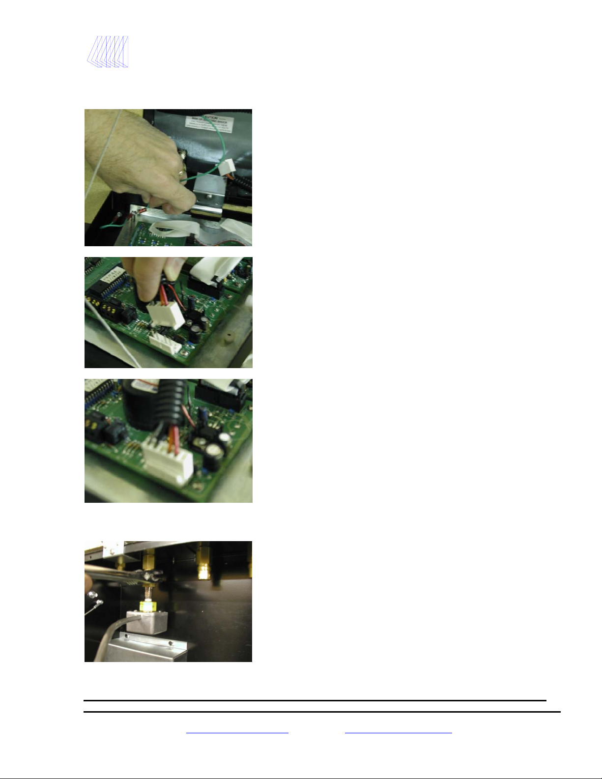
Plumbing the Riser Extension Tubes
The wiring harness will be provided pre-wired to
the power supply. If by chance it is not pre-
wired, the single green ground wire should be
fastened to the screw on the top left corner of the
power supply board. The wiring plug in
connector (which should contain the rest of the
wires), plugs into the connector terminal on the
upper left corner of the power supply board. The
black wire will be on the top.
This is how the power supply should look when
the wiring is completed.
Replace the power supply cover and plaster
cover (to protect the unit while the drywall and
wall covering work are being done) after wiring
is complete
Riser extension tubes
After removing the protective plastic caps, connect the
riser extension tubes (only included if this is an area or
combination alarm) to the gas piping system. Make sure
drop is for the proper gas service. Using a purge gas to
insure cleanliness in the tubes, silver braze the joints.
Do not use soft solder. Conduct heat away from the
check valves. (A purge kit is required for purge
equipment connection to the system). The 150 psi
standing pressure test of the piping system must be
successfully completed and all pressure removed from
the system before connecting the transducers to the
system. Attaching transducers without depleting the
150 psi standing pressure first will result in damage
to the transducers!
Note: It is recommended that gas piping system tubing be connected from the extension tube to the ceiling for
a future or blank gas display even though a transducer is not being installed. Cap the unused tube at the
ceiling. This will simplify future expansion.
Note: It is also possible to install the transducers remotely (not in the alarm box). In this type of installation
the riser extension tubes should be removed from the alarm back box and connected to gas piping system at a
distance not to exceed 100 feet (wiring harness length) from the alarm back box. Belden 8777shielded cable is
required.
Note: Tri-Tech Medical recommends mounting the transducers in the alarm back box – not remotely. Should
a transducer require service or replacement is considerably more time consuming to locate and replace or
service remotely located transducers.
- 18 -
Tri-Tech
Medical Inc. Alarm Installation
Installing the Hinges & Clips
Installing the Alarm Front Panel
After the walls are finished, the hinges and
clips may be installed onto the rough-in box.
The two hinges should be fastened to the lower
front edge of the rough-in box using the screws
provided. The hinge should rest flat against the
surface of the drywall.
The clips should be fastened to the upper front
edge of the rough-in box opposite the hinges
using the screws provided. The clip should rest
flat against the surface of the drywall.
Slide the holes cut into the bottom edge of the
front panel over the front catch of the hinges.
Support the front panel in the open position to
attach the lanyards.
Attach the two (left & right side) lanyard
cables to the alarm front panel using the
screws provided.
- 19 -
Tri-Tech
Medical Inc. Alarm Installation
Wiring the Alarm Front Panel to the Power Supply
Installing the Transducers
Attach the green ground wire, which
is in the wiring harness, to the
ground screw on the left corner of
the front panel – just in front of the
power supply.
Attach the plug connector at the end of
the wiring harness to the appropriate
connector located at the top left corner of
the CPU circuit board. The plug should
lock into place. The plug can only be
inserted one way.
This is how the wiring harness plug
connector should look when properly
installed on the back of the CPU board.
After depressurizing the 150 psi
standing pressure from the piping
system, install the appropriate
transducers to the appropriate riser
extension tube connectors inside the
rough-in box. Hand tighten then
torque lightly with a wrench.
- 20 -
Tri-Tech
Medical Inc. Alarm Installation
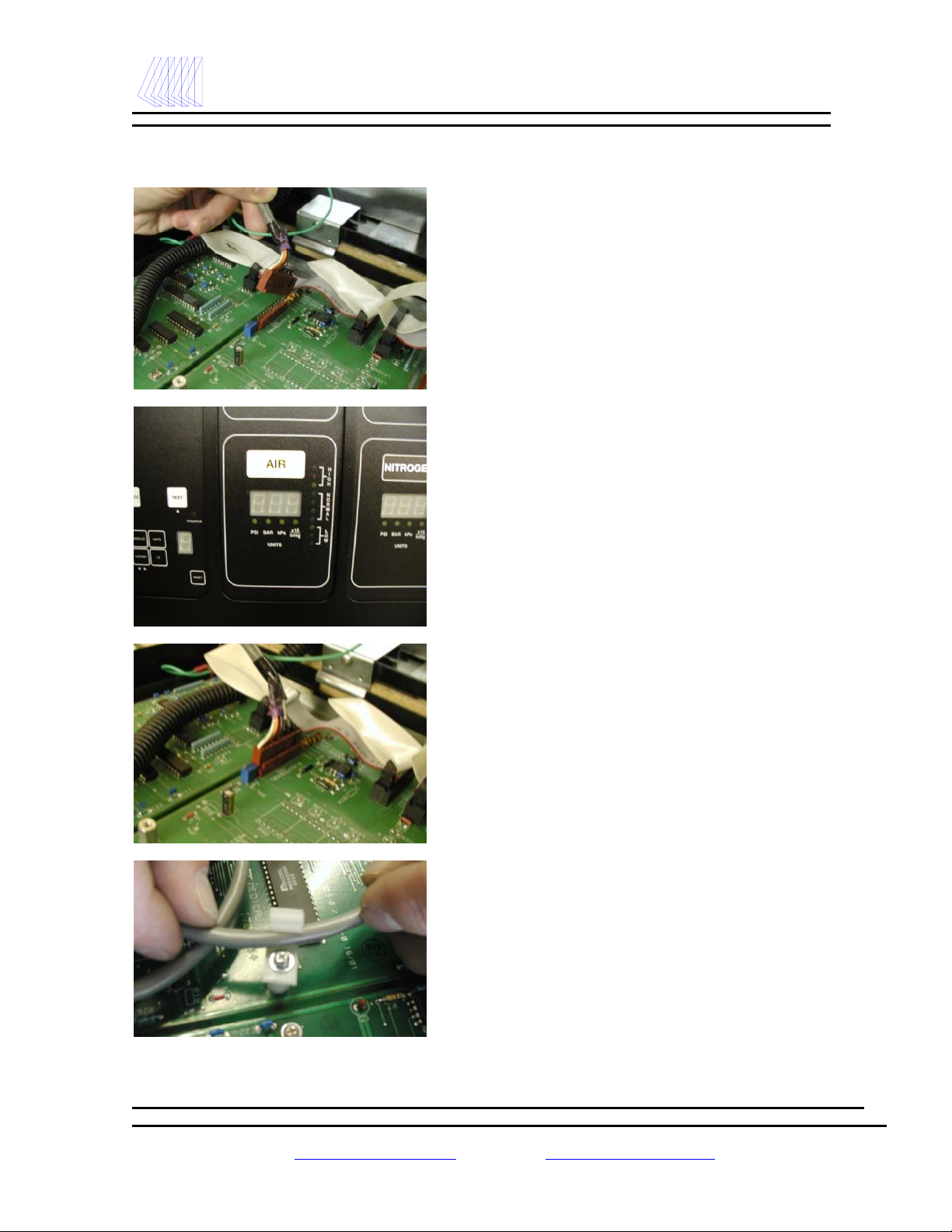
Connecting the Transducer Wiring to the Alarm Front Circuit Board
Insert the transducer cable underneath the cable clip
as shown using the clips provided.
Insert the plug(s) from the transducer(s) to
the appropriate connector(s) on the back of
the gas module circuit board(s). The plug on
the transducer and the panel connector are
both labeled by gas symbol at the factory for
proper installation. The plug can only be
inserted one way.
Visually verify that the appropriate
transducer plug is being attached to the
appropriate gas module by looking at the
front of the alarm panel.
The transducer plug will look like this when
it is connected properly to the gas module.
- 21 -
Tri-Tech
Medical Inc. Alarm Installation
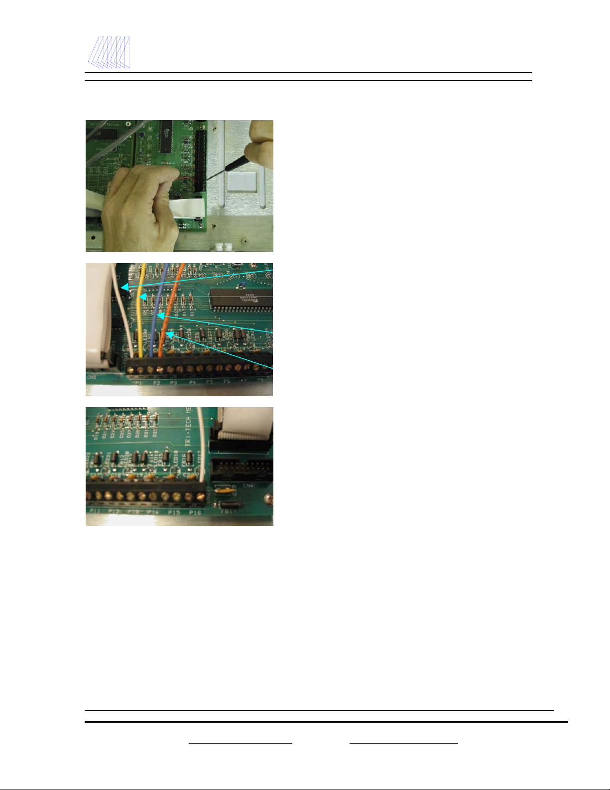
Wiring the Remote Devices to the Remote Signal (Master) Board
Locate the two banks of 16 terminal
connectors on the back of the
remote signal (master) board. There
are a total of 32 connection points –
two connection points for each
remote signal. The pairs are labeled
P1 thru P16 on the circuit board.
The top terminal of each pair is
where the signal wire should be
landed.
There are two options for landing the
common wire(s).
Option #1 – you can land the
corresponding common wire on the
bottom terminal of each pair of
terminal connectors.
This option is recommended for
maximum interference suppression.
Option #2 – you can connect all of
the common wires together and
land just one common wire on the
bottom terminal of P16.
Remote signal #1 –
signal wire
Remote signal #1 –
common wire
Remote signal #2 –
signal wire
Remote signal #2 –
common wire

- 22 -
Tri-Tech
Medical Inc. Alarm Installation
Labeling the Alarm Front
After all remote signal (master) wires have
been landed, identified & cataloged (using
appendix C in this manual), you are ready to
apply the remote signal labels. Remove by
unthreading the two nylon nuts shown here
from the back of the alarm front panel.
The panel will now lift out of the black frame.
Provided in the packaging with the alarm front
panel is a long white card and a pre-printed
sheet of labels for the remote alarm signals.
Wash your hands before handling these
labels and cards! Apply the labels to the
appropriate position on the card using the guide
lines on the card. When complete, insert the
card into the “Monitored Signals” label pocket -
between the stainless steel plate and the front of
the “Monitored Signals” label.
The gas modules are shipped pre-labeled from the
factory. If a gas service is changed to a different
gas or added to the alarm, it will be necessary to
insert the appropriate label in the pocket of the
gas module. The new gas label supplied by Tri-
Tech Medical will slide into the gas module label
pocket between the stainless steel plate and the
front of the gas module label.
When the labeling is completed, install the
stainless plate into the black frame and re-attach
with the two nylon nuts.
This manual suits for next models
1
Table of contents
Other TRI-TECH MEDICAL Medical Equipment manuals


Popular Medical Equipment manuals by other brands


AKW MediCare
AKW MediCare 3000 Series Installation and user care instructions

Super Star
Super Star S1100 Operation manual

Handicare
Handicare SystemRoMedic AmpSling Series manual

Ferno
Ferno Kwik Klip 031-4002 quick start guide

EDAN INSTRUMENTS
EDAN INSTRUMENTS SE-3 user manual

Current Solutions
Current Solutions ems 7500 instruction manual


