TRI-TECH MEDICAL TSD Series Manual
e6248r B 03/31/16 Tri-Tech Medical Inc., 35401 Avon Commerce Parkway Avon, Ohio 44011 No. 99-0278
Tel. 440-937-5691 Fax. 440-937-5060
Web site: https://tri-techmedical.com or Email: sales@tri-tech medical.com
Page 1of 6
Tri-Tech
Medical Inc.
Installation Operating Instructions for
Simple Duplex Manual Manifolds
TSD Series
s
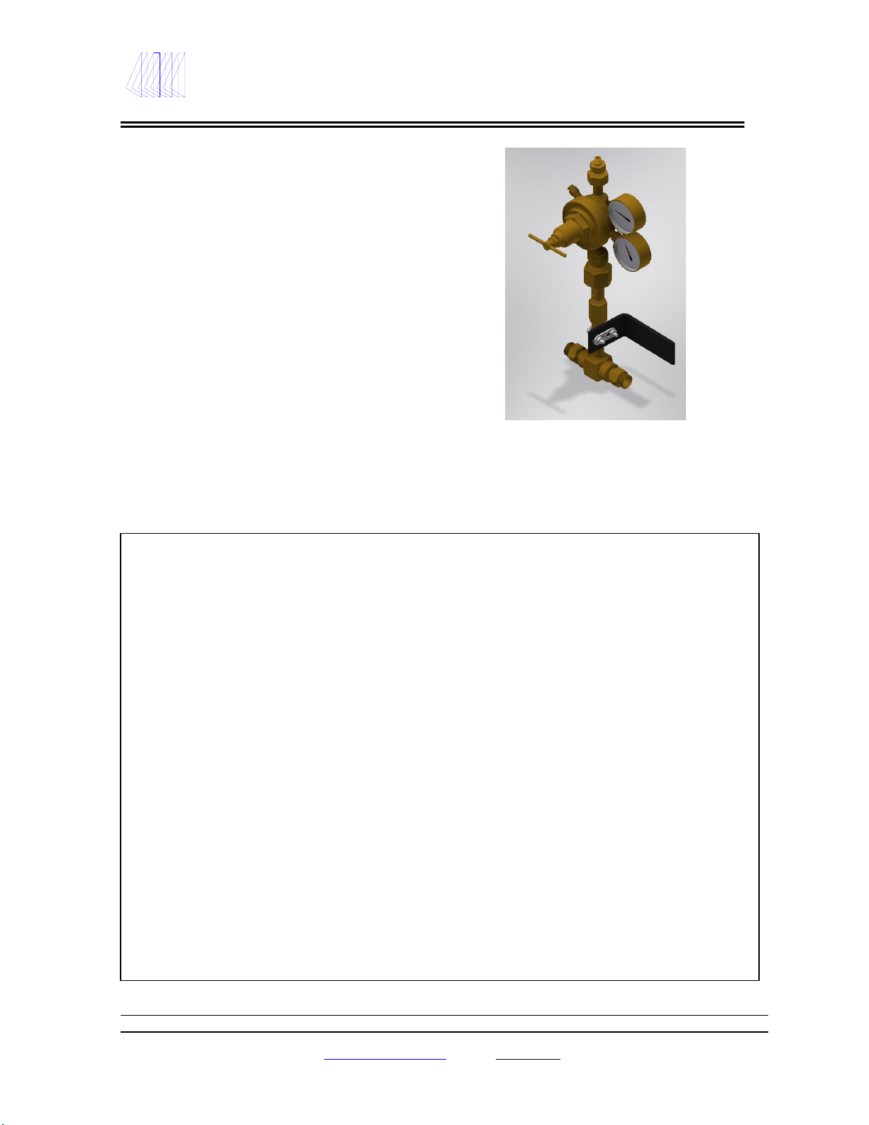
Model TSD shown above
Warranty: All Tri-Tech Medical manifolds are warranted against defects in materials and workmanship for
the period of five years from date of purchase.
Introduction
Tri-Tech Medical manifolds are cleaned, tested
and prepared for the indicated gas service and
are built in accordance with the Compressed
Gas Association guidelines. The manifold
consists of a regulator and a header, to provide
an increased supply of gas for the specific
application. Pressure gauges show system
status and alert the need to replace depleted
cylinders. Features of the manifold systems
include a regulator, flexible pigtails (copper
pigtails supplied with oxygen system –per
NFPA 99) with check valves and mounting
hardware.
Caution!
Failure to follow the following instructions can result in personal injury or property damage:
Never permit oil, grease, or other combustible materials to come in contact with cylinders,
manifold, and connections. Oil and grease may react with explosive force when ignited while in
contact with some gases –particularly Oxygen and Nitrous Oxide.
Cylinders, header and master valves should always be opened very S-L-O-W-L-Y. Heat of
recompression may ignite combustible materials creating an explosive force.
Pigtails should never be kinked, twisted or bent into a radius smaller then 3 inches. Mistreatment
may cause the pigtail to burst.
Do not apply heat. Oil and grease may react with explosive force when ignited while in contact
with some gases –particularly Oxygen and Nitrous Oxide.
Cylinders should always be secured with racks, chains, or straps. Unrestrained cylinders may fall
over and damage or break off the cylinder valve which may propel the cylinder from its current
position with great force.
Oxygen manifolds and cylinders should be grounded. Static discharges and lighting may ignite
materials in an oxygen atmosphere, creating an explosive force.
Welding should not be performed near Nitrous Oxide piping. Excessive heat may cause the gas to
dissociate, creating an explosive force.

e6248r B 03/31/16 Tri-Tech Medical Inc., 35401 Avon Commerce Parkway Avon, Ohio 44011 No. 99-0278
Tel. 440-937-5691 Fax. 440-937-5060
Web site: https://tri-techmedical.com or Email: sales@tri-tech medical.com
Page 2of 6
Tri-Tech
Medical Inc.
Installation Operating Instructions for
Simple Duplex Manual Manifolds
TSD Series
s
General Instructions
Manifolds should be installed in accordance with guidelines stated by the National Fire Protection Association,
the Compressed Gas Association, OSHA, Canadian Standards Association, and all applicable local codes. The
Carbon Dioxide and Nitrous Oxide manifolds should not be placed in a location where the temperature will
exceed 120°F (49°C) or fall below 20° F (-7°C). The manifolds for all other gases should not be placed in a
location where the temperature will exceed 120°F (49°C) or fall below -20°F (-29°C). A manifold placed in an
open location should be protected against weather conditions. During winter, protect the manifold from ice and
snow. In summer, shade the manifold and cylinders from continuous exposure to direct rays of the sun.
Leave all protective covers in place until their removal is required for installation. This precaution will keep
moisture and debris from the piping interior, avoiding operational problems.
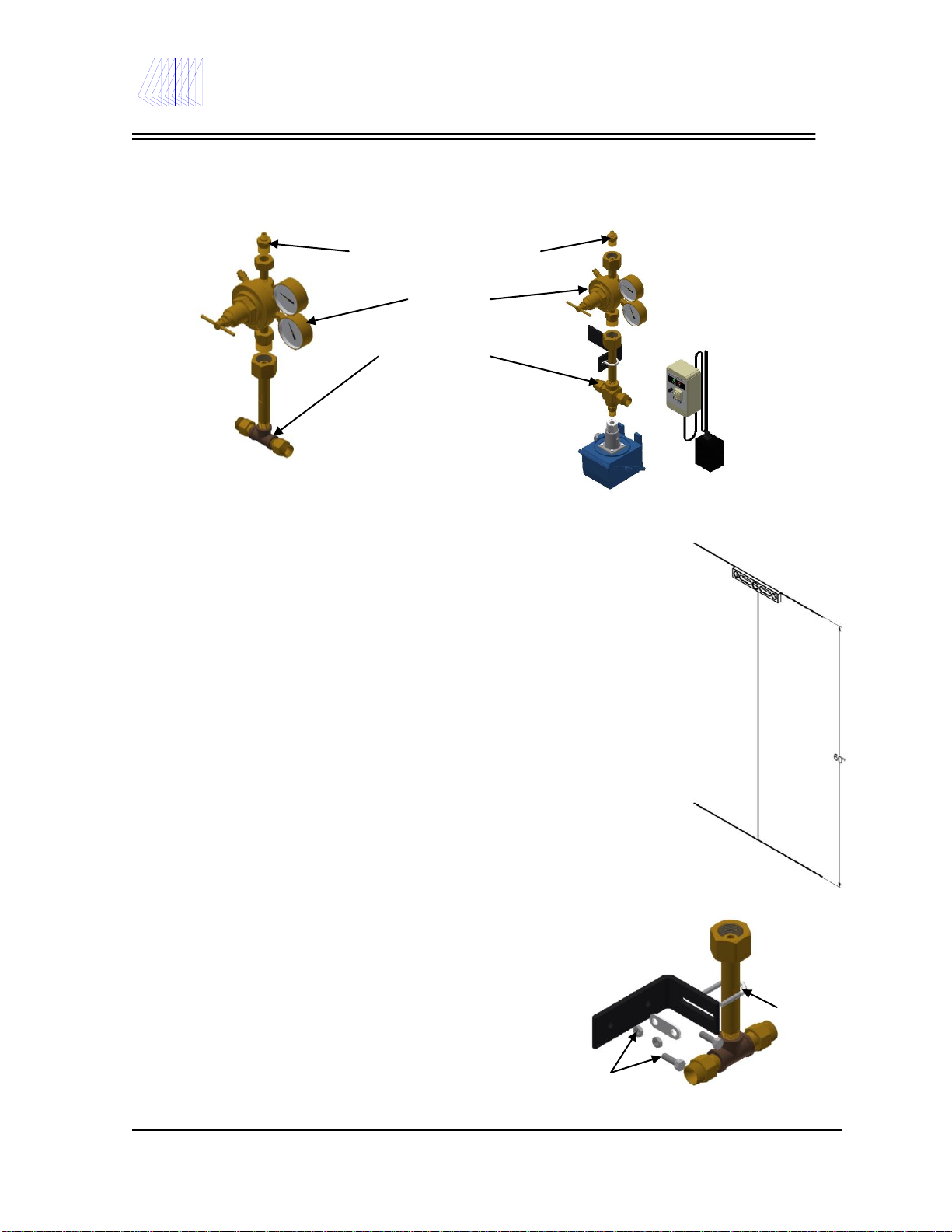
Wall Mount Floor Mount
FIGURE 1
Note: Mark the manifold on the wall from the center of the header bar to the floor is 60”
CAUTION:
Remove all protective caps prior to assembly. The protective cap may ignite due to heat of
recompression in an oxygen system.
e6248r B 03/31/16 Tri-Tech Medical Inc., 35401 Avon Commerce Parkway Avon, Ohio 44011 No. 99-0278
Tel. 440-937-5691 Fax. 440-937-5060
Web site: https://tri-techmedical.com or Email: sales@tri-tech medical.com
Page 3of 6
Tri-Tech
Medical Inc.
Installation Operating Instructions for
Simple Duplex Manual Manifolds
TSD Series
s
MANIFOLD ASSEMBLY
1. Assemble the manifold outlet fitting to the regulator outlet (Figure 2).
2. Assemble the headers assembly to the regulator inlet oriented as shown in Figure 2.
Manifold Outlet Connection
1/2" MNPT
Regulator
Header Section
Pressure Switch
FIGURE 2
Note: In some applications a relief valve may be required downstream of the manifold.
The relief valve is not included, it would be sold separately i.e. part no. RV-22-075 75 PSI,
RV-22-150 150PSI or RV-22-250 250PSI.
MANIFOLD INSTALLATION –Wall Mount Applications
1. Determine and mark the vertical center line for Spirit Level
installation of the manifold. (Figure 3).
2. Measure from the floor to a point 60” in height* of this vertical
line. Using a level, mark a horizontal line at this point extending
approximately 3” to the left and 3” to the right of center.
(*---Suggested manifold height. Wall mounting heights may Center
vary from one installation to another depending on available Line
space, cylinder height, etc.)
3. Remove the U-bolt assemblies from the mounting brackets.
Position the bracket so that the top of the bracket is aligned with
the horizontal line. Floor
Line
4. Mark the mounting holes and install fasteners suitable for the type
of wall construction. FIGURE 3
5. Mount the manifold by placing the header on the bracket. Fit the U-Bolt
over the header pipe and tighten the mounting nuts.
Header Assembly U-Bolt
Fasteners
Shown Right with:
optional cross, remote
alarm part # TAV-1 and
pressure switch part # PS-
160-3200.
Remote audio/visual
alarm –part # TAV-1

e6248r B 03/31/16 Tri-Tech Medical Inc., 35401 Avon Commerce Parkway Avon, Ohio 44011 No. 99-0278
Tel. 440-937-5691 Fax. 440-937-5060
Web site: https://tri-techmedical.com or Email: sales@tri-tech medical.com
Page 4of 6
Tri-Tech
Medical Inc.
Installation Operating Instructions for
Simple Duplex Manual Manifolds
TSD Series
s
MANIFOLD OPERATION
The TSD series manifolds are designed to operate in two ways; to provide an increased supply of gas as well as higher flow
rates than can be achieved using a single cylinder, or to provide a manual changeover to a reserve cylinder.
1. Install the two pigtails provided to the TSD manifold. Connect the two cylinders intended to be used.
Following the cylinder replacement guidelines on page 5.
2. S-L-O-W-L-Y open both cylinder valves (turn counter-clockwise to open). The high pressure gauge will show the
pressure of the cylinder having the highest pressure. (Figure 5)
3. Check the system connections for leaks using an oxygen compatible leak test solution. Correct any leaks
immediately.
4. Adjust the delivery pressure of the regulator to the desired pressure. The selection of the regulator set pressure may
vary due to application requirements. If a pressure setting less than 20 psig is required then a line regulator must
be installed at the manifold outlet.
5. Simulate a depleted bank by closing the cylinder valves and creating a flow of gas through the manifold. The
pressure reading on the gauges will drop.
6. S-L-O-W-L-Y open one of the cylinder valves (turn counter-clockwise to open). Note: this manifold is designed
so that one side is in service (cylinder valve open) while the second side is held in reserve (cylinder valve closed).
7. The manifold is now ready to supply your system.
Pressure Gauge
Regulator High Pressure Gauge
FIGURE 5
The manifold control includes the following components and features; regulator, flexible stainless steel braided pigtails
(or copper pigtails with oxygen systems) with check valve outlets. The manifold is designed to use a line regulator
(optional item) which can be mounted on the manifold outlet for delivery pressure less than 20 psig.
Gas flows through the manifold to the primary regulator and then through the line regulator (if installed). Final delivery
pressure is controlled by the either the line regulator or by the primary regulator should the application not require a line
regulator. (A line regulator is not provided with the manifold.)
As cylinders deplete the high pressure gauge on the regulator along with any alarm systems installed will indicate that the
bank of cylinders should be changed.
After replacing empty cylinder, the manifold is immediately ready for service.
Check Valve Outlets
oOuOutlets

e6248r B 03/31/16 Tri-Tech Medical Inc., 35401 Avon Commerce Parkway Avon, Ohio 44011 No. 99-0278
Tel. 440-937-5691 Fax. 440-937-5060
Web site: https://tri-techmedical.com or Email: sales@tri-tech medical.com
Page 5of 6
Tri-Tech
Medical Inc.
Installation Operating Instructions for
Simple Duplex Manual Manifolds
TSD Series
s
To insure proper operation, observe the following guidelines:
1. Carefully follow all instructions.
2. Be sure cylinder valve is fully opened.
3. Replace empty cylinder as soon as practical after the manifold has depleted, and the full reserve cylinder valve
has been opened, placing it in service.
CYLINDER REPLACEMENT AND HANDLING
1. Shut off cylinder valve on depleted cylinder.
2. S-L-O-W-L-Y loosen and remove the pigtail connection from the depleted cylinder.
3. Remove the depleted cylinder and replace the protective caps.
4. Remove the protective cylinder cap from the full replacement cylinder. With the valve outlet pointed away from
you or anyone else, slowly open each cylinder valve slightly, blow out any dirt or contaminants which may have
became lodged into the cylinder valve.
5. Place and secure full cylinders into position using chains, belts, or cylinder stands.
6. Connect pigtails to cylinder valves and tighten with wrench.
7. Open the header valve. S-L-O-W-L-Y turn the cylinder valve until each cylinder is fully on.
8. The manifold supply bank is now replenished and may be put in service by following the instructions on page 4.
(MANIFOLD OPERATION).
GENERAL MAINTENANCE
1. Main Section
a) Daily –record line pressure.
b) Monthly
1a. Check regulators and valves for external leakage.
1b. Check valves for closure ability.
c) Annually
1a. Check relief valve pressures.
1b. Check regulator seats.
2. Manifold Header
a) Daily –observe nitrous oxide and carbon dioxide systems for cylinder frosting or surface
condensation.
Should excessive condensation or frosting occur it may be necessary to increase manifold capacity.
b) Monthly
1a.Check cylinder pigtails for cleanliness, flexibility, wear, leakage, and thread damage. Replace
damage pigtails immediately.
3. Every 4 years
a) Replace all pigtails.
Table of contents
Other TRI-TECH MEDICAL Medical Equipment manuals


Popular Medical Equipment manuals by other brands


Getinge
Getinge Arjohuntleigh Nimbus 3 Professional Instructions for use

Mettler Electronics
Mettler Electronics Sonicator 730 Maintenance manual

Pressalit Care
Pressalit Care R1100 Mounting instruction

Denas MS
Denas MS DENAS-T operating manual

bort medical
bort medical ActiveColor quick guide

AccuVein
AccuVein AV400 user manual


