TRI-TECH MEDICAL SLP Series Assembly instructions

e6427rIR 03/17/17 Tri-Tech Medical Inc., 35401 Avon Commerce Pkwy., Avon, Ohio 44011 No. 99-0534
Tel. 1-800-253-8692 -or-440-937-6244 Fax. 440-937-5060
Web site www.tri-techmedical.com E mail address: sales@tri-techmedical.com
1
Tri-Tech
Medical Inc.
Manufacturer of
Medical Gas Piping Equipment
Installation, Operating & Maintenance Instructions
For
Tri-Tech Medical Sleep Lab Panel Series
SLP-2 Sleep Lab Panel
SLP-1 Sleep Lab Panel

e6427rIR 03/17/17 Tri-Tech Medical Inc., 35401 Avon Commerce Pkwy., Avon, Ohio 44011 No 99-0534
Tel. 1-800-253-8692 -or-440-937-6244 Fax. 440-937-5060
Web site www.tri-techmedical.com E mail address: sales@tri-techmedical.com
2
Tri-Tech
Medical Inc.
Sleep Lab Panels
Features & Benefits
Features & Benefits
•Five year parts and one year labor warranty
•Provides 50 psi (3.4 bar) – Oxygen Source
•Check Valve Risers – allow easy service
•Sleep Lab Panels meet or comply with NFPA 99 Standards
– simplifying connections and reducing cost
•Easy to service layout/design
•Flowmeter control panel incorporates dial adjustment
•Ease of maintenance
•DISS gas specific connections
•Single flowmeter panel
•Dual flowmeter panels

e6427rIR 03/17/17 Tri-Tech Medical Inc., 35401 Avon Commerce Pkwy., Avon, Ohio 44011 No 99-0534
Tel. 1-800-253-8692 -or-440-937-6244 Fax. 440-937-5060
Web site www.tri-techmedical.com E mail address: sales@tri-techmedical.com
3
Tri-Tech
Medical Inc.
Table of Contents
Contents
Features & Benefits---------------------- 2
Introduction ------------------------------- 4
Warranty ---------------------------------- 4
Installation--------------------------------- 5
Installation of Inlet and Outlet DISS--- 5
Sleep Lab Panel Installation-------------- 5
Maintenance ------------------------------- 6
Flowmeters --------------------------------- 7
Operating Instruction ---------------------- 7
Cleaning / Maintenance------------------ 7
Trouble Shooting Guide----------------- 8
Appendix A
Technical Specifications----------------- 10
Technical Assistance----
Phone 800-253-8692
or 440-937-6244
Fax 440-937-5060
E-mail sales@tri-techmedical.com

e6427rIR 03/17/17 Tri-Tech Medical Inc., 35401 Avon Commerce Pkwy., Avon, Ohio 44011 NO. 99-0534
Tel. 1-800-253-8692 -or-440-937-6244 Fax. 440-937-5060
Web site www.tri-techmedical.com E mail address: sales@tri-techmedical.com
4
Tri-Tech
Medical Inc.
Introduction for
Sleep Lab Panel
Introduction
Tri-Tech Medical Sleep Lab Panel components are cleaned for use with oxygen. Each inlet and outlet DISS assembly is
tested for leakage. Each unit is designed and built in accordance with the National Fire Protection Association and
Compressed Gas Association guidelines.
The installation and maintenance should be conducted in accordance with the following standards:
NFPA 99 or CSA Z7396.1
Warranty
Effective for shipments made 4/1/2015 and after, the Seller warrants the products described herein to be free from
defects in material and workmanship for sixty (60) months from date of shipment with the exception of any components
which are recommended to be replaced in less than sixty months in our Installation/Operation manuals. Within said
period Tri-Tech Medical Inc. will repair or replace any part or component which is proven to be defective in either
material or workmanship. Effective for shipments made 9/1/2015 & after, the seller warrants labor necessary to replace
defective component (s) in accordance with seller re-imbursement program. This warranty is valid only when the
product has been properly installed according to Tri-Tech Medical Inc. specifications, used in a normal manner and
serviced according to factory recommendations. This warranty does not cover failures due to damage which occurs in
shipment or failures which result from accidents, misuse, abuse, neglect, mishandling, alteration, misapplication or
damage due to acts of nature. Seller makes no warranty with respect to products manufactured by others and furnished
hereunder; provided however, Seller shall extend to Buyer any warranties which it receives from such vendors.

e6427rIR 03/17/17Tri-Tech Medical Inc., 35401 Avon Commerce Pkwy., Avon, Ohio 44011 No. 99-0534
Tel. 1-800-253-8692 -or-440-937-6244 Fax. 440-937-5060
Web site www.tri-techmedical.com E mail address: sales@tri-techmedical.com
5
Tri-Tech
Medical Inc.
Installation, Operating Instructions
for Sleep Lab Panel
Installation of Inlet and Outlet DISS Assemblies
Inlet and outlet DISS assemblies must be installed in accordance with NFPA99 or CSAZ7396.1. An internal nitrogen
purge must be used during the brazing operation. The purge gas should flow away from the DISS body. Brazing
alloys per appropriate standards must be used. Before brazing, wet rags must be wrapped around the tube extensions
next to the DISS body to prevent overheating and possible damage to the DISS O ring seals. Direct the flame away
from the DISS body. The DISS body temperature must not exceed 300 degrees F to prevent damaging the O ring
seals.
The system must be tested (per appropriate standards) to ensure that no cross-connections have been made.
The system must be tested (per appropriate standards) for leaks.
Note: Pressure in the system will increase or decrease with temperature rise or fall.
WARNING: Miss-connection of the gases could lead to serious or fatal injury to patients. Following
installation, DISS connections must be tested for cross-connection (per appropriate standards) to ensure
that the intended services are correctly connected to the appropriate service lines.
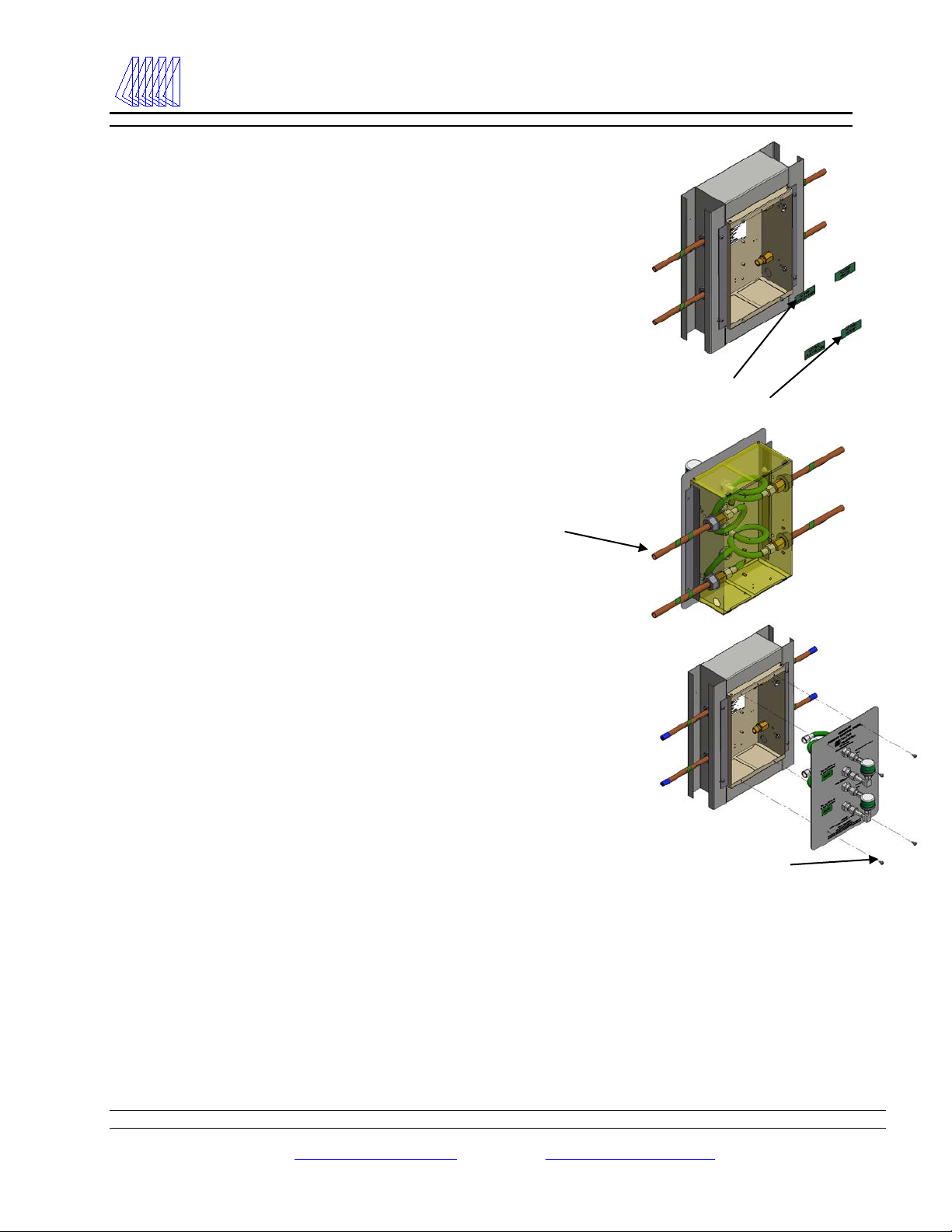
“X”
Adjustable
Flanges
Dust Cover
Plastic
Caps
Sleep Lab Panel Installation
1. Tri-Tech Medical Sleep Lab Panels may be plumbed in either direction –
with the patient (use) side on the left or the right. This saves the plumber
time and money.
2. The rough-in (back box) is shipped with a cardboard dust cover installed. You
will need to remove the dust cover to install the rough-in and perform the
pressure test. The dust cover should be re-installed after the pressure test to
protect the DISS connections until the wall covering (drywall, paint etc.) is
complete.
3. The DISS risers are shipped loose and must be installed in the back box.
4. Adjustable depth mounting flanges (top & bottom) should be utilized to align
front edge of box to be flush with the drywall surface.
5. The center of the rough-in box should be 60” in height above the finished floor.
Fasten the back box to horizontal braces installed between the studs so that the
front edge of the rough in box will be flush or slightly recessed with the finished
wall covering.
6. Before brazing, remove the plastic tube caps from the DISS assembly (risers)
copper extensions. DISS assemblies must be installed in accordance with
“Installation of Inlet and Outlet DISS Assemblies” above.
7. The system must be tested (per appropriate standards) to ensure that no cross-
connections have been made. The system must be tested (per appropriate
standards) for leaks. Note: Pressure in the system will increase or decrease with
temperature rise or fall.
e6427rIR 03/17/17Tri-Tech Medical Inc., 35401 Avon Commerce Pkwy., Avon, Ohio 44011 No. 99-0534
Tel. 1-800-253-8692 -or-440-937-6244 Fax. 440-937-5060
Web site www.tri-techmedical.com E mail address: sales@tri-techmedical.com
6
Tri-Tech
Medical Inc.
Installation, Operating Instructions
for Sleep Lab Panel
Inlet and
Outlet Labels
Mounting Screws
Sleep Lab Panel Installation
(Continued)
5. After the system passes the leak test, install the labels provided in the
back box paying careful attention to the direction of the gas flow (left to
right, or right to left). The direction of flow affects where you place Inlet
and Outlet Labels in the back box.
6. After the wall covering is complete, the dust cover may be removed
from the rough-in box and the hose assemblies and front panel may be
installed.
7. Make sure the hose assemblies are attached to the appropriate inlet/flow
meter connection point, and outlet/flow meter connection point. Failing
to do so may affect the patient and the sleep lab test results.
Note: Sleep Lab Panels me be plumbed in either direction – with the
patient (use) side on left or the right.
8. When all connections are complete and leak tested with an oxygen
compatible leak test solution, fasten the sleep lab front panel to the back
box with the four #8-32 x ¾” screws provided.
9. On the front panel, label each flowmeter in the space provided with the
sleep room it controls (label not provided). See Appendix A
WARNING: Mis-connection of the gases could lead to serious or fatal injury to
patients. Following installation, medical gas lines must be tested for cross-
connection (per appropriate standards) to ensure that the intended services are
correctly connected to the appropriate service lines.
WARNING: Make certain the labeling coincides with the gas service, and areas
controlled by the Sleep Lab Panel and that it is easily read.

e6427rIR 03/17/17Tri-Tech Medical Inc., 35401 Avon Commerce Pkwy., Avon, Ohio 44011 No. 99-0534
Tel. 1-800-253-8692 -or-440-937-6244 Fax. 440-937-5060
Web site www.tri-techmedical.com E mail address: sales@tri-techmedical.com
7
Tri-Tech
Medical Inc.
Maintenance Instructions
for Sleep Lab Panel
Maintenance
1. Clean the exterior of the stainless steel Sleep Lab Panel with a glass cleaner. Strong solvents will damage the
etched screened printing on the sleep lab panel.
2. Never use glass cleaner on the flowmeters.
3. If it is necessary to clean the flowmeters wipe them clean with a cloth dampened with water
4. Wipe dry with a clean dry cloth.

e6427rIR 03/17/17Tri-Tech Medical Inc., 35401 Avon Commerce Pkwy., Avon, Ohio 44011 No. 99-0534
Tel. 1-800-253-8692 -or-440-937-6244 Fax. 440-937-5060
Web site www.tri-techmedical.com E mail address: sales@tri-techmedical.com
8
Tri-Tech
Medical Inc.
Operation Maintenance Instructions
for Sleep Lab Panels
Flowmeters
Accuracy: ± 10% of the indicated flow.
Operating Temperature: 69°F (20.6°C) to 71F° (21.6° C)
Storage Temperature: -40°F (40°C) to 140°F (60° C)
Max Humidity: 95 %
Note: Storage / Transport outside the specified range may cause damage to the flow meter.
Specifications are subject to change without notice.
Operating Instructions
Note: Tri-Tech Medical, Inc. recommends the use of kink proof patient tubing.
1. Be sure Dial Flowmeter is in the “OFF” position.
2. Connect the Dial Flowmeter to a 50 psi (3.4 bar) Oxygen Source.
3. Set the flow by aligning the Indicating Pointer ▼ to the desired flow.
Note: The accuracy of flow will be adversely affected by any variation of inlet pressure, ambient
temperature or outlet resistance from rated values.
L
WARNING
•Read this user manual before installing or operating the Dial Flowmeter.
•There is NO FLOW between settings. The Indicating Pointer ▼must point to a specific number on the
dial to obtain flow.
Caution
ONLY use appropriate indexed fittings to connect the Dial Flowmeter to appropriate source. Use Oxygen
connections for oxygen flowmeters and use Air connections for Air flowmeters.
Cleaning / Maintenance
1. Disconnect all connections before cleaning.
2. Clean exterior surfaces of the Dial Flowmeter with a cloth dampened with water.
3. Wipe dry with a clean cloth.
4. Store the Dial Flowmeter in a clean area free from grease, oil and other sources of contamination.
Caution
•DO NOT immerse the Dial Flowmeter in any kind of liquid. This will cause damage to the Dial
Flowmeter and will void the warranty.
•This Dial Flowmeter is not field serviceable.

e6427rIR 03/17/17 Tri-Tech Medical Inc., 35401 Avon Commerce Pkwy., Avon, Ohio 44011 NO. 99-0534
Tel 800-253-8692 or 440-937-6244 Fax. 440-937-5060
Web-site www.tri-techmedical.com E-mail address: sales@tri-techmedical.com
9
Tri-Tech
Medical Inc.
Trouble Shooting Instructions
for Sleep Lab Panels
Trouble Shooting
If the Dial Flowmeter fails to function, consult the Trouble Shooting Guide below. If the problem cannot be solved, consult
your provider.
Problem
Probable Cause
Remedy
No Flow
° Flowmeter set in OFF position.
° Dial set between settings.
° Internal failure.
°Hoses are not properly connected
between the DISS inlet and
Flowmeter
° Turn to desired setting
° Move Dial to flow setting
° Return to Tri-Tech Medical, Inc.
°Remove Front Panels and check
connections
Dial will not turn / Hard to turn
°Dial seized
°Return to Tri-Tech Medical, Inc.
Will not shut off
°Flowmeter not in OFF position.
°Turn Dial to the OFF position.
L
WARNING
To prevent risk of burns, fire, or injury to person(s):
°ALWAYS confirm prescribed flow before administering to patient and monitor flow on a frequent basis.
°Always follow ANSI and CGA standards for Medical Gas Products and Flowmeters and Oxygen Handling.
°DO NOT use oils, greases, organic lubricants or any combustible materials on or near this Dial Flowmeter.
°DO NOT use near any type of flame or flammable/explosive substances, vapors or atmosphere.
°DO NOT smoke in an area where oxygen is being administered.
°This Dial Flowmeter contains magnetic, ferrous material that may affect the results of an MRI.
°NO FLOW is delivered when the Indicating Pointer ▼is pointing to OFF.
°Flow is available only at the listed increments. There is NO FLOW between increments.
L
CAUTION
°Only personnel instructed and trained in its use should operate this Dial Flowmeter.
°Be sure all connections are tight and leak free.
°Only use oxygen-safe leak detector to test for leaks.
°DO NOT autoclave.
°DO NOT gas sterilize with (EtO) Ethylene Oxide.
°DO NOT clean with aromatic hydrocarbons.
°DO NOT immerse Dial Flowmeter in any kind of liquid. This will void the warranty.
°DO NOT attempt to repair the Dial Flowmeter.
°Store the Dial Flowmeter in a clean area when not in use.
NOTE:
The medical oxygen outlet you are connecting to in the patient room must be labeled “Not For Use With A Flowmeter”.
Flow regulation is controlled by the Dial Flowmeter that is on the Sleep Lab Panel.

e6427rIR 03/17/17 Tri-Tech Medical Inc., 35401 Avon Commerce Pkwy, Avon, Ohio 44011 No. 99-0534
Tel 800-253-8692 or 440-937-6244 Fax. 440-937-5060
Web-site www.tri-techmedical.com E-mail address: sales@tri-techmedical.com
10
Tri-Tech
Medical Inc.
Sleep Lab Panel
Appendix A
Left to Right Right to Left
Note: Sleep Lab Panels me be plumbed in either direction – with the patient (use) side on left or the right.

e6427rIR 03/17/17 Tri-Tech Medical Inc., 35401 Avon Commerce Pkwy., Avon, Ohio 44011 No. 99-0534
Tel. 1-800-253-8692 -or-440-937-6244 Fax. 440-937-5060
Web site www.tri-techmedical.com E mail address: sales@tri-techmedical.com
Tri-Tech
Medical Inc.
Manufacturer of Medical
Gas Pipeline Equipment
Tri-Tech
Medical Inc.
This manual suits for next models
2
Table of contents
Other TRI-TECH MEDICAL Medical Equipment manuals


Popular Medical Equipment manuals by other brands


Zenith
Zenith Therm-X Series user manual

Baywater Healthcare
Baywater Healthcare Freedom 600 user guide

CMI Health
CMI Health PC-66H quick guide

Masimo
Masimo Rad-97 Service manual

Boscarol
Boscarol OB500 FA operating instructions

Shenzhen Roundwhale Technology Co., LTD.
Shenzhen Roundwhale Technology Co., LTD. R-C1 instruction manual

Syneron
Syneron Candela VelaShape III System user manual

Sonoscape
Sonoscape E3 Quick manual

Skytrofa
Skytrofa Auto-Injector Instructions for use

Flight Medical Innovations
Flight Medical Innovations FLIGHT 50 Operator's manual

Ferno
Ferno F2 quick start guide

Vapotherm
Vapotherm precision flow Instructions for use