TRI-TECH MEDICAL Genesys Series Manual
- 1 -
Tri-Tech
Medical Inc. Manufacturer of
Medical Gas Pipeline Equipment
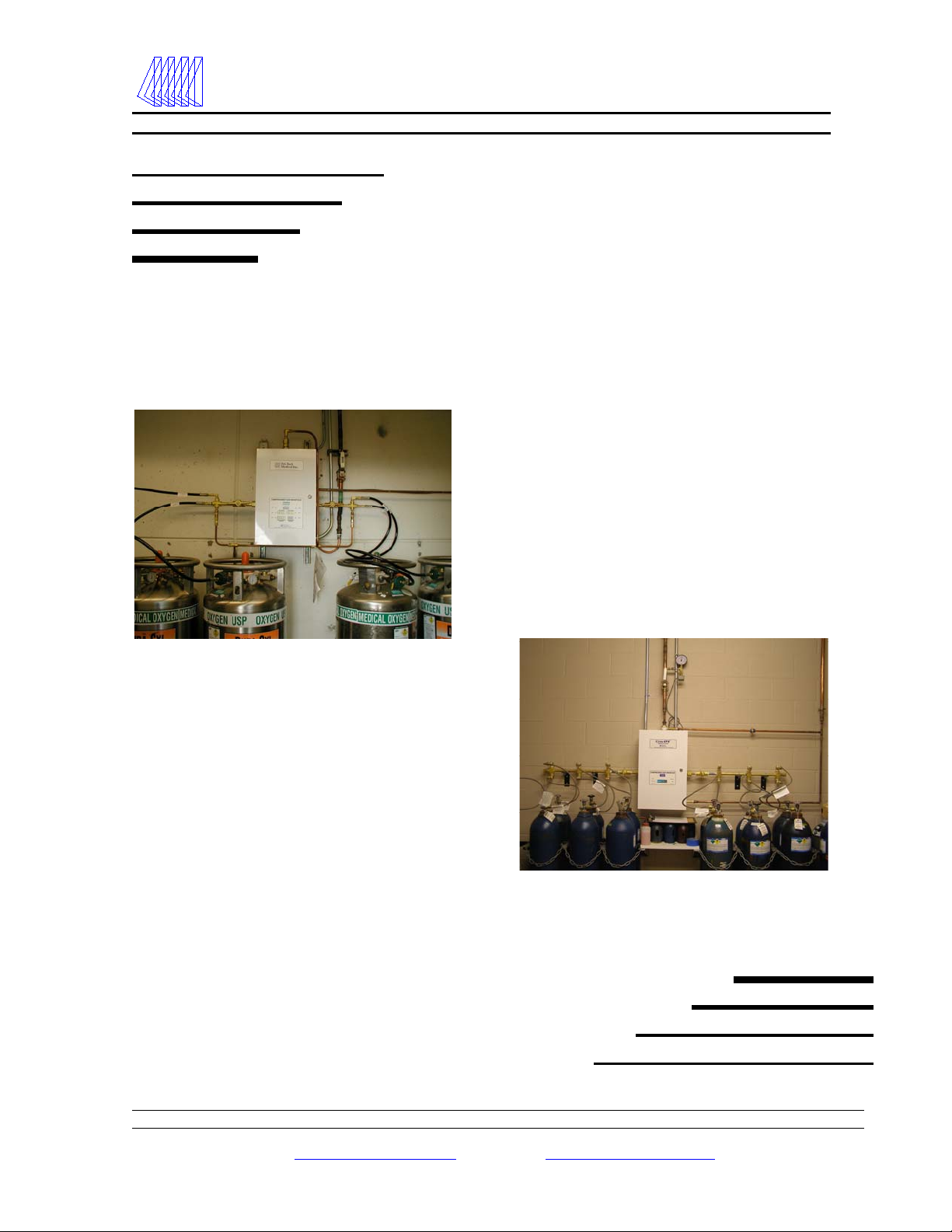
Installation & Operating Instructions for
Genesys ®
Series Manifolds
Model LLU
Model CCU

2
Tri-Tech
Medical Inc. Genesys®Manifold Systems
Features & Benefits
Features & Benefits
•Fully automatic changeover – no valves or levers to reset after each changeover
•Compatible with Tri-Tech Medical T-Net medical gas monitoring system saving you time and
improving safety
•Economizer software – ensures empty portable bulk vessels will not be put back into reserve
•Economizer hardware – allows head pressure from secondary portable bulk vessels to be used –
instead of vented
•Field upgradeable design – kits allow unit to be changed from - i.e. cylinders to portable bulk or
from standard flow to high flow or from lower delivery pressure to higher delivery pressure
•Circuit board triggers all required NFPA 99 alarms – simplifying wiring and reducing cost
•Unit includes hi/low line pressure transducer – eliminating need to purchase hi/low pressure switch
•Easy to service layout/design
•Microprocessor based control panel incorporates LED’s and illuminated text display readable even
in poor lighting conditions
•Electronic monitoring of circuits with 20 error, alarm or information messages displayed for ease of
maintenance
•Accurate, long life pressure transducers for monitoring of line pressure and bank pressures
•Analog gauges also provided for use in event of power failure
•Pressures may be displayed in PSIG / kPa / BAR
•Built in DISS gas specific emergency feed ports
•Built in emergency reserve bank ports
•Input power 120 VAC, 50 to 60 Hz
•Dual line pressure regulators on NFPA 99 models
•Gas specific header bar with integral check valves and cylinder pigtail assemblies
•Variety of header configurations available to meet the available space requirements of your
installation
•Available in weatherproof cabinet for outdoor installation

3
Tri-Tech
Medical Inc. Table of Contents
Contents
Features & Benefits ---------------------- 2
General Instructions --------------------- 4
Introduction-------------------------------- 4
Installation --------------------------------- 5
Mounting----------------------------------- 5
Plumbing ----------------------------------- 6
Electrical ----------------------------------- 8
Remote Alarm Wiring ------------------- 9
Installation – Pigtails & Cylinders ---- 10
Start Up and Checking Procedures --- 12
Model LLU Emergency Reserve
Plumbing & Wiring ---------------------- 14
Cylinder Replacement & Handling --- 15
Line Delivery Pressure Adjustment--- 15
Programming Adjustments------------- 16
General Maintenance -------------------- 17
Table of Error Codes -------------------- 17
Table of Alarm Codes-------------------- 18
Table of Information Codes ------------ 18
Replacement Parts------------------------ 19
Trouble Shooting Guide----------------- 21
Appendix A
Glossary of Terms ------------------------ 23
Appendix B
Technical Specifications ----------------- 24
Appendix C
Model CC Piping Schematic------------ 25
Appendix D
Model LL Piping Schematic ------------ 26
Appendix E
Operational Pressure Specifications -- 27
Appendix F
Relief Vent Plumbing -------------------- 28
Appendix G
T-Net Installation ------------------------- 29
Wiring Diagram – model CCU--------- 30
Wiring Diagram – model LLU --------- 31
Wiring Diagram – model CCU with heaters
------------------------------------------------ 32
Wiring Diagram – remote buzzer ----- 33

4
Tri-Tech
Medical Inc. Genesys®Manifold Systems
Introduction & General Instructions
Introduction
Tri-Tech Medical manifolds are cleaned for use with oxygen. Each system is tested for changeover, triggering of
alarms and leakage. Each unit is designed and prepared for the indicated gas service. Tri-Tech Medical manifolds are
built in accordance with the National Fire Protection Association and Compressed Gas Association guidelines.
Warranty
All Tri-Tech Medical manifolds are warranted against defects in material and workmanship for the period of one year
from date of purchase. All circuit boards are warranted against defects in material and workmanship for the period of
three years from date of purchase.
General Instructions/Location & Shelter
Manifolds should be installed in accordance with guidelines stated by the National Fire Protection Association, the
Compressed Gas Association, OSHA, and all applicable local codes. Carbon Dioxide and Nitrous Oxide manifolds
and cylinders should not be placed in a location where the temperature will exceed 120°F (49°C) or fall below 20°F
(-7°C). The manifolds for all other gas services should not be placed in a location where the temperature will exceed
120°F (49°C) or fall below 0°F (-18°C). A manifold placed in an open location should be protected against weather
conditions. During winter, protect the manifold from ice and snow. In summer, shade the manifold and cylinders
from continuous exposure to direct sunlight.
Leave all protective covers in place until their removal is required for installation. This precaution will keep moisture
and debris from the piping interior.
Caution
Failure to follow the following instructions can result in personal injury or property damage:
•Never permit oil, grease, or other combustible materials to come in contact with cylinders, manifold, and
connections. Oil and grease may react with explosive force when ignited while in contact with some gases
– particularly oxygen and nitrous oxide.
•Cylinder and master valves should always be opened very slowly. Heat of recompression may ignite
combustible materials creating an explosive force.
•Pigtails should never be kinked, twisted, or bent into a radius smaller than 3 inches. Mistreatment may
cause the pigtail to burst.
•Do not apply heat. Oil and grease may react with explosive force when ignited while in contact with some
gases – particularly oxygen and nitrous oxide.
•Cylinders should always be secured with racks, chains, or straps. Unrestrained cylinders may fall over and
damage or break off the cylinder valve which may propel the cylinder from its current position.
•Oxygen manifolds and cylinders should be grounded. Static discharges and lightning may ignite materials
in an oxygen atmosphere, creating a fire or explosive force.
•Welding should not be performed near nitrous oxide piping. Excessive heat may cause the gas to dissociate,
creating an explosive force.
•Remove all protective caps prior to assembly. The protective cap may ignite due to heat of recompression
in an oxygen system.
5
Tri-Tech
Medical Inc. Genesys®Manifold Systems
Installation Instructions
Control Cabinet Installation
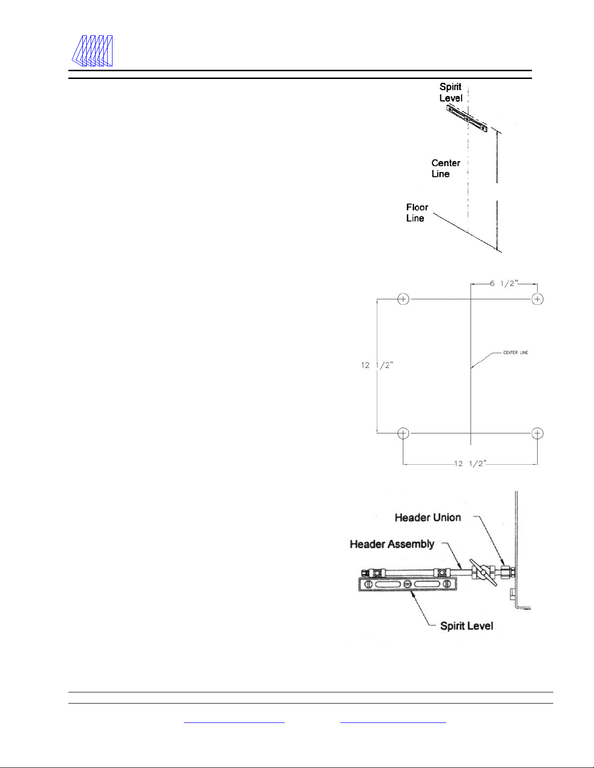
1. Determine and mark the vertical center line for
installation of the manifold control cabinet.
2. Measure from the floor to a point 60” in height*
above the finished floor of this vertical line. Using a
level, mark a horizontal line at this point extending
approximately 7” to the left and 7” to the right of
center. This line indicates the location for the bottom
two mounting bolts of the manifold control cabinet.
(* - suggested manifold height. Wall mounting
heights may vary depending on available space,
cylinder height, etc.)
3. Draw another horizontal line 12 ½” above and
parallel to the lower horizontal line. This line should
also extend 7” to the left and 7” to the right of center.
This line indicates the location for the upper two
mounting bolts of the manifold control cabinet.
4. Measuring from the vertical center line, along the two
horizontal lines, make a mark at 6 ¼” to the left and
another at 6 ¼” to the right of the vertical center line.
These four locations are the mounting hole locations
for the manifold control cabinet. Install the manifold
control cabinet using fasteners suitable for the type of
wall construction.
Header Installation
1. Attach the headers to the union on each side of the
manifold control cabinet. Using a level, mark the
placement of mounting brackets while keeping the
header on a horizontal plane.
2. Remove the U – bolt assemblies from the header
mounting brackets. Position the brackets so that the top
of the bracket is aligned with the bottom of the headers
and is centered between the cylinder connections. The
end bracket should be placed as close to the last cylinder
as possible to provide the most support and stability.
60”

6
Tri-Tech
Medical Inc. Genesys®Manifold Systems
Installation Instructions
1. Mark the mounting hole and install fasteners
suitable for type of wall construction.
2. Fit the U – bolt over the header piping and tighten
the two mounting nuts.
Plumbing – Model CCU
1. The outlet of the manifold is located at the top center
of the unit as shown here. The outlet connection is ½
NPT female. It is recommended that a ½ NPT male
union should be installed between the outlet of the
manifold cabinet and the pipeline system. This union
is available as an accessory from Tri-Tech Medical
(part # 17-0169).
2. A 6” x ½ npt brass pipe nipple has been provided (on
CC models) to extend the intermediate relief piping
outside the cabinet wall.
3. It is also recommended that unions (part # 17-0169)
be installed between all relief valves and the relief
(vent) pipeline system(s). There are two ½ NPT relief
valve connections on the model CCU manifold. See
Appendix F page 28.
4. The intermediate relief valve extension pipe nipple
must be installed. It is bagged and shipped inside of
the cabinet for protection during shipment.
Outlet ½ F npt Line relief valve ½ F npt
Intermediate relief connection
(6” x ½ npt brass nipple
shown)
17-0169 Union shown here
7
Tri-Tech
Medical Inc. Genesys®Manifold Systems
Installation Instructions
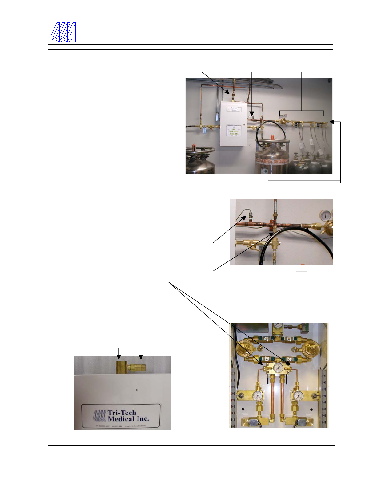
Plumbing – Model LLU
1. In addition to connecting the left & right
primary and secondary portable bulk
vessel supply banks, the LL models must
also have a high pressure reserve bank of
cylinders connected to the cabinet to be
in compliance with NFPA 99 guidelines.
2. The model LLU has one ½ NPT female
line pressure relief valve connection and
two 3/8 NPT female intermediate
pressure relief valve connections. (This
installation is typical – with the two
intermediate relief vent lines and the line
pressure relief vent line brought together
as a common vent line that exits the
facility either thru an exterior wall or the
roof). See Appendix F page 28.
3. A check valve (part number CV-050F)
must be installed between the emergency
reserve in use pressure transducer and
the high pressure reserve regulator.
4. The intermediate block has two ½ npt
plugs which may be removed to allow
the emergency reserve to be piped in
thru either the left or the right side of the
cabinet. Slots have been provided on
both the left and right sides of the control
cabinet to allow for the high pressure
reserve piping.
Emergency reserve low
pressure transducer (14-3001)
High pressure
reserve manifold
Emergency reserve in
use pressure transducer
Check valve (CV-050F)
Emergency reserve
in use pressure
transducer
(14-3002)
Intermediate
relief valve
Main line connection. Line pressure relief valve
(½ F npt outlet connection) (½ F npt outlet connection)
Main line outlet
connection
8
Tri-Tech
Medical Inc. Genesys®Manifold Systems
Installation Instructions
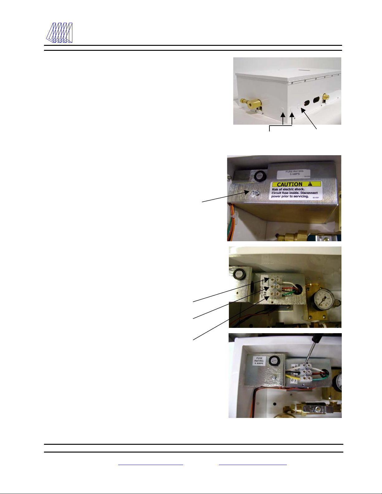
Electrical
1. Use one of the two ½” conduit knock-outs provided
located nearest to the top left corner of the cabinet
to route conduit to supply 120 VAC to the power
supply. Note: Separate conduit should be used
for low voltage wires (use knock outs provided
on the left side of the box).
2. Remove the power supply cover by loosening the
screw located at the top of the cover and then
sliding the power supply cover to the right until the
screw is in the center of the tear-drop shaped cut
out. Next, pull the cover forward until it clears the
screw head and the fuse. Note: the bottom of the
cover inserts into a slot in the back plate. Allow the
cover to rest on the dual line regulator assembly
plumbing just below the power supply.
3. Route wires of proper gauge (per local building
code requirement) through the power supply
conduit, thru the grommet on the power supply
bracket and into the terminal strip.
Neutral
Load
Field Ground
4. Connect the 120 VAC facility emergency power
source electrical wiring to the terminal strip
provided on the front of the power supply mounting
bracket (per photos right). (N = neutral, L = load,
FG = field ground)
Note: The ground must be a solid earth ground with
little or no resistance. A “noisy” earth ground may
affect the digital display of the manifold.
Conduit knockouts for
120 VAC
Conduit knockout for
low voltage alarm signals

9
Tri-Tech
Medical Inc. Genesys®Manifold Systems
Installation Instructions
Wiring – remote alarms
1. Wires for remote alarms should be brought into the
cabinet thru conduit or shielded cables (check local code
requirements) thru the knockouts on the left side of the
cabinet shown here. . Note: Separate conduit should
be used for high voltage wires – never run low
voltage wires in the same conduit as high voltage
wires.
2. If you are installing a model CCU (cylinder x cylinder)
cabinet there are three alarm signals recommended per
NFPA 99, High Line Pressure, Low Line Pressure and
Reserve in Use. The CCU circuit board will trigger all
three of these alarms (no hi/low pressure switch is
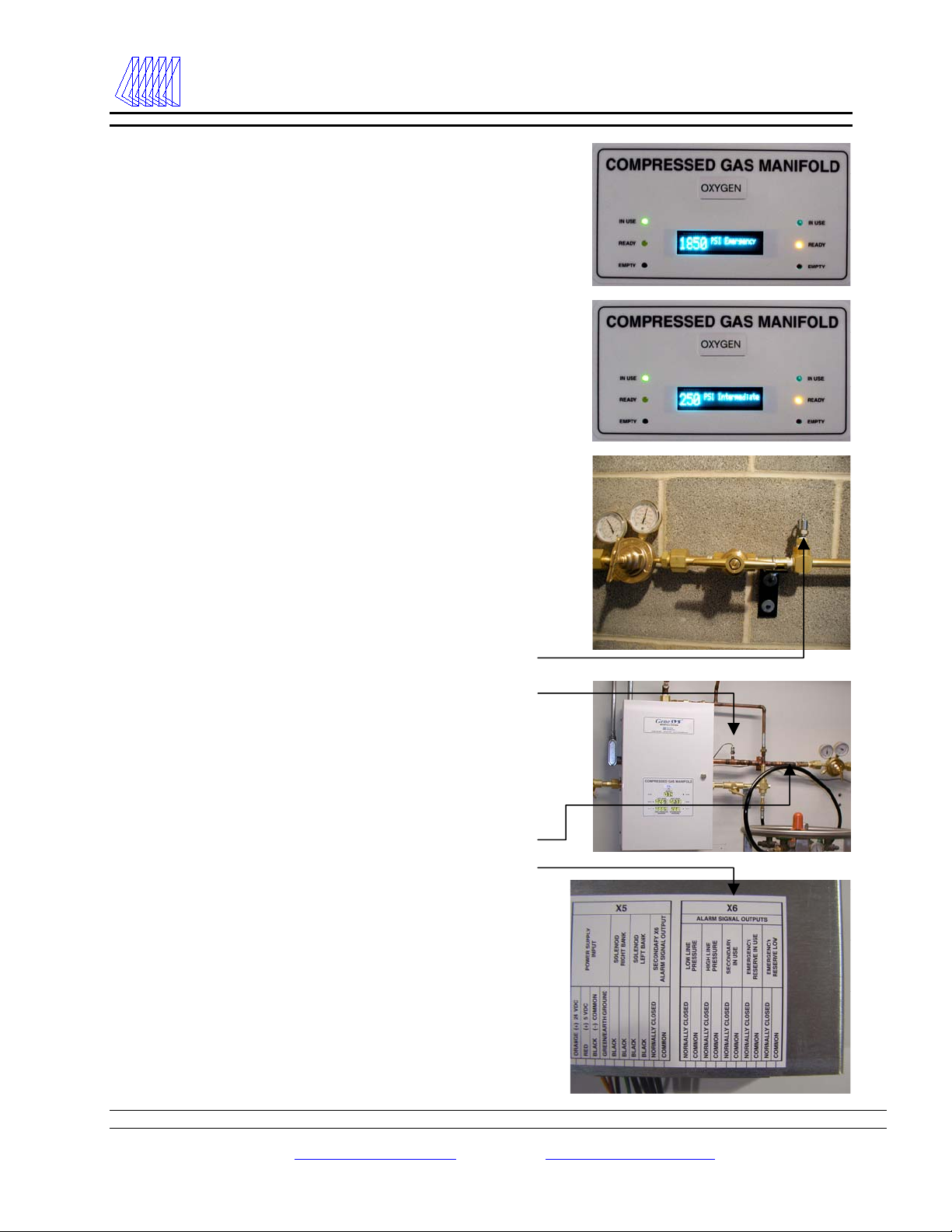
required). The line pressure transducer must be installed
outside of the cabinet – downstream of the source or
main line valve with the cable being wired to the
manifold circuit board to comply with NFPA 99. In this
photo the line pressure transducer has been assembled
into our PSM-XX assembly and connected to the gauge
port on the downstream (patient side) of the source valve
and wired to the manifold circuit board.
3. The line pressure transducer may also be mounted inside
the cabinet (as shown here). In this arrangement, a
hi/low pressure switch (sold separately) will be required
to meet the NFPA 99 recommendations. Note: the
hi/low pressure switch would be wired directly to the
master alarm panels – not to the manifold circuit board.
4. Remote alarm wires are connected to the circuit board at
the terminal gate labeled X6. Signal wires and Common
wires for Low Line Pressure, High Line Pressure and
Secondary in Use should be connected to the terminals
as indicated.
5. Note: all remote alarm terminals are normally closed
when the gas pressure is in the normal range. The
hi/low set points pre-programmed into the manifold
circuit board logic chip are as per the charts on page 27.
6. Note: an additional set of dry contacts labeled
“Secondary Alarm Signal Output” has been provided on
the X5 terminal to provide an alarm condition should the
120 VAC become disconnected.
Knock out for low voltage
remote alarm wiring
Line pressure transducer

10
Tri-Tech
Medical Inc. Genesys®Manifold Systems
Installation Instructions
Installing pigtails & attaching
cylinders – CCU models
1. The check valve outlet fittings on
the manifold header bars are CGA
(Compressed Gas Association) gas
specific threads. Each of these
fittings has an integral check valve.
Make sure the 3 digit CGA number
stamped on the outer perimeter of
these fittings matches the CGA
number stamped on the mating
CGA fittings on the pigtails.
2. Connect the pigtails to the check
valve outlets on the manifold
headers.
3. Check the master valves to be
certain they are open (turn counter-
clockwise to open). (Note: the
master valve should always be left
open. It is to be used only in the
event of an emergency).
4. SLOWLY open all cylinder valves
(turn counter-clockwise to open).
Check all cylinder and pigtail
connections for leaks using an
oxygen safe leak test solution (any
bubbles forming around
connections indicate leakage).
Check valve
outlet fittings
Line transducer
mounted on patient
side of source valve
using PSM-04 N2O
assembly.
Master valves
Attach pigtails to
header check valve
outlets using 1-1 /8”
open end wrench

11
Tri-Tech
Medical Inc. Genesys®Manifold Systems
Installation Instructions
Installing pigtails & attaching
cylinders – LLU models
1. This photo shows a completed
installation. Note the copper tubing
and unions are installed and
furnished by the installer.
2. The check valve outlet fittings on
the manifold header bars are CGA
(Compressed Gas Association) gas
specific threads. Each of these
fittings has an integral check valve.
Make sure the 3 digit CGA number
stamped on the outer perimeter of
these fittings matches the CGA
number stamped on the mating
CGA fittings on the pigtails. Attach
the pigtails to the check valve outlet
fittings on the manifold header bars.
3. Connect the other end of the pigtail
to the “Use” valve mating fitting on
the portable bulk vessel. Open the
use valve (turn counter-clockwise to
open). The pressure building valve
or regulator should be turned on or
opened for all vessels connected to
the manifold (both service and
reserve banks). Allow
approximately 1 hour for the
portable bulk vessel(s) to build
pressure.
4. Check all cylinder and pigtail
connections for leaks using an
oxygen safe leak test solution (any
bubbles forming around
connections indicate leakage).
5. Verify that the pressure being
supplied to the manifold cabinet
exceeds the minimum inlet pressure
requirements per the table on page
27.
Intermediate relief
lines with unions for
left bank, right bank.
Final line vent line
with union. Line
relief is ½ F npt,
intermediate reliefs
are 3/8 F npt. See
page 28 vent
plumbing diagram.
Ports for 2 pigtails
Intermediate
pressure relief valve
x 3/8 F npt
Common vent line thru
roof or outside wall. (3/4
recommended)
Final line vent line with
union.
Emergency reserve inlet.
12
Tri-Tech
Medical Inc. Genesys®Manifold Systems
Start Up & Checking Procedures
Start up & checking procedures
The manifold is pre-programmed (per page 27) and tested
before it is shipped. You may, however, wish to modify
some of the programming (see page 16). The unit has
been designed to allow some programming to be simply
and safely altered in the field.
1. Start with all portable bulk vessels and cylinders
turned off and with zero pressure supplied to the
manifold cabinet. To conduct the initial start-up
testing of the manifold, it is simpler and faster if
the circuit board is switched from the standard
‘cycling view’ (this is the mode in which it is
shipped) to the ‘global view’. To do this, the
cover must be removed from the circuit board and
the top #1 dip switch must be switched from the
RUN mode to the PROGRAM mode.
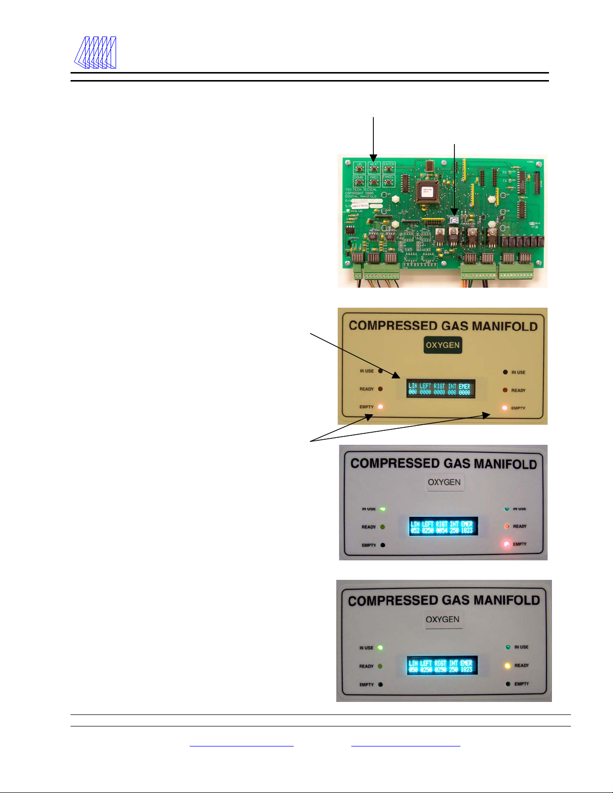
2. Turn on the 120 VAC to the unit. For model
CCU the display should illuminate showing all
zeros for the Line Pressure (LIN), Left Bank
Pressure (LEFT) and Right Bank Pressure
(RIGHT). The intermediate (INT) and
emergency reserve (EMER) displays should also
display zeros. The INT and EMER displays will
always display zeros on the global view screen of
CC models and will not display when the mode is
switched to the cycling view. (CC models). The
INT and EMER displays are only activated on LL
models. Both the left & right bank Red
(Depleted) LED’s should be illuminated. Both
the left and right bank Green (In Use) and Yellow
LED’s (Ready) should be extinguished.
3. SLOWLY open one cylinder valve on the left
bank. The left bank pressure gauge (inside the
cabinet) and the text display (on the outside of the
cabinet) should show the full pressure of the
cylinder. The Red (Depleted) LED for the left
bank should have extinguished leaving only the
Green (In Use) LED illuminated.
4. SLOWLY open one cylinder valve on the right
bank. The right bank pressure gauge (inside the
cabinet) and the digital display (on the outside of
the cabinet) should show the full pressure of the
cylinder. The Red (Depleted) LED for the right
bank should have been extinguished and the
Yellow (Ready) LED should have illuminated.
Program control buttons
Dip switch #1 RUN/PROGRAM
13
Tri-Tech
Medical Inc. Genesys®Manifold Systems
Start Up & Checking Procedures
Start up & checking procedures (cont’d)
5. Turn off all open left bank cylinder valves. Create a slight flow
of gas in the delivery pipeline system. DISS demand valves
have been provided on the line regulators. Mating DISS
fittings may be used to create a flow of gas within the manifold
cabinet. The left bank pressure text display and pressure gauge
should fall and the control automatically switches over to the
right bank. Delivery pressure remains constant. The left bank
Red (Empty) LED will illuminate. The secondary supply in
use alarm should activate on the master alarm(s).
6. SLOWLY reopen the cylinders on the left bank. The left bank
pressure gauge and digital display should return to full
pressure. The left bank yellow (Ready) LED will illuminate
simultaneously the left bank red (Empty) will extinguish. All
remote secondary supply in use alarms will be canceled.
7. Repeat steps 5 & 6 to simulate an empty right bank.
8. If the unit is a model LL, it will also display pressures for the
intermediate area (INT) and the emergency reserve (EMER)
and trigger the master alarm signal for “Emergency Reserve in
Use” and “Emergency Reserve Low”. To properly adjust the
emergency reserve regulator the primary and secondary banks
must both be shut off and the cabinet pressure drained.
SLOWLY open one cylinder on the emergency reserve bank
and observe the EMER pressure display and check to make
sure it agrees with the gauge on the emergency reserve
regulator. Adjust the delivery pressure from the emergency
reserve regulator following the table on page 27 (if this is a 50
psig line pressure application this regulator should be set to 65
psig). When testing the Emergency Reserve in Use and
Emergency Reserve Low master alarms please note – there is
a 10 second delay designed into the manifold logic. The
Emergency Reserve in Use alarm will be triggered when the
INT pressure falls below 70 psig (50 psig line pressure
application) for more than 10 seconds. The Emergency
Reserve Low alarm will be triggered when the EMER pressure
falls below 1200 psig for more than 10 seconds. Test the
Emergency Reserve in Use alarm by first pressurizing both the
primary & secondary and the emergency reserve banks, close
the valves on both the primary & secondary bank vessels,
establish a gas flow thru the manifold. Approximately 10
seconds after the primary then secondary banks deplete to
empty, the Emergency Reserve in Use alarm should be
triggered.
9. After you are satisfied that the manifold is functioning properly
and that all master alarm signals are being triggered properly.
The manifold circuit board should be returned to the ‘cycling
view’ mode. This is achieved by moving the dip switch from
the PROGRAM to the RUN position.
Dip switch #1 RUN/PROGRAM
14
Tri-Tech
Medical Inc. Genesys®Manifold Systems
Emergency Reserve – Model LLU
Model LLU – Emergency Reserve
Plumbing & Wiring
1. The model LLU includes digital displays for the
emergency reserve bank pressure and the intermediate
area pressure. (Refer to appendix E – page 27)
Remote master alarms will be triggered by the model LLU
for the five required NFPA 99 alarms; high line pressure, low
line pressure, secondary in use, emergency reserve in use and
emergency reserve low.
Refer to the appendix D on page 26 for information on
setting the delivery (outlet) pressure of the emergency
reserve regulator and pre-programmed emergency reserve in
use and emergency reserve low alarm set points.
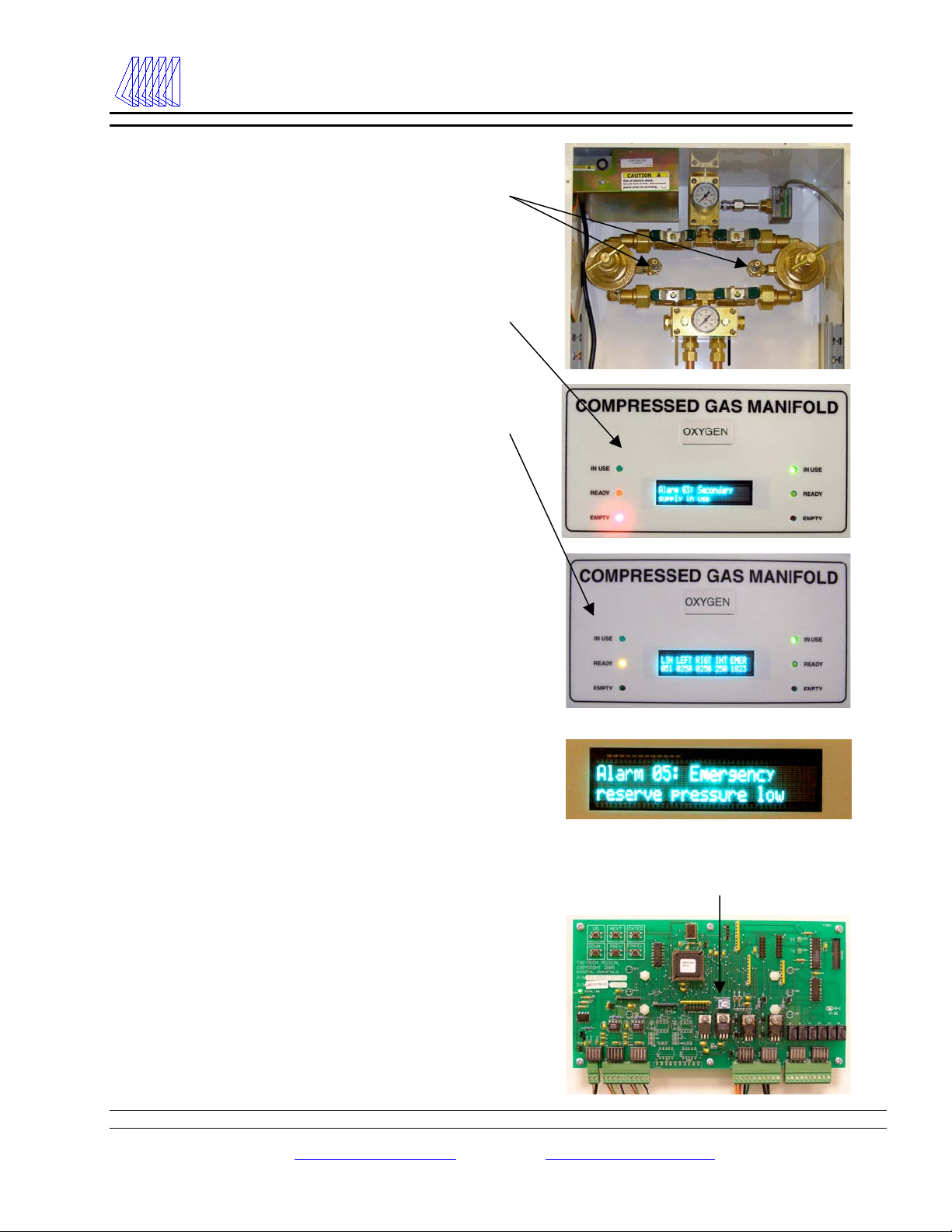
2. The emergency reserve low bank pressure transducer
(part # 14-3001) should be installed on the extra port on
the RWP series manifold. This port is located prior
(upstream) to the master valve and the regulator.
Note: if the 14-3001 and 14-3002 transducers are not
used (and pressure switches are used instead or not
used at all because a reserve manifold is not being
used) the “Reserve Alarms” programming option (see
page 16) must be disabled and the 35-3013 high
pressure reserve jumper kit must be installed or else
error codes will be displayed by the circuit board.
Emergency reserve low bank pressure transducer (14-3001)
Emergency reserve in use pressure transducer (14-3002)
3. The emergency reserve in use pressure transducer (part #
14-3002) should be installed on copper tubing (provided
by plumbing contractor) after (downstream) of the check
valve (part # CV-050F).
Check valve (part # CV-050F)
Master alarm signal wiring
(use X6 terminals on circuit board)
4. Both the emergency reserve bank pressure transducer
and the emergency reserve in use transducer must be
wired to the manifold circuit board as indicated by the
labeling instruction. Remote master alarm signal and
common wires must also be connected to the manifold
circuit board as indicated by the labeling instruction.
15
Tri-Tech
Medical Inc. Genesys®Manifold Systems
Cylinder Replacement & Line Pressure Adjustment
Cylinder replacement & handling
1. Close all cylinder valves on the depleted bank.
2. SLOWLY loosen and remove the pigtail
connection from the depleted cylinders.
3. Remove depleted cylinders and replace protective
caps.
4. Place and secure full cylinders into position using
chains, belts or cylinder stands.
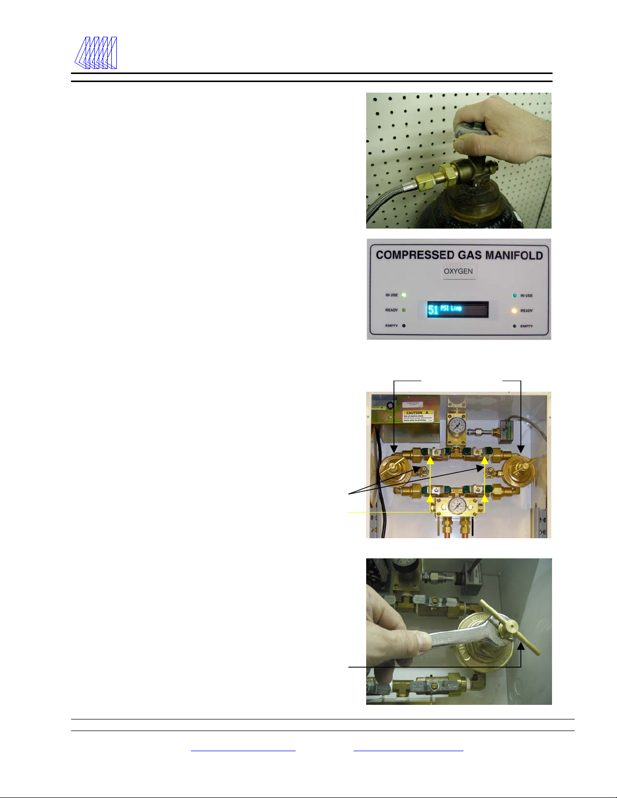
5. Remove protective cylinder caps from full
replacement cylinders. With the valve outlet
pointed away from all people in the area, slowly
open each cylinder valve slightly for a split
second to blow out any dirt or contaminants that
may have become lodged into the cylinder valve.
6. Connect pigtails to cylinder valves and tighten
with wrench.
7. SLOWLY turn each cylinder valve until each
cylinder is fully on.
8. Observe the following conditions: The red
(Empty) LED is extinguished and the yellow
(Ready) LED is illuminated and the secondary in
use alarm is cancelled.
9. The manifold supply bank is now replenished and
automatically placed in “reserve”.
Line delivery pressure adjustment
1. Leave the manifold in full operational status.
2. Create a flow condition in the delivery piping
system. DISS demand valves have been provided
on the line regulators for this purpose. Mating
DISS fittings may be used to create a flow of gas
within the manifold cabinet.
3. Open the manifold cabinet door and locate the
line pressure regulators. Ball valves on the inlet
and outlet sides of each regulator determine
which regulator is “on line” and which is “off
line”. Note: when the ball valve handle is
perpendicular to the pipeline, the ball valve is
closed. Per NFPA 99, one line regulator should
be valved closed and the other valved open.
4. Turn the T – bar handle clockwise to increase
pressure or counter-clockwise to decrease
pressure. It may be necessary to use a 3/4” open-
end wrench, loosen the locknut on the adjusting
screw (on high flow models only).
5. After adjustment, retighten the locknut on the
adjusting screw and close the cabinet door.
DISS demand valves
Ball valves
T – Bar Handle
Line regulators

16
Tri-Tech
Medical Inc. Genesys®Manifold Systems
Programming Adjustments
Programming Adjustments
The manifold is pre-programmed and tested before it is
shipped. You may, however, wish to modify some of the
programming. The unit has been designed to allow some
programming to be simply and safely altered in the field.
The aspects of the program which may be altered include:
the low line pressure alarm set point, the high line pressure
alarm set point, the emergency reserve low alarm set point
(LL models only), the reserve alarms (for both Emergency
Reserve in Use and Emergency Reserve Low) may be
disabled, the units of measure (psig, bar or kPa), the
calibration of the line pressure sensor, the display scroll
time (in seconds) and the logic software (this should only
be changed if the unit is being converted).
1. To make any programming change, the cover
must be removed from the circuit board and the
top #1 dip switch must be switched from the RUN
mode to the PROGRAM mode.
2. Once the #1 dip switch has been changed from
the RUN mode to the PROGRAM mode, the
display should look like this
3. Use the NEXT or PREVIOUS buttons to toggle
thru the menu choices. When you find the item
you wish to reprogram, use the UP or DOWN
buttons to display the new setting desired and
then use the ENTER button to save changes to the
programming. Note – if the ENTER button is
not pressed for each and every change, that
programming change will not be saved. The
display will display the word SAVED when you
have successfully saved a programming change.
4. Return the dip switch to the RUN position and
replace the circuit board cover when you are
finished making changes to the programming.
Displays showing common pre-programmed alarm set
points
Program control buttons
Dip switch #1 RUN/PROGRAM

17
Tri-Tech
Medical Inc. Genesys®Manifold Systems
General Maintenance & Error Codes
General Maintenance
Control Cabinet Headers & Pigtail
Daily Record line and bank pressures Observe nitrous oxide and carbon dioxide systems
for cylinder frosting or surface condensation. Should
excessive condensation or frosting occur it may be
necessary to increase manifold capacity.
Monthly Check regulators, compression fittings
and valves for external leakage.
Check valves for closure ability.
Alternate line regulator in use (if dual).
Inspect valves for proper closure.
Check pigtails for cleanliness, flexibility, wear,
leakage, kinked, pinched or twisted and thread
damage. Replace damaged pigtails immediately.
Inspect header check valve outlets for closure ability.
Annually Check relief valve pressures
Check regulator seats.
Every 4 years Replace all pigtails
Error Codes, Alarm Codes & Information Codes
Code
Displayed
Message Displayed Explanation
Error 01 Left bank sensor out of range This condition is activated when the left sensor’s raw readings are at
either extreme. Can be caused by a disconnected, wired incorrectly, bad,
or over-pressurized sensor.
Error 02 Right bank sensor out of range This condition is activated when the right sensor’s raw readings are at
either extreme. Can be caused by a disconnected, wired incorrectly, bad,
or over-pressurized sensor.
Error 03 Intermediate pressure out of range This condition is activated when the intermediate sensor’s raw readings
are at either extreme. Can be caused by a disconnected, wired incorrectly,
bad, or over-pressurized sensor. (LL models only).
Error 04 Emergency reserve out of range This condition is activated when the emergency sensor’s raw readings are
at either extreme. Can be caused by a disconnected, wired incorrectly,
bad, or over-pressurized sensor. (LL models only)
Error 05 Left bank pressure high In CC models this message is displayed whenever the left inlet bank
pressure exceeds 3,000 psi. In LL models this message is displayed
whenever the left inlet bank pressure exceeds 500 psi.
Error 06 Right bank pressure high In CC models this message would be displayed if the right inlet bank
pressure exceeds 3,000 psi. In LL models this message would be
displayed if either inlet bank pressure exceeds 500 psi.
Error 07 Intermediate pressure high Message is displayed whenever the intermediate pressure exceeds 500 psi.
(LL models only).
Error 08 Emergency reserve pressure high Message is displayed whenever the high pressure emergency reserve bank
pressure exceeds 3,000 psi. (LL models only).
Error 09 Line sensor noise detected Message is displayed if a gas board detects noise in the signal from it’s
digital sensor. Noise is detected if the protocol checksums do not match.
Error 10 Line sensor failed to respond Message is displayed if a line sensor is not responding.
Error 11 Line sensor is disconnected Message is displayed whenever a line sensor is disconnected.
Error 12 Secondary supply leak detected Message is displayed when a leak is detected in the secondary bank. (CC
models only).
Error 13 Emergency reserve leak detected Message is displayed when a leak is detected in the emergency reserve
bank. (LL models only).
Error 14 Gas type mismatch This error code is triggered by a mismatch in gas type between the line
sensor and user selected gas type in setup of the manifold circuit board.
18
Tri-Tech
Medical Inc. Genesys®Manifold Systems
Alarm & Information Codes
Error Codes, Alarm Codes & Information Codes (continued)
Code
Displayed
Message Displayed Explanation
Alarm 01 Line pressure low Message is displayed and low line pressure relay activated whenever the
line pressure is below the programmed low line pressure alarm set point.
Alarm 02 Line pressure high Message is displayed and high line relay activated whenever the line
pressure is above the programmed high line pressure alarm set point (high
line pressure alarm is triggered).
Alarm 03 Secondary supply in use Message is displayed and secondary in use relay activated when the
manifold has switched over to the secondary bank. Clears when tank is
replaced.
Alarm 04 Emergency reserve in use Message is displayed and emergency in use relay activated whenever the
intermediate pressure is below the programmed emergency in use
pressure alarm set point. (LL models only).
Alarm 05 Emergency reserve pressure low Message is displayed and emergency low relay activated whenever the
emergency pressure is below the programmed emergency reserve low
pressure alarm set point. (LL models only).
Info 01 Economizer in use – see manual Message is displayed whenever the ready bank pressure exceeds the
service bank pressure by 50 psig or more. The logic compares the service
and ready bank pressures once a second. (LL models only).
XX% Remains (CC models only - except for N2O & CO2 services). It calculates the
percent of gas remaining in the service bank.
Definitions and clarifications
Alarm Code – Alarm conditions per NFPA 99C and Z7396.1 guidelines.
Error Code – Messages that provide diagnostic information to assist in resolving system problems.
Information Codes – Messages that provide information regarding the operation of the system.

19
Tri-Tech
Medical Inc. Genesys®Manifold Systems
Replacement Parts
Item Part Number Description
Primary Regulator &
Repair Kit 68-0003 Primary regulator
68-0003RK Primary regulator repair/rebuild kit
Line Regulators &
Repair Kits 68-0004 Line regulator standard flow 5 - 125 psig
68-0004RK Standard flow line regulator repair/rebuild kit
68-0002 Line regulator high flow 5 - 125 psig
68-0002RK High flow line regulator repair/rebuild kit 5 - 125 psig
68-0001 Line regulator high flow 10-200 psig
68-0001RK High flow line regulator repair/rebuild kit 10 - 250 psig
Circuit Board 35-1001 LL series PLC board with digital displays
35-1002 CC series PLC board with digital displays
35-1003 CC series PLC board with text display
35-1004 LL series PLC board with text display
Power Supply AA400-C Power supply
Transducers/Sensors 14-3001 0 - 2,500 psig transducer with 12' cable ER Reserve Low
14-3002 0 - 500 psig transducer with 8' cable ER Reserve in Use
14-3003 0 - 250 psig transducer with 10' cable N2 for old style units
14-3004 0 - 100 psig transducer with 10' cable Oxygen for old style units
14-3005 0 - 100 psig transducer with 10' cable Med Air for old style units
14-3006 0 - 100 psig transducer with 10' cable N2O for old style units
14-3007 0 - 100 psig transducer with 10' cable CO2 for old style units
14-3024 0 - 250 psig transducer with 1.5' cable N2 for new style units
14-3025 0 - 100 psig transducer with 1.5' cable Oxygen for new style units
14-3026 0 - 100 psig transducer with 1.5' cable Med Air for new style units
14-3027 0 - 100 psig transducer with 1.5' cable N2O for new style units
14-3028 0 - 100 psig transducer with 1.5' cable CO2 for new style units
Solenoid Valves 48-1007 Solenoid valve for CC series
48-1008 Left Solenoid valve for LL series
48-1009 Right Solenoid valve for LL series
Check Valve 17-4003 Intermediate check valve 1/2 npt male x 1/2 OD tube
Tubes & Compression
Fittings 17-4012 Compression Sleeve 1/2 OD tube - glass filled Teflon
17-4005 Compression Nut for 17-4012
Q1100-1 1/2 OD copper tube x 7"
17-4013 Compression Sleeve 3/8 OD tube - glass filled Teflon
17-4024 Compression Nut for 17-4013
Gauges 14-1018 0 - 4,000 psig 1 1/2" x 1/8 m npt center back gauge
14-1016 0 - 400 psig 2" x 1/4 m npt bottom port gauge
14-1017 0 - 400 psig 1 1/2" x 1/8 m npt center back gauge
14-1009 0 - 300 psig 1 1/2" x 1/8 m npt center back gauge
14-1008 0 - 100 psig 1 1/2" x 1/8 m npt center back gauge
Relief Valves RV-22-075 75 psig x ½ M npt inlet with pipe away adaptor
RV-22-150 150 psig x ½ M npt inlet with pipe away adaptor
RV-22-250 250 psig x ½ M npt inlet with pipe away adaptor
RV-11-400 400 psig x ¼ M npt inlet with pipe away adaptor

20
Tri-Tech
Medical Inc. Genesys®Manifold Systems
Replacement Parts
Item Part Number Description
Pigtails for CC, TMC,
RWP & RSP Models
20-1001 24” single loop rigid copper O2 – CGA 540
20-0001 24” Flexible stainless braided O2 - CGA 540
20-0001CV 24” Flexible stainless braided O2 - CGA 540 w/ Check valve
20-1002 24” single loop rigid copper N2O – CGA 326
20-0002 24” Flexible stainless braided N2O - CGA 326
20-0002CV 24” Flexible stainless braided N2O - CGA 326 w/ Check valve
20-0003 24” Flexible stainless braided CO2 – CGA 320
20-0003CV 24” Flexible stainless braided CO2 - CGA 320 w/ Check valve
20-0004 24” Flexible stainless braided AIR – CGA 346
20-0004CV 24” Flexible stainless braided Air - CGA 346 w/ Check valve
20-0005 24” Flexible stainless braided Inert – CGA 580
20-0005CV 24” Flexible stainless braided Inert - CGA 580 w/ Check valve
Pigtails for LL & TML
Models
20-2001 72” Flexible – O2 – CGA 540
20-2002 72” Flexible – N2, Ar, He– CGA 580
20-2003 72” Flexible – CO2 – CGA 320
20-2004 72” Flexible – N2O – CGA 326
Union for Vent Lines 17-0169 Union 3 piece ½” M npt x ½” M npt 1 ¼ - 14 UNS
Master Valve GMV-1001 Master Valve 1/2" F npt x 1/2 F npt
Master Valve Repair
Kit
GMV-1001RK Master valve rebuild kit
35-3013 High Pressure Reserve Jumper Kit
Heater element 35-2001 Ceramic Heater
Accessory 35-3012 Manifold buzzer kit
This manual suits for next models
2
Table of contents
Other TRI-TECH MEDICAL Medical Equipment manuals


Popular Medical Equipment manuals by other brands


Getinge
Getinge Arjohuntleigh Nimbus 3 Professional Instructions for use

Mettler Electronics
Mettler Electronics Sonicator 730 Maintenance manual

Pressalit Care
Pressalit Care R1100 Mounting instruction

Denas MS
Denas MS DENAS-T operating manual

bort medical
bort medical ActiveColor quick guide

AccuVein
AccuVein AV400 user manual


