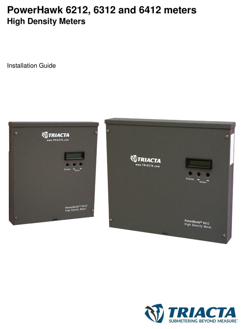
Triacta PowerHawk 6320 User manual

PowerHawk 6320
High Density Meter
Installation Guide

© 2013 Triacta Power Technologies All Rights Reserved
Triacta Power Technologies, and the Tricata logo are trademarks of Triacta
Power Technologies Inc.
All other trademarks that may be used in this document are the property of
their respective holders.
Copyright © Triacta Power Technologies Inc., 2004 to 2013
All rights reserved.
Triacta assumes no responsibility for the accuracy of the information
presented, which is subject to change without notice.
Disclaimers
This document contains confidential information which is proprietary to
Triacta Power Technologies Inc. Copying and/or distribution of this
material is prohibited without the prior approval of authorized Triacta
personnel.
Triacta products are intended for commercial uses. The customer hereby
agrees that the use, sale, licence or other distribution of the products for any
such application without the prior written consent of Triacta, shall be at the
customer's sole risk. The customer hereby agrees to defend and hold
Triacta harmless from any claims for loss, cost, damage, expense or
liability that may arise out of or in connection with the use, sale, licence or
other distribution of the products in such applications.
The warranties provided for Triacta products, if any, are set forth in
contractual documentation entered into by Triacta and its customers.
This document was originally written in English. If there is any conflict or
inconsistency between the English version and any other version of a
document, the English version shall prevail.

NOT FOR DISTRIBUTION WITHOUT THE CONSENT OF TRIACTA POWER
Triacta Power Technologies PowerHawk 6320
Table of Contents i
Table of Contents
PowerHawk 6320 Meter Installation Guide
System description.......................................................................... 1
PowerHawk 6320 system specifications .............................................................................. 1
Front panel display ......................................................................................................... 1
Installation
Pre-installation................................................................................. 4
Pre-installation check list ...................................................................................................... 4
Site planning ......................................................................................................................... 5
Access to power and lighting ......................................................................................... 5
Installation procedures ................................................................... 6
Mounting the PowerHawk .............................................................................................. 6
Installing voltage transformers for three-phase service greater than 120V ................... 6
Installing the reference voltage cable and power cable in a 120/240V application ........ 8
Using the auxiliary power input .................................................................................... 11
Installing the current transformers ............................................................................... 12
Using 5A CT converters with the PowerHawk 6320 meter .......................................... 15
Connecting the phone line ........................................................................................... 16
Connecting the Ethernet cable ..................................................................................... 16
Connecting pulse inputs ............................................................................................... 16
Start-up sequence for the PowerHawk 6320 meter ........................................................... 17
The initial report ........................................................................................................... 17
Display navigation .............................................................................................................. 18
Normal mode ............................................................................................................... 18
Diagnostics mode ........................................................................................................ 18
Recording the meter map ................................................................................................... 20
Regulatory Compliance
CSA .............................................................................................................................. 22
Federal Communications Commission (FCC) statement ............................................. 22
Industry Canada Class A emission compliance statement .......................................... 22
Avis de conformité aux normes d'Industrie Canada ..................................................... 23
Safety requirements and certification ................................................................................. 23
Access to equipment .................................................................................................... 23
Servicing the equipment .............................................................................................. 23
Equipment servicing ..................................................................................................... 23
Electrical safety compliance ............................................................................................... 23

NOT FOR DISTRIBUTION WITHOUT THE CONSENT OF TRIACTA POWER
Triacta Power Technologies PowerHawk 6320
ii Table of Contents

NOT FOR DISTRIBUTION WITHOUT THE CONSENT OF TRIACTA POWER
Triacta Power Technologies PowerHawk 6320
PowerHawk 6320 Meter Installation Guide 1
PowerHawk 6320 Meter Installation Guide
This document provides general information about the PowerHawk 6320 high-density meter,
and procedures to install and start up the unit, and complete the initial configuration.
• “System description” on page 1
• “Pre-installation” on page 4
• “Installation procedures” on page 6
• “Start-up sequence for the PowerHawk 6320 meter” on page 17
• “Regulatory Compliance” on page 22
Thisdocumentationisintendedfor thoseresponsible forinstallingandconfiguring PowerHawk
meters.
Installers must be licensed electricians with knowledge of local and national safety regulations.
System description
The PowerHawk 6320 high-density meter is single-phase, poly-phase, and three-phase devices
with 20 individual meters. All PowerHawk units are designed for residential, commercial and
industrial use with a wye service. They display the power and consumption readings for each
measurement point.
PowerHawk 6320 system specifications
The PowerHawk system architecture includes:
• single-phase, poly-phase (network) and three-phase compatiblity
• 120/240V and 120/208V configurations
• 20 individual meter points
• local Ethernet configuration interface via PC and web browser
• onboard modem and Ethernet ports for remote reporting
Front panel display
As shown in Figure 1, the PowerHawk 6320 has the following front panel features:
•LCD - displays 2 rows of 16 characters for each of the 20 meters
•Display button - cycles through the available information for each of the 20 meters
•Left and right arrow buttons - selects which of the 20 meters is on the display

NOT FOR DISTRIBUTION WITHOUT THE CONSENT OF TRIACTA POWER
Triacta Power Technologies PowerHawk 6320
2PowerHawk 6320 Meter Installation Guide
Figure 1: PowerHawk front panel

NOT FOR DISTRIBUTION WITHOUT THE CONSENT OF TRIACTA POWER
Triacta Power Technologies PowerHawk 6320
PowerHawk 6320 Meter Installation Guide 3
Table 1 lists the system specifications of the PowerHawk 6320 high-density meter.
Table 1: PowerHawk 6320 specifications
Specification Description
Dimensions Height: 16 in. (40.6 cm)
Width: 10 in. (20.3 cm)
Depth: 2 in. (5.1 cm)
Weight 5.5 lb (2.5 kg)
Reference input voltage 120/208V, 3W+N+PE
120/208V, 2W+N+PE
120/240V, 2W+N+PE
Voltage tolerance 108V to 127V
Maximum current 125 mA, 60 Hz
Current probes 200 A, 400 A, 800 A
Measurement accuracy Measurement Canada Approved
Pulse input Dry form A and solid-state form A compatible
Internal 3.3V pull-up
Maximum frequency 10 Hz
Minimum pulse width 20 ms
NVM storage 120 days in 15-minute intervals
Onboard modem V.90
Onboard Ethernet port 10 Mb/s
Fuse rating F1, F2, F3: T80 mA or T100 mA, 250V
F4: T80 mA or T125 mA, 250V
Operating temperature 32oF to 122oF (0 to 50oC)
Operating humidity 0 to 90% non-condensing
Usage environment For indoor use only
Maximum altitude 6562 ft. (2000 m)
Pollution degree 2
Installation Category II
Measurement Category III

NOT FOR DISTRIBUTION WITHOUT THE CONSENT OF TRIACTA POWER
Triacta Power Technologies PowerHawk 6320
4Installation
Installation
This section provides pre-installation, installation and system start-up procedures as follows:
• “Pre-installation” on page 4
• “Installation procedures” on page 6
• “Start-up sequence for the PowerHawk 6320 meter” on page 17
Pre-installation
This section provides information about activities that must be performed before installing the
equipment at the site. The following topics are covered:
• “Pre-installation check list” on page 4
• “Site planning” on page 5
Pre-installation check list
The following Triacta Power equipment is required for each installation:
• PowerHawk 6320 high-density meters
• two 25-pair CT cables per PowerHawk meter with amphenol connectors, available in
lengths of 13 ft. (4 m) or 26 ft. (8 m)
• serialized current transformers for metering
Note: The current transformers supplied by Triacta are certified, and comply with national
electrical codes.
When you receive your order, verify that the items listed above are included with the shipment,
and visually inspect them for damage. If any parts are missing or damaged, contact your Triacta
representative.

NOT FOR DISTRIBUTION WITHOUT THE CONSENT OF TRIACTA POWER
Triacta Power Technologies PowerHawk 6320
Installation 5
The installer must provide the following tools and equipment before proceeding with the
installation:
• an appropriate breaker for the type of panel: single-, poly-, or three-phase depending on
the installation, or a fused disconnect switch
• current/voltage meter to test the phasing of panels
• phone or butt set to test the phone line
• RJ11 junction box
• RJ11 splitter to tap into the existing junction box
• RJ11 patch cable
• xDSL filter if required (many businesses have their internet access on the same line as the
fax)
• RJ45 Ethernet patch cable
• 4-wire 14 AWG (1.63 mm2) cable for three-phase PowerHawk installation
• 3-wire 14 AWG (1.63 mm2) cable for single-phase or poly-phase PowerHawk installation
• small flat-head screwdriver
• crimping tool
• 22 AWG to 18 AWG crimps
• wire strippers
• four 1-inch (25-mm) #8 mounting screws suitable for the selected mounting surface
Site planning
1. Determine the number of PowerHawk units to be installed and ensure there is adequate
space.
2. Determine the number of analog phone lines or ethernet drops required, and ensure they
are installed before installing the PowerHawk unit.
3. Determine the number and types of meters or monitors required (single-phase, poly-phase,
or three-phase).
Access to power and lighting
The installation site must be supplied with access to the main electrical panel and any
sub-panels. Portable or permanent lighting must be available to provide the installers with a
clear view of the equipment and of the installation environment. Each installation may vary
depending on physical site restrictions.

NOT FOR DISTRIBUTION WITHOUT THE CONSENT OF TRIACTA POWER
Triacta Power Technologies PowerHawk 6320
6Installation
Installation procedures
This section provides information about activities that must be performed to install the
PowerHawk in a single-phase, poly-phase, or three-phase application (120/208V or 120/240V).
The installation procedures must be performed in the order listed in Table 2 to ensure safety and
proper functioning of the equipment.
WARNING: If the equipment is installed or used in a manner not specified in this
document, the protection of the equipment may be impaired.
Table 2: Installation procedures
Mounting the PowerHawk
The PowerHawk is mounted adjacent to the main breaker box. The unit can be mounted either
horizontally or vertically, depending on the preferred routing of the wiring. It should be securely
mounted with four 1-inch (25 mm) #8 mounting screws suitable for the selected mounting
surface. If mounting the unit on a gyprock surface, also use cylinder plugs.
1. Remove the front cover from the PowerHawk by removing the four screws with a Phillips
screwdriver. Keep the cover and screws in a safe place for re-installing.
2. Mount the PowerHawk on the wall and secure it by inserting a screw in each mounting
keyhole and tightening the screws.
Installing voltage transformers for three-phase service greater than 120V
Voltage transformers are required when monitoring services greater than 120V. Measurement
Canada approved VTs to reduce theline-to-neutral voltage of the serviceto120V. The accuracy
class should be 0.3% or better, with a burden rating of 150VA.
Installation type Installation procedure and page reference
208V/240V installation “Installing the reference voltage cable and power cable in a 120/240V
application” on page 8
“Using the auxiliary power input” on page 11
“Installing the current transformers” on page 12
“Using 5A CT converters with the PowerHawk 6320 meter” on page 15
“Connecting the phone line” on page 16
“Connecting pulse inputs” on page 16
“Connecting the Ethernet cable” on page 16
“Start-up sequence for the PowerHawk 6320 meter” on page 17
“The initial report” on page 17
“Recording the meter map” on page 20

NOT FOR DISTRIBUTION WITHOUT THE CONSENT OF TRIACTA POWER
Triacta Power Technologies PowerHawk 6320
Installation 7
Voltage transformers must be mounted in a listed electrical enclosure. Mount the voltage
transformer enclosure between the supply voltage and the PowerHawk. Transformer
configuration must be Y||Y. Figure 2 shows a block diagram of a complete three-phase 4-wire
installation.
Figure 2: Typical three-phase 4-wire installation
H1 X1
H2 X2
H1 X1
H2 X2
H1 X1
H2 X2
C
B
A
N
N
A
B
C
1
2
3
4
12
Z
5
6
7
8
13
11
12
Shorting block detail
10
9
Legend:
1 Shorting block enclosure
2 Shorting block
3 Breaker panel
4 Current transformer
5 Load breaker
6 Meter breaker
7 Transformer enclosure
8 PowerHawk meter
9 Load
10 Cable
11 Shorting jumper
12 Shorting block
13 DIN rail

NOT FOR DISTRIBUTION WITHOUT THE CONSENT OF TRIACTA POWER
Triacta Power Technologies PowerHawk 6320
8Installation
Installing the reference voltage cable and power cable in a 120/240V
application
The PowerHawk has two voltage inputs. Auxiliary voltage is phase-independent and only
provides power to the internal circuits. The reference voltage (A, B, C, N) provides phase
voltages for power calculations, and the configuration depends on the type of service being
metered (single-phase, poly-phase, or three-phase).
The PowerHawk 6320 is shipped from the factory with shorting wires in the auxiliary power
inputs that power the unit from the reference voltage inputs. The following procedures explain
how to connect the reference voltage inputs for each of the service types. For instructions on
how to use the auxiliary power inputs see “Using the auxiliary power input” on page 11.
For a single- or poly-phase panel, use a 3-wire (red, black, white) 14 AWG (1.63 mm2) cable.
For a three-phase panel, use a 4-wire (red, black, blue, white) 14 AWG (1.63 mm2) cable.
Metallic, flexible armored cable (BX cable) is recommended for commercial installations.
As a safety precaution, the PowerHawk must be connected to its own breaker or switched
disconnect so it can be powered down separately by tripping a single breaker. The disconnect
device must located within easy reach of the meter operator, and must be labeled. For multiple
PowerHawk installations, the same disconnect can be used to power all PowerHawk units.
To install the power cable in a 120/240V application
WARNING: Ensure that the breaker you use to provide power to the PowerHawk is off
before connecting the power cable.
CAUTION: When connecting the power, ensure that there is a 1-inch loop of wire on each
lead inside the unit.
Note: If the breaker panel does not designate phase A and phase B feeds, make your own
designation and use it for the rest of the installation.
1. Connect the PowerHawk A, B, and N leads to the breaker or fused disconnect as follows:
WARNING: The A, B, wiring sequence between the PowerHawk and the panel must
match, or the measurement readings will be wrong.

NOT FOR DISTRIBUTION WITHOUT THE CONSENT OF TRIACTA POWER
Triacta Power Technologies PowerHawk 6320
Installation 9
a. For a single-phase panel (see Figure 3), connect:
• PowerHawk A terminal to breaker phase A (red wire)
• PowerHawk B terminal to breaker phase B (black wire)
• PowerHawk neutral terminal to neutral bar in panel (white wire)
• Earth wire to earth post using lug provided
• Phase C is not connected
Figure 3: PowerHawk 120/240V single-phase connection
Earth
Phase A (red)
Phase B (black)
Phase C
Neutral (white)
AUXA to A
shorting wire
AUXN to N
shorting wire

NOT FOR DISTRIBUTION WITHOUT THE CONSENT OF TRIACTA POWER
Triacta Power Technologies PowerHawk 6320
10 Installation
b. For a three-phase wye panel (see Figure 4), connect:
• PowerHawk A terminal to breaker phase A (red wire)
• PowerHawk B terminal to breaker phase B (black wire)
• PowerHawk C terminal to breaker phase C (blue wire)
• PowerHawk neutral terminal to neutral bar in panel (white wire)
• Earth wire to earth post using lug provided
Figure 4: PowerHawk 120/208V three-phase wye service connection
2. Replace the front cover of the PowerHawk and secure it in place with the four screws.
3. If more than one meter is being installed, repeat this procedure for each additional meter.
Earth
Phase A (red)
Phase B (black)
Phase C (blue)
Neutral (white)
AUXA to A
shorting wire
AUXN to N
shorting wire

NOT FOR DISTRIBUTION WITHOUT THE CONSENT OF TRIACTA POWER
Triacta Power Technologies PowerHawk 6320
Installation 11
Using the auxiliary power input
The PowerHawk comes equipped with an auxiliary power input that can be used to power the
system independently from the reference voltage inputs described in the previous section.
Because the default configuration for powering the unit is through the reference voltage inputs,
the system is configured at the factory with shorting wires on the auxiliary power input. If you
choose to power the unit through the auxiliary power input, the shorting bars must be removed
from the auxiliary power connector before connecting the reference voltage inputs.
The auxiliary power inputs are 120V and require a separate breaker or fused disconnect switch.
Figure 5 shows the auxiliary power connections.
To connect the auxiliary power input
1. Remove the second punch-out at the top of the unit.
2. Remove the shorting wires connecting AUXA to A, and AUXN to N on the auxiliary
power input connector.
3. Connect PowerHawk AUXA and AUXN to a 120V source.
4. Connect the earth wire to the earth post using the lug provided.
Figure 5: Connecting auxiliary power input
Earth
Phase A (red)
Phase B (black)
Phase C (blue)
Neutral (white)
AUXA
AUXN Earth

NOT FOR DISTRIBUTION WITHOUT THE CONSENT OF TRIACTA POWER
Triacta Power Technologies PowerHawk 6320
12 Installation
Installing the current transformers
The mA solid-core current transformers (CTs) are connected directly to the CT cables. When
using a 5A CT adaptor, the adaptor is connected to the CT cable and the 5A CT is connected to
the adaptor.
All solid-core and CT adaptors are labeled for use with a specific meter, and must be used with
the correct meter port to ensure meter accuracy.
As shown in Figure 6, CTs are N Amp solid-core CTs that are installed on existing connections.
Current transformers connect to the PowerHawk through the two 25-pair CT cables labeled
Cable 1 and Cable 2. See Table 3 for the definition of the CT probe pairs within the cable colour
scheme.
Note: All CTs should have external shorting blocks to limit open circuit voltages to safe
levels.
Installation of mA CTs
Each CT has a black and white wire pair and uses butt connectors to attach the CT to a specific
PowerHawk probe pair. The direction of the energy flow is indicated on the CT, as shown in
Figure 6.
Figure 6: 200A: 80mA current transformer
Energy
Flow
Load
Source
Energy
Flow
Load
Source
X1
X1
X2 X2
Standard CT
part 908-314-01

NOT FOR DISTRIBUTION WITHOUT THE CONSENT OF TRIACTA POWER
Triacta Power Technologies PowerHawk 6320
Installation 13
Note: The standard 200A:80mA current transformer shipped with the PowerHawk 6320 is
part number 908-314-01 (shown on the right in Figure 6). When retrofitting an installation
or redeploying previously shipped current transformers, verify the part numbers and
connect the correct X1 and X2 leads to the CT cable as instructed in “To install the current
transformers” on page 13.
To install the current transformers
WARNING: Power must not be applied until all CTs are connected to the appropriate
circuits, the CTs have been connected to the cables, and both cables have been connected to
the PowerHawk. Failure to do so may result in dangerous voltages on the CT lead that may
cause severe injury and equipment damage.
1. Connect the 25-pin amphenol connector of cable 2 to the PowerHawk connector located at
the bottom of the unit, and secure it in place with the retaining clips. Repeat for cable 1.
2. Feed the free end of Cable 1 and Cable 2 through a 3/4-inch punch-out on the hydro panel
with strain relief.
3. Strip the plastic sheaths back to an appropriate length to expose the wire pairs. Cut and
strip the CT leads and wire pair leads to an appropriate length.
4. Crimp the CT probe leads to the CTs for each PowerHawk as follows: black CT wire to
first half of the CT probe pair, white CT wire to the second half of the CT probe pair. See
Table 3 for the list of probe colour pairs for the PowerHawk 6320 high-density meters.
5. Switch the breaker off for the circuit being installed and remove the feed wire. Place the
CT over the wire and reconnect to the breaker.
6. Repeat steps 3 to 5 for the remaining CTs.
Note: The direction of the energy flow is indicated on the CT.

NOT FOR DISTRIBUTION WITHOUT THE CONSENT OF TRIACTA POWER
Triacta Power Technologies PowerHawk 6320
14 Installation
Table 3: Colour pair identification for PowerHawk 6320 high-density meters
Cable 1
Pairs Connect Black
CT lead to: Connect White
CT lead to: Cable 2
Pairs Connect Black
CT lead to: Connect White
CT lead to:
P1-1 Black Green P11-1 Black Green
P1-2 Black White P11-2 Black White
P1-3 Black Red P11-3 Black Red
P2-1 Red Green P12-1 Black Brown
P2-2 Red White P12-2 Black Yellow
P2-3 Black Orange P12-3 Black Blue
P3-1 Black Brown P13-1 Green White
P3-2 Black Yellow P13-2 Red Orange
P3-3 Black Blue P13-3 Red Brown
P4-1 Green Yellow P14-1 Red Yellow
P4-2 Green Blue P14-2 Red Blue
P4-3 Green White P14-3 Red Green
P5-1 White Blue P15-1 White Brown
P5-2 Green Orange P15-2 White Yellow
P5-3 Green Brown P15-3 White Blue
P6-1 Blue Yellow P16-1 Red White
P6-3 White Orange P16-3 Black Orange
P7-1 Red Orange P17-1 Green Yellow
P7-3 Red Brown P17-3 Green Blue
P8-1 Blue Orange P18-1 Blue Yellow
P8-3 Blue Brown P18-3 White Orange
P9-1 White Brown P19-1 Blue Orange
P9-3 White Yellow P19-3 Blue Brown
P10-1 Red Yellow P20-1 Green Orange
P10-3 Red Blue P20-3 Green Brown

NOT FOR DISTRIBUTION WITHOUT THE CONSENT OF TRIACTA POWER
Triacta Power Technologies PowerHawk 6320
Installation 15
Using 5A CT converters with the PowerHawk 6320 meter
When both low-current (200A and 400A) and high-current (600A or higher) circuits need to be
measured with the same PowerHawk meter, converters are available to allow the use of
Measurement Canada approved 5A CTs with the appropriate current rating. 5A CT converters
transform the 5A maximum output from a standard CT to the 80mA maximum of the
PowerHawk meter.
The 5A side of the converter is the black and red wire pair, and the 80mA side of the converter
is the black and white wire pair.
It is recommended that 5A converters and shorting devices be installed in a sealable metal
enclosure.
To connect the 5A CT to the converter on the PowerHawk 6320, follow these steps:
1. Connect the X1 lead of the 5A CT to the shorting device.
2. Connect the X2 lead of the 5A CT to the shorting device.
3. Connect the X1 lead (red) from the 5A side of the converter to the CT X1 lead on the
shorting device.
4. Connect the X2 lead (black) from the 5A side of the converter to the CT X2 lead on the
shorting device.
5. Connect the X1 lead (white) from the 80mA side of the converter to the X1 lead within the
25 pair cable for the selected meter point listed in Table 3.
6. Connect the X2 lead (black) from the 80mA side of the converter to the X2 lead within the
25 pair cable for the selected meter point listed in Table 3.
Figure 7 shows a 5A CT connected to the converter.
Figure 7: PowerHawk 6320 meter 5A CT connection to converter
5A Converter
Red (X1)
X1 to 25-pair Cable
Black (X2)
Energy
Flow
5A CT
Shorting
Block
X2
X1
Enclosure
Shorting
Bar
X2 to 25-pair Cable

NOT FOR DISTRIBUTION WITHOUT THE CONSENT OF TRIACTA POWER
Triacta Power Technologies PowerHawk 6320
16 Installation
Connecting the phone line
If the modem reporting option is being used, an analogue telephone patch cable is required to
connect the customer phone line to the PowerHawk.
1. Connect the patch cable between the termination block of the phone line and the
PowerHawk.
2. Disconnect the Ethernet cable (if an Ethernet cable is connected, reporting defaults to the
Ethernet port).
A single phone line can be daisy-chained to several PowerHawk meters.
Connecting the Ethernet cable
If the IP reporting option is being used, a separate RJ45 patch cable is required to connect the
Ethernet port for each PowerHawk meter to the local Ethernet network.
If the local network automatically assigns IP addresses through a DHCP server, the PowerHawk
meter will be able to report using its factory default IP settings. If there is no DHCP server, refer
to the PowerHawk meter Configuration Guide for instructions to configure default static IP
addresses.
Connecting pulse inputs
The pulse input on the PowerHawk 6320 can be used to count and report pulses generated by
another meter (pulsing device).
Connect the output of the pulsing device to PIN 2 and PIN 3 of the “pulse in” terminal blocks
in the PowerHawk 6320 meter, as shown in Figure 8. The pulse inputs are compatible with both
dry and solid-state form A contacts, 10 Hz maximum frequency, 20 ms minimum pulse width.
When the pulsing device provides dry relay contacts the pulse input is not polarity-sensitive.
Whenthepulsing device provides solid-state form A outputs, the GND (negative) terminal from
the source device must be connected to PIN 3 of the pulse in terminal block.
The pulsing device can be located up to 1,000 feet away from the PowerHawk meter with
22 AWG twisted pair wire.
Table of contents
Other Triacta Measuring Instrument manuals
Popular Measuring Instrument manuals by other brands
AEMC
AEMC MN306 user manual

Baumer
Baumer Hubner HENQ 1100 operating instructions

HELWIG CARBON
HELWIG CARBON BPK-Probe operating guide

Siemens
Siemens ARCADIS Avantic Installation and start-up manual
Seca
Seca mVSA 535 quick start
WATERS CORPORATION
WATERS CORPORATION TA Instruments DSC 2010 Operator's manual
