TRIATEK FMS-1650L User manual

FMS-1650L
Installation Manual
Version: 04.02.17
TRIATEK FMS-1650L
The Next Generation in Critical Airow Controls
Due to continuous improvement, TRIATEK reserves the right to change product specifications without notice.
FMS-1650L
TRIATEK reserves the right to change product specifications without notice. TRIATEK reserves the right to change product specifications without notice.
CAUTION
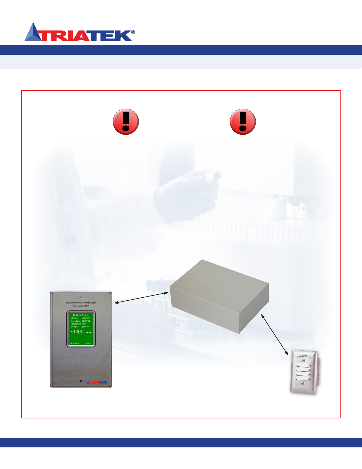
To preserve the accuracy of the calibration, the remote sensor
module MUST be installed no more than 10 feet from the
FMS-1650L controller module using the supplied interface cable.
Failure to do so could result in inaccurate differential pressure
readings.
The display module may be located up to 4000 feet from the
FMS-1650L controller module.
Distance not to exceed
4000 feet
Distance not
to exceed
10 feet
Due to continuous improvement, TRIATEK reserves the right to change product specifications without notice.
FMS-1650L
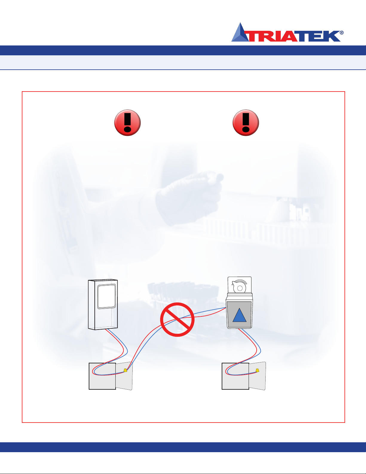
CAUTION
FAST ACTING
ELECTRONIC ACTUATOR
Controller Actuator
120/24VAC, 30Va Transformer
Supplied by Triatek
120/24VAC, 20Va Third Party
Transformer
CORRECT
Failure to follow the enclosed wiring diagrams could result in
damage to your equipment and could void your warranty. Wiring
diagrams can also be found at www.triatek.com.
Under no circumstances should a single transformer be split
between actuator and controller. Doing so will damage the
actuator, the transformer, the controller or all units. A single
120/24V 30Va transformer is required for the controller and a
separate 120/24V 20Va transformer is required for the actuator.
CORRECT
TRIATEK reserves the right to change product specifications without notice.

Due to continuous improvement, TRIATEK reserves the right to change product specifications without notice.
FMS-1650L
Due to continuous improvement, TRIATEK reserves the right to change product specifications without notice. Due to continuous improvement, TRIATEK reserves the right to change product specifications without notice.
GENERAL
Specifications
…………………………………………………………………………………………………………………………… 1 - 2
Part Number Guide ………………………………………………………………………………………………………………………… 2
Overview …………………………………………………………………………………………………………………………………… 3
MOUNTING/WIRING
FMS Case Dimensions …………………………………………………………………………………………………………………… 4
FMS Display Mounting Hole Pattern ……………………………………………………………………………………………………… 5
Controller Mounting Hole Pattern ………………………………………………………………………………………………………… 6
Remote Sensor Option ………………………………………………………………………………………………………………… 7 - 9
Remote Sensor Connector Strip ………………………………………………………………………………………………………… 10
Function Descripations …………………………………………………………………………………………………………………… 11
Analog Output to Modulated Air Controller …………………………………………………………………………………………… 12
Analog Input to Remote Pressure Sensor - 0 - 10V …………………………………………………………………………………… 13
Analog Input to Remote Pressure Sensor - 4-20mA Out …………………………………………………………………………… 14
Analog Input to 2 Remote Pressure Sensors - 0 - 10V Out ………………………………………………………………………… 15
Analog Input to 2 Remote Pressure Sensors - 4-20mA Out ………………………………………………………………………… 16
Adding Input to Temperature Sensor …………………………………………………………………………………………………… 17
Digital Input to Door Switch ……………………………………………………………………………………………………………… 18
Digital Input to Flow Switch ……………………………………………………………………………………………………………… 19
Digital Input to Occupancy Sensor ……………………………………………………………………………………………………… 20
Relay Output to Alarm …………………………………………………………………………………………………………………… 21
Relay Output to Warning ………………………………………………………………………………………………………………… 22
Relay Output 1 …………………………………………………………………………………………………………………………… 23
Relay Output 2 …………………………………………………………………………………………………………………………… 24
Power ……………………………………………………………………………………………………………………………………… 25
Isolated Power Supply …………………………………………………………………………………………………………………… 26
COMMUNICATIONS
Wiring ……………………………………………………………………………………………………………………………………… 27
General Wiring …………………………………………………………………………………………………………………………… 28
FMS-1650L PROGRAMMING
Basic Programming
………………………………………………………………………………………………………………… 30 - 33
Main Display Screen ……………………………………………………………………………………………………………………… 33
Main Display Screen …………………………………………………………………………………………………… 30 - 31
Configuring Isolation Room Controller ……………………………………………………………………………………… 31
Set Target Setpoints ………………………………………………………………………………………………………… 31
Setting Up the Analog Output ………………………………………………………………………………………… 31 - 32
Setting the Isolation Mode …………………………………………………………………………………………………… 32
Changing Display Settings ……………………………………………………………………………………………… 32 - 33
Built-In Diagnostics …………………………………………………………………………………………………………… 33
INSTALLATION MANUAL
Table of Contents
TRIATEK reserves the right to change product specifications without notice. TRIATEK reserves the right to change product specifications without notice.

Due to continuous improvement, TRIATEK reserves the right to change product specifications without notice.Due to continuous improvement, TRIATEK reserves the right to change product specifications without notice.
FMS-1650L
Due to continuous improvement, TRIATEK reserves the right to change product specifications without notice.
INSTALLATION MANUAL
Table of Contents
MODULE SETTINGS
Configuring Display Module Settings …………………………………………………………………………………………… 34 - 35
CLEANING THE DISPLAY
Cleaning the FMS-1650L ……………………………………………………………………………………………………………… 36
TRIATEK reserves the right to change product specifications without notice.

Due to continuous improvement, TRIATEK reserves the right to change product specifications without notice.
- 1 -
FMS-1650L
Due to continuous improvement, TRIATEK reserves the right to change product specifications without notice. Due to continuous improvement, TRIATEK reserves the right to change product specifications without notice.
Electrical
4 Analog Inputs …………………………………………………………………………………………………………………4-20mAdc, 0-5Vdc or 0-10Vdc
4 Analog Outputs ………………………………………………………………………………………………………………………… 0-5Vdc or 0-10Vdc
4 Digital Inputs ………………………………………………………………………………………………0-5Vdc or 0-24Vdc, Active-High or Active-Low
4 Relay Outputs ………………………………………………………………………………………………………………………………………1A@24Vdc
Input Impedance ……………………………………………………………………………………………………………………………………… 10k - 0 Ω
Output Impedance ……………………………………………………………………………………………………………………………………… Ω 0 -10k
Power Supply …………………… Class 2, 24Vac ±10%, 30VA universal 120/240 to 24 Vac, 60/50 Hz, step-down isolation transformer provided
Communications
LonWorks® FTT-10A peer-to-peer network ………………………………………………………………………Two-Wire Twisted Pair, FTT-10A signaling
Recommended Cable Type ………………………………………………………………………………………………………………………………………
• Level IV, 22AWG Unshielded Plenum UL Type CMP (Windy City 105540; Connet Air W22IP-2001; Metro Wire MWC-1000)
• Level IV, 22AWG Shielded Plenum UL Type CMP (Windy City 106500; Connet Air W22IP-2002; Metro Wire MWC-1002)
Touch Screen User Interface
LCD Size ……………………………………………………………………………………………………………………………………………3.2” diagonal
LCD Type ……………………………………………………………………………………………………………………………………………Transmissive
Resolution ………………………………………………………………………………………………………………………………………240 x 320 portrait
Viewing Area ……………………………………………………………………………………………………………………………50.60 mm x 66.80 mm
Color Depth …………………………………………………………………………………………………………………………………18-bit or 262K colors
Backlight Color ………………………………………………………………………………………………………………………………………………White
Luminous Intensity ………………………………………………………………………………………………………………………………min 2500 cd/m2
GENERAL
Specications
TRIATEK reserves the right to change product specifications without notice.
FMS-1650L -1-0-1
Case Style # of Remote Sensors
T = thin (flush) 1 = single sensor
S = surface 2 = dual sensor

Due to continuous improvement, TRIATEK reserves the right to change product specifications without notice.
- 2-
Due to continuous improvement, TRIATEK reserves the right to change product specifications without notice.
FMS-1650L
Due to continuous improvement, TRIATEK reserves the right to change product specifications without notice.
SUBHEAD
Specications
Mechanical
FMS-1650L Display Module Housing (Surface Mount) ……………………………………………………………………………………3”W x 5”H x 0.75”D
FMS-1650L Display Module Housing (Flush Mount) …………………………………………………………………………………5.6”W x 8.5”H x 0.75”D
FMS-1650L Controller Housing ………………………………………………………………………………………………………… 4.1”W x 6”H x 1.85”D
Environmental
Operating Temperature ……………………………………………………………………………………………………………… 32° to 125° F Operating
Operating Humidity ………………………………………………………………………………………………………… 10% - 95% RH, Non-condensing
Venturi Valve (Order Separately)
Diameter …………………………………………………………………………………………………………………………… 6”, 8”, 10”, 12”, 14” & 16”O.D.
CFM Range ……………………………………………………………………………………………………………………………………………… 30-2400
Materials ………………………………………………………………………………………………………… Aluminum, Stainless Steel, Heresite Coating
Sound Insulation ………………………………………………………………………………………………………………………………………… Optional
Actuation ………………………………………………………………………………………………………………………………… Electronic or Pneumatic
Part Number Guide
GENERAL
TRIATEK reserves the right to change product specifications without notice. TRIATEK reserves the right to change product specifications without notice.
FMS-1650L -1-0-1
Case Style # of Remote Sensors
T = thin (flush) 1 = single sensor
S = surface 2 = dual sensor

Due to continuous improvement, TRIATEK reserves the right to change product specifications without notice.
- 3-
FMS-1650L
Due to continuous improvement, TRIATEK reserves the right to change product specifications without notice.
The TRIATEK FMS-1650L Isolation Monitor
is an ultra-sensitive instrument used to control
and/or monitor air pressure in hospital rooms,
labs, and clean rooms. This unit is a precision
measuring system capable of measuring and
displaying air pressures down to 0.0001” WC.
It can be used to control pressures down to
0.001” WC. Features of the unit include:
• Digital display of pressure with a
programmable descriptor
• Full color touch screen
• audible and visual alarm annunciation
• Four relay outputs for transmitting alarm
conditions to a remote location such as a
central monitoring station
• Auxiliary analog inputs for use with
optional sensors
• Analog outputs used in control
applications
• Password protection of programmed
setup
• Optional keylock switch for isolation
select protection
• Optional LON communications.
The FMS-1650L is equipped with a full color
touch screen display and can be wiped clean
using a soft cloth without the use of harsh
chemicals. No decontamination requirements
are required for the proper operation of this
product.
There are three background screen colors
to indicate “Normal” when pressure is within
defined limits, “Caution” when pressure
is nearing an out-of-limits condition, and
“Alarm” when pressure is outside defined
acceptable limits. The pressure ranges for
these conditions are easily set by the user for
the specific installation when necessary. The
background screen colors provide overview of
room pressure conditions at a glance.
Alarm Conditions can be defined by the
user, in terms of desired pressure settings for
the room being monitored. When an alarm
condition occurs, it can be annunciated in
three user-definable ways: 1) on the display,
2) with an audible alarm, and 3) transmitted
via contacts to a remote monitoring station
and over network. The alarm can be set to
automatically reset when the unit has sensed
that the room pressure has returned to proper
limits, or it may be set to remain on until
manually reset. In either case, the attendant
can mute the audible alarm by touching the
OK button on the alarm popup.
The FMS-1650L provides four Relay
outputs that can be used for remote alarm
annunciation or pilot control functions. The
operation of each output can be configured by
the user to define the exact room air pressure
values above and below which the output will
operate. Delay times before activation can be
specified to minimize nuisance activation.
In many installations, it is important to have
other room variables such as temperature or
relative humidity to be displayed along with
room pressure.
The FMS-1650L provides for this by means
of Additional Analog Inputs which can be
configured for 4-20 ma current or for voltage
input signals. The input can be scaled as
needed to display correct values, and a
suitable descriptor can be applied.
The FMS-1650L provides Analog Outputs
which can be set up for voltage. It can be
programmed to be proportional output (AO-2,
AO-3 or AO-4) for providing a linear signal
to an automation system, or programmed
for PID floating point output (AO-1) for direct
control of damper actuators, speed drives,
etc.
The user can set up multiple access level
passwords to protect against unauthorized or
casual access to the FMS-1650L programmed
variables.
Room pressure selection of Positive,
Negative, or No Isolation is set using the
user menu or an optional Keylock Switch.
A LON Communications Interface enables
the unit to communicate room status
information to the building automation system.
GENERAL
Overview
TRIATEK reserves the right to change product specifications without notice.
Due to continuous improvement, TRIATEK reserves the right to change product specifications without notice.
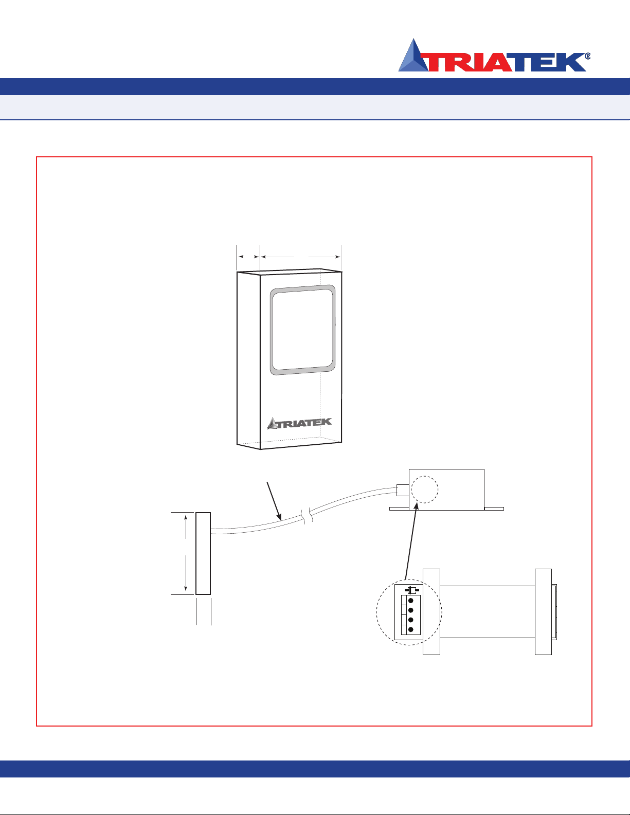
SUBHEAD
FMS Case Dimensions
FMS-1650L
Due to continuous improvement, TRIATEK reserves the right to change product specifications without notice.
- 4 -
3"
5"
3/4
"
3/4
"
®
Due to continuous improvement, TRIATEK reserves the right to change product specifications without notice.TRIATEK reserves the right to change product specifications without notice.
PWR LED
— + GND +V
MOUNTING/WIRING
TRIATEK reserves the right to change product specifications without notice.
Right Side
View
Left Angle
Side View
Control Unit
Adapter
(Inside Control Unit)
Recommended Cable Type:
Belden 1325A

Due to continuous improvement, TRIATEK reserves the right to change product specifications without notice.
SUBHEAD
FMS-1650L
Due to continuous improvement, TRIATEK reserves the right to change product specifications without notice.
- 5 -
Due to continuous improvement, TRIATEK reserves the right to change product specifications without notice.TRIATEK reserves the right to change product specifications without notice.
MOUNTING/WIRING
TRIATEK reserves the right to change product specifications without notice.
FMS Display Mounting Hole Pattern
The FMS-1650L display backplate may be mounted directly to a standard single-gang wall
box using the two slots along the centerline. Use the backplate as a template to mark the
mounting holes and the cable access hole at the center of the backplate.
Due to continuous improvement, TRIATEK reserves the right to change product specifications without notice.Due to continuous improvement, TRIATEK reserves the right to change product specifications without notice.
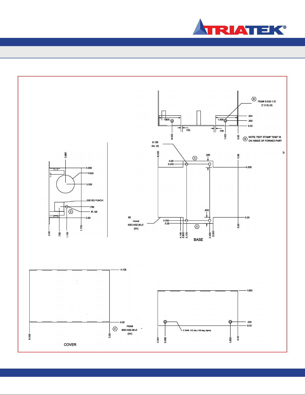
SUBHEAD
Controller Mounting Hole Pattern
FMS-1650L
Due to continuous improvement, TRIATEK reserves the right to change product specifications without notice.
- 6-
MOUNTING/WIRING
TRIATEK reserves the right to change product specifications without notice.TRIATEK reserves the right to change product specifications without notice. TRIATEK reserves the right to change product specifications without notice.

Due to continuous improvement, TRIATEK reserves the right to change product specifications without notice.
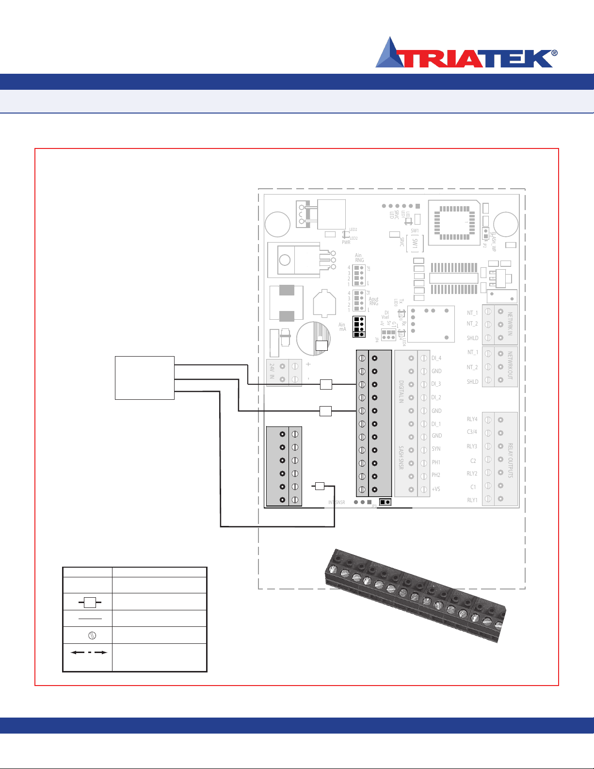
FMS-1650L’s ordered with a remote sensor
must be installed in the wall between the isola-
tion room and the adjoining corridor. Port P1
must be oriented towards the isolation room
and Port P2 toward the corridor. Please see
illustration on page 13. With this sensor orien-
tation a positive pressure value indicates that
the isolation room is positive with respect to
the corridor. A three conductor cable must
be connected between the remote sensor
and the display processor unit. Maximum
length of this cable is 4000 feet. The display
unit can be installed outside the room, at the
nurses station, in the engineering office, or at
any other location as needed.
Mounting Steps:
1. Cut opening in the wall of the isolation
room to receive the mounting enclosure
for the remote sensor electronics.
Nominal hole dimensions are 3 1
/8” h x
2”w.
2. Drill a 7/16” hole through the opposite wall
for the flow tube as shown.
3. Bring the 2-conductor signal wire through
the cut-out.
4. Knock out the back and one bottom
knock-out, then with the signal wire pulled
through the bottom hole into the box.
Mount the enclosure box in the opening
provided and secure with screw and
anchors. Seal around the edges of the
box with UL Classified Fire Sealant.
5. Push a length of flow tube through the
back hole on through the 7/16” hole in the
opposite wall.
6. Attach the flow tube to the sensor port,
then push the tube and sensor module
into place and secure to the mounting
enclosure with two 6-32 x 3/4 screws
supplied.
7. Install the louvered cover plate.
8. On the opposite side (corridor) attach the
flow tube to the barbed fitting of the flow
tube mounting plate.
9. Press the mounting plate into place,
allowing the excess tube length to go into
the wall space. Secure with the screws
and anchors.
10. Install the louvered cover plate.
11. For 4-20mA operation - At the FMS-
1650L connect the three leads from the
remote sensor to the terminals marked
+V “, “AI-1” and “GND”. Remote Sensor
“Vin” goes to terminal “+V”; “GND”
connects to “GND” and “Io” connects with
terminal “AI-1”.
Install jumper on pin 1 JP6 and JP3 see
diagram on page 14. (If not installed at
the factory.)
Mounting/Wiring
Remote Sensor Option
FMS-1650L
- 7-
TRIATEK reserves the right to change product specifications without notice.

Due to continuous improvement, TRIATEK reserves the right to change product specifications without notice.
Mounting/Wiring
Remote Sensor Option
FMS-1650L
- 8 -
TRIATEK reserves the right to change product specifications without notice. TRIATEK reserves the right to change product specifications without notice.
NC
NC
GND
NC
NC
Io
NC
GND
+Vin
NC
NC
GND
NC
NC
Io
NC
GND
+Vin
~
~
~
~
Remote Sensor Installation Detail
(Side View)
ISOLATION
ROOM
CORRIDOR
Stainless Steel
Mounting Plate
Gasket
Louvered Cover
Plate
Stainless Steel
Flow Tube
Mounting Plate Gasket
Thin Silicone Caulking
(apply around tube and between
stainless steel plate and wall to seal
unit penetration)
Terminal
For connection of transmitter to
FMS-1650L
Flow Tube
When Flow Tube mounting plate
is located directly opposite the
sensor, flow tubing must be cut as
short as possible to prevent kinks.
To FMS-1650L Controller
Wall Section
(cutaway view)
Orange wall bracket
to be installed first
by using the rotating
clamps for secure
wall attachment.

Due to continuous improvement, TRIATEK reserves the right to change product specifications without notice.
Mounting/Wiring
Remote Sensor Option
FMS-1650L
- 9 -
TRIATEK reserves the right to change product specifications without notice.
NC
NC
GND
NC
NC
Io
NC
GND
+Vin
NC
NC
GND
NC
NC
Io
NC
GND
+Vin
~
~
~
~
Remote Sensor Installation Detail
(Bottom View)
ISOLATION
ROOM
CORRIDOR Stainless Steel
Mounting Plate
Gasket Louvered Cover
Plate
Stainless Steel
Flow Tube
Mounting Plate
Gasket
Thin Silicone Caulking
(apply around tube and
between stainless steel
plate and wall to seal unit
penetration)
Terminal
For connection of
transmitter to
FMS-1650L
Flow Tube
When Flow Tube mounting plate
is located directly opposite the
sensor, flow tubing must be cut as
short as possible to prevent kinks.
To FMS-1650L
Controller
Wall Section
(cutaway view)
Rotating clamps secure
assembly to wall board
Due to continuous improvement, TRIATEK reserves the right to change product specifications without notice.
Mounting / Wiring
Remote Sensor Connector Strip
FMS-1650L
- 10 -
TRIATEK reserves the right to change product specifications without notice. TRIATEK reserves the right to change product specifications without notice.
AO_1
AO_2
AO_3
AO_4
AI_1
AI_2
AI_3
AI_4
GND
GND
+10v
+V
ANALOG IN
NT_1
NT_2
NETWRK OUT
DI_1
DI_2
DI_4
GND
GND
GND
PH1
PH2
+VS
SYN
+
-
24V IN
SASH SNSR
DIGITAL IN
RLY1
RLY2
RLY3
RLY4
C3/4
C2
C1
RELAY OUTPUTS
SHLD
DI_3
1
2
3
EXT.SNSR
SELECT
INT.SNSR
G
5v
+V
DI
SRVC
EXT.
SRVC
SNSR
FLASH_WP
+5v
GND
GND
GND
GND
1
SHLD
NETWRK IN
NT_2
NT_1
AUX PWR OUTPUT
PWR
ANALOG OUT
Vsel
1
SW1
RNG
4
1
2
3
1
LED1
1
JP2
LED
Ain
4
Aout
LED2
1
JP4
1
2
JP5
1
4
RNG
1
Tx
mA 3
LED3
LED4
JP7
Ain
1
1
JP6
Rx
* * ** * *
SW1
LED1
1
JP3
11
JP2
LED2
1
1
1
1
1
LED3 LED4
1
1
NC
No Connection to Field Wiring
Field Wiring w/space for Number
Internal Wiring
Screw Terminal
Wiring Guide Legend
Symbol Description
Air Flow To and From Unit
Between Room and Corridor
Remote
Sensor/
Transmitter
GND
Io
+Vin
The electrical connections to the FMS-1650L are made
via a convenient removable terminal block as shown
below. All wiring should conform to the Local Regulations
and National Electrical Code. Take care not to run
Sensor wiring in the same conduit as linevoltage or other
conductors that supply highly inductive loads such as
generators, motors, solenoids, contactors, etc. Use 22
AWG or larger.
Removable
Connector
for easy installation
of field wiring. Note:
The FMS remote sensor is an option
which must be specified at time of
purchase from factory.
Remote Sensor
Connector

Due to continuous improvement, TRIATEK reserves the right to change product specifications without notice.
Mounting / Wiring
Function Descriptions
FMS-1650L
- 11 -
TRIATEK reserves the right to change product specifications without notice.
Function Description
AUX Power Output Power supply outputs used for power auxiliary devices. Each is supply limited to 100
ma.
LON Communications LON FTT-10A Free Topology Network building automation system can access the sta-
tus and the configuration of the unit. Also used by configuration software to configure
unit.
Analog Output Unit has 4 Analog Outputs which can be configured for 0-5 VDC or 0-10VDC.
Analog Input Unit has 4 Analog Inputs which can be configured for 4-20 mA, 0-5VDC, or 0-10VDC.
Power The FMS-1650L Series can be powered by either 24 VAC or 24 VDC. A 120 VAC to
24 VAC Step Down Isolation Transformer is provided and recommended. This power
must be from a Class 2 supply only.
Digital Input The unit has 4 Digital Inputs with selectable pull-up voltages of 0V, +5V and +18V.
Relay Output The unit has 4 SPDT Relay outputs with normally open contacts.
Due to continuous improvement, TRIATEK reserves the right to change product specifications without notice.
Mounting / Wiring Remote Sensor
Analog Output to Modulated Air Controller
FMS-1650L
- 12 -
TRIATEK reserves the right to change product specifications without notice. TRIATEK reserves the right to change product specifications without notice.
AO_1
AO_2
AO_3
AO_4
AI_1
AI_2
AI_3
AI_4
GND
GND
+10v
+V
ANALOG IN
NT_1
NT_2
NETWRK OUT
DI_1
DI_2
DI_4
GND
GND
GND
PH1
PH2
+VS
SYN
+
-
24V IN
SASH SNSR
DIGITAL IN
RLY1
RLY2
RLY3
RLY4
C3/4
C2
C1
RELAY OUTPUTS
SHLD
DI_3
1
2
3
EXT.SNSR
SELECT
INT.SNSR
G
5v
+V
DI
SRVC
EXT.
SRVC
SNSR
FLASH_WP
+5v
GND
GND
GND
GND
1
SHLD
NETWRK IN
NT_2
NT_1
AUX PWR OUTPUT
PWR
ANALOG OUT
Vsel
1
SW1
RNG
4
1
2
3
1
LED1
1
JP2
LED
Ain
4
Aout
LED2
1
JP4
1
2
JP5
1
4
RNG
1
Tx
mA 3
LED3
LED4
JP7
Ain
1
1
JP6
Rx
* * ** * *
SW1
LED1
1
JP3
11
JP2
LED2
1
1
1
1
1
LED3 LED4
1
1
NC
No Connection to Field Wiring
Field Wiring w/space for Number
Internal Wiring
Screw Terminal
Wiring Guide Legend
Symbol Description
Air Flow To and From Unit
Between Room and Corridor
CONNECTIONS FOR POWERED OUTPUT
~
~
-
+
Air
Control
Modulator
+
-
+
-
Optional External
Transmitter
Power Supply
0-5v (JP7)
Jumper Setting
AI 1
AI 2
AI 3
AI 4
1
2
3
4
= JUMPER ON
Analog Input
0-10v (JP7)
AI 1
AI 2
AI 3
AI 4
JP7
1
2
3
4
Analog Input
4-20mA (JP6)
AI 1
AI 2
AI 3
AI 4
Analog Input
JP6
0-5v (JP5)
AO 1
AO 2
AO 3
AO 4
Analog Output
0-10v (JP5)
AO 1
AO 2
AO 3
AO 4
JP5
Analog Output
Note: 4-20mA can only be used if the
corresponding JP7 Analog Input Jumper
is set to OFF.
Note: Each Analog Input or Output value can be set independent of one another.
Example:
AI 1 can be set to 0-5v jumper OFF (JP7 PIN 1)
AI 2 can be set to 0-10v jumper ON (JP7 PIN 2)
AI 3 can be set to 4-20mA jumper ON (JP6 PIN 3) and jumper OFF (JP7 PIN 3)
AO 1 can be set to 0-10v jumper ON (JP5 PIN 1)
AO 2 0-5v can be set to 0-5v jumper OFF (JP5 PIN 2)
= JUMPER OFF
1
2
3
4
1
2
3
4
1
2
3
4
1
2
3
4
Purchased Separately
Purchased Separately
4-20mA Loop

Due to continuous improvement, TRIATEK reserves the right to change product specifications without notice.
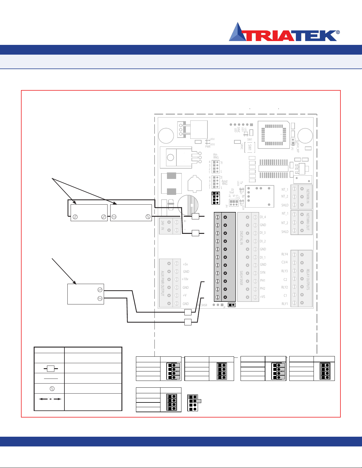
Mounting / Wiring
Analog Input to Remote Pressure Sensor - 0-10V Out
FMS-1650L
- 13 -
TRIATEK reserves the right to change product specifications without notice.
0-10V OUT
A
O
1
A
O
2
A
O
3
A
O4
A
I
A
I
A
I
A
I
G
ND
G
ND
+1
0v
+
V
A
NAL
OG
I
1
2
3
E
XT
S
N
SR
+
5v
G
ND
G
ND
G
ND
G
ND
AU
X PWR
OU
TP
U
A
NAL
OG
OUT
R
N
G
4
1
2
3
Ain
4
Aout
J
P
4
2
J
P
5
4
R
N
G
1
m
A
3
J
P
7
Ain
J
P
6
1
1
1
NC
No Connection to Field Wiring
Field Wiring w/space for Number
Internal Wiring
Screw Terminal
Wiring Guide Legend
Symbol Description
Air Flow To and From Unit
Between Room and Corridor
N
T
1
N
T
2
N
ETWRK
OUT
DI
DI
DI
G
ND
G
ND
G
ND
PH
1
PH2
+V
S
S
Y
N
+
-
24
V
I
N
S
A
S
H
S
N
S
DI
G
ITAL
R
LY
R
LY
2
R
LY
3
R
LY
4
C3
/4
C2
C1
R
ELAY
OU
TP
UT
S
HL
D
DI
E
XT
.S
N
S
S
ELE
C
INT
.S
N
S
G
5v
+
V
D
I
S
RV
C
S
RV
C
FLASH WP
1
S
HL
D
N
ETWRK
I
N
T
2
N
T
1
PWR
V
se
1
S
W
1
L
ED
1
J
P
2
L
E
D
L
ED
2
1
4
Tx
L
ED
3
L
ED
4
Rx
*
*
*
*
*
*
S
W
1
LED1
D
D
D
JP3
1
111111111111111111111111111
JP2
FL
FL
L
ED
2
1
LED3
E
E
E
LED4
E
E
E
1
111111111111111111111111111
-
IN
+
Pressure
Sensor
0-5v (JP7)
Jumper Setting
AI 1
AI 2
AI 3
AI 4
1
2
3
4
= JUMPER ON
Analog Input
0-10v (JP7)
AI 1
AI 2
AI 3
AI 4
JP7
1
2
3
4
Analog Input
4-20mA (JP6)
AI 1
AI 2
AI 3
AI 4
Analog Input
JP6
0-5v (JP5)
AO 1
AO 2
AO 3
AO 4
Analog Output
0-10v (JP5)
AO 1
AO 2
AO 3
AO 4
JP5
Analog Output
Note: 4-20mA can only be used if the
corresponding JP7 Analog Input Jumper
is set to OFF.
Note: Each Analog Input or Output value can be set independent of one another.
Example:
AI 1 can be set to 0-5v jumper OFF (JP7 PIN 1)
AI 2 can be set to 0-10v jumper ON (JP7 PIN 2)
AI 3 can be set to 4-20mA jumper ON (JP6 PIN 3) and jumper OFF (JP7 PIN 3)
AO 1 can be set to 0-10v jumper ON (JP5 PIN 1)
AO 2 0-5v can be set to 0-5v jumper OFF (JP5 PIN 2)
= JUMPER OFF
1
2
3
4
1
2
3
4
1
2
3
4
1
2
3
4

Due to continuous improvement, TRIATEK reserves the right to change product specifications without notice.
Mounting / Wiring
Analog Input to Remote Pressure Sensor - 4-20mA Out
FMS-1650L
- 14 -
TRIATEK reserves the right to change product specifications without notice. TRIATEK reserves the right to change product specifications without notice.
AO_1
AO_2
AO_3
AO_4
AI_1
AI_2
AI_3
AI_4
GND
GND
+10v
+V
ANALOG IN
NT_1
NT_2
NETWRK OUT
DI_1
DI_2
DI_4
GND
GND
GND
PH1
PH2
+VS
SYN
+
-
24V IN
SASH SNSR
DIGITAL IN
RLY1
RLY2
RLY3
RLY4
C3/4
C2
C1
RELAY OUTPUTS
SHLD
DI_3
1
2
3
EXT.SNSR
SELECT
INT.SNSR
G
5v
+V
DI
SRVC
EXT.
SRVC
SNSR
FLASH_WP
+5v
GND
GND
GND
GND
1
SHLD
NETWRK IN
NT_2
NT_1
AUX PWR OUTPUT
PWR
ANALOG OUT
Vsel
1
SW1
RNG
4
1
2
3
1
LED1
1
JP2
LED
Ain
4
Aout
LED2
1
JP4
1
2
JP5
1
4
RNG
1
Tx
mA 3
LED3
LED4
JP7
Ain
1
1
JP6
Rx
* * ** * *
SW1
LED1
1
JP3
11
JP2
LED2
1
1
1
1
1
LED3 LED4
1
1
4-20mA OUT
NC
No Connection to Field Wiring
Field Wiring w/space for Number
Internal Wiring
Screw Terminal
Wiring Guide Legend
Symbol Description
Air Flow To and From Unit
Between Room and Corridor
Remote
Pressure
Sensor
Io
+Vin
GND
0-5v (JP7)
Jumper Setting
AI 1
AI 2
AI 3
AI 4
1
2
3
4
= JUMPER ON
Analog Input
0-10v (JP7)
AI 1
AI 2
AI 3
AI 4
JP7
1
2
3
4
Analog Input
4-20mA (JP6)
AI 1
AI 2
AI 3
AI 4
Analog Input
JP6
0-5v (JP5)
AO 1
AO 2
AO 3
AO 4
Analog Output
0-10v (JP5)
AO 1
AO 2
AO 3
AO 4
JP5
Analog Output
Note: 4-20mA can only be used if the
corresponding JP7 Analog Input Jumper
is set to OFF.
Note: Each Analog Input or Output value can be set independent of one another.
Example:
AI 1 can be set to 0-5v jumper OFF (JP7 PIN 1)
AI 2 can be set to 0-10v jumper ON (JP7 PIN 2)
AI 3 can be set to 4-20mA jumper ON (JP6 PIN 3) and jumper OFF (JP7 PIN 3)
AO 1 can be set to 0-10v jumper ON (JP5 PIN 1)
AO 2 0-5v can be set to 0-5v jumper OFF (JP5 PIN 2)
= JUMPER OFF
1
2
3
4
1
2
3
4
1
2
3
4
1
2
3
4

Due to continuous improvement, TRIATEK reserves the right to change product specifications without notice.
Mounting / Wiring
Analog Input to 2 Remote Pressure Sensors - 0-10V Out
FMS-1650L
- 15 -
TRIATEK reserves the right to change product specifications without notice.
A
O
1
A
O
2
A
O
3
A
O4
A
I
A
I
A
I
A
I
G
ND
G
ND
+1
0v
+
V
A
NAL
OG
I
1
2
3
E
XT
.S
N
S
S
ELE
C
E
XT
S
N
SR
+
5v
G
ND
G
ND
G
ND
G
ND
AU
X PWR
OU
TP
U
A
NAL
OG
OUT
R
N
G
4
1
2
3
Ain
4
Aout
J
P
4
2
J
P
5
4
R
N
G
1
m
A
3
J
P
7
Ain
J
P
6
1
1
N
T
1
N
T
2
N
ETWRK
OUT
DI
DI
DI
G
ND
G
ND
G
ND
PH
1
PH2
+V
S
S
Y
N
+
-
24
V
I
N
S
A
S
H
S
N
S
DI
G
ITAL
R
LY
R
LY
2
R
LY
3
R
LY
4
C3
/4
C2
C1
R
ELAY
OU
TP
UT
S
HL
D
DI
.SNS
G
5v
+
V
D
I
S
RV
C
S
RV
C
FLASH WP
S
HL
D
N
ETWRK
I
N
T
2
N
T
1
PWR
V
se
1
S
W
1
L
ED
1
J
P
2
L
E
D
L
ED
2
1
4
Tx
L
ED
3
L
ED
4
Rx
*
*
*
*
*
*
S
W
1
LED1
D
D
D
JP3
1
111111111111111111111111111
JP2
FL
FL
L
ED
2
1
LED3
E
E
E
LED4
E
E
E
1
111111111111111111111111111
INT
NC
No Connection to Field Wiring
Field Wiring w/space for Number
Internal Wiring
Screw Terminal
Wiring Guide Legend
Symbol Description
Air Flow To and From Unit
Between Room and Corridor
T
~
~
-
+
Pressure
Sensor 1
IN
~
~
~
~
-
IN
Pressure
Sensor 2
+
0-10V OUT
0-5v (JP7)
Jumper Setting
AI 1
AI 2
AI 3
AI 4
1
2
3
4
= JUMPER ON
Analog Input
0-10v (JP7)
AI 1
AI 2
AI 3
AI 4
JP7
1
2
3
4
Analog Input
4-20mA (JP6)
AI 1
AI 2
AI 3
AI 4
Analog Input
JP6
0-5v (JP5)
AO 1
AO 2
AO 3
AO 4
Analog Output
0-10v (JP5)
AO 1
AO 2
AO 3
AO 4
JP5
Analog Output
Note: 4-20mA can only be used if the
corresponding JP7 Analog Input Jumper
is set to OFF.
Note: Each Analog Input or Output value can be set independent of one another.
Example:
AI 1 can be set to 0-5v jumper OFF (JP7 PIN 1)
AI 2 can be set to 0-10v jumper ON (JP7 PIN 2)
AI 3 can be set to 4-20mA jumper ON (JP6 PIN 3) and jumper OFF (JP7 PIN 3)
AO 1 can be set to 0-10v jumper ON (JP5 PIN 1)
AO 2 0-5v can be set to 0-5v jumper OFF (JP5 PIN 2)
= JUMPER OFF
1
2
3
4
1
2
3
4
1
2
3
4
1
2
3
4
Purchased Separately
Table of contents
Popular Medical Equipment manuals by other brands


Getinge
Getinge Arjohuntleigh Nimbus 3 Professional Instructions for use

Mettler Electronics
Mettler Electronics Sonicator 730 Maintenance manual

Pressalit Care
Pressalit Care R1100 Mounting instruction

Denas MS
Denas MS DENAS-T operating manual

bort medical
bort medical ActiveColor quick guide

AccuVein
AccuVein AV400 user manual


