Tridekon Cropsaver User manual

OWNERS MANUAL
Tridekon
RR# 2
Neepawa, MB
R0J 1H0
Ph: (204) 966-3469
1-866-292-6115
Fax: (204) 966-3335
Email: [email protected]
www.tridekon.com
Read and understand this manual prior to installation or use of Tridekon Cropsavers

Statement of Policies
Shipping Claims
It is the original buyers/dealers responsibility to check that all goods have been received as ordered
Any claims for shipping errors, damage or loss upon delivery must be reported within 15 days of the
delivery date.
Warranty Information
• To obtain warranty service you must rst contact us to determine the problem and the most appropriate
solution for you.
• This warranty applies to the physical goods, and only for physical goods, purchased from Tridekon –
labour will not be covered.
• This warranty covers any defects in material or workmanship under normal use during the warranty
period.
• During the warranty period Tridekon will replace at no charge products or parts of a product that proves
defective because of improper material or workmanship under normal use and maintenance.
• The warranty period is one year after original purchase date.
• All item(s) returned for warranty consideration, inspection, repair, etc. must be shipped prepaid.
• All returns must be accompanied by a Return Authorization Form from Tridekon.
Shipping Charges
Customers are responsible for all shipping charges on any product. Tridekon uses multiple shipping
companies to ensure the lowest cost.
Acceptance
By placing an order with Tridekon the purchaser consents to the terms and conditions contained herein
and upon Tridekon providing the products ordered, these terms and conditions shall form an essential
part of the contract between the parties.
Installation Notice
The user of Tridekon Cropsavers are installing these products to their machines at their own risk.
Tridekon will not be responsible for damages resulting from improper installation.
Cropsavers® is a registered trade mark of Tridekon Ltd. © 2012 Tridekon Ltd. All rights reserved
Safety Signs
• Keep safety signs clean and legible at all times.
• Replace safety signs that are missing or have become illegible.
• Replaced parts that displayed a safety sign should also display the current sign.
• Safety signs are available from your authorized Dealer or from Tridekon.

TABLE OF CONTENTS
How Your Cropsavers Are Shipped ................................................................................................... Page 4
Lock-up Pin Warning ..............................................................................................................................Page 5
Crop Height Adjustment ......................................................................................................................Page 5
Fine Tuning Installation.........................................................................................................................Page 5
Cropsaver Parts Assembly Drawing..................................................................................................Page 6
Cropsaver Parts List ................................................................................................................................Page 7
Mounting Your Cropsavers ..................................................................................................................Page 8 to 12
Setting And Adjusting Your Cropsavers..........................................................................................Page 13
Removing Your Cropsavers..................................................................................................................Page 14
QR Code Link To Installation Video ...................................................................................................Page 15
Frequently Asked Questions ...............................................................................................................Page 15-16
Attached: Bolt-on information and instructions
Air lift kit instructions (if equipped)
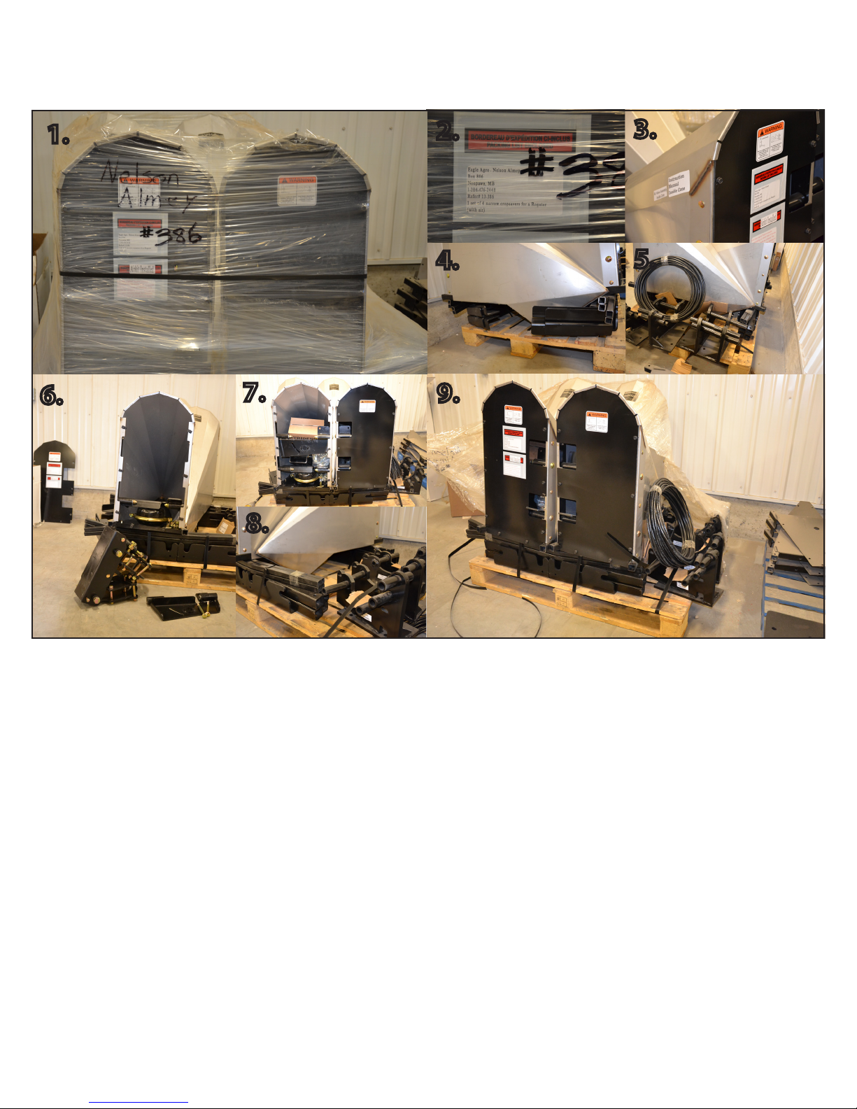
HOW YOUR CROPSAVERS ARE SHIPPED
2.
4. 5.
7.
8.
9.
1. 3.
6.
1. Your Cropsavers will arrive at your location wrapped and strapped to a shipping skid. Note the sticker
and reference numbers on the shipment.
2. The shipping label tells you the location it was shipped to and the contents of the skid. It also tells you
the dealer purchase order number and the Tridekon reference number. These are important when
dealing with either party.
3. The marked Cropsaver cone contains the owners manual and extra accessories (ie: air lift kit ttings, if
ordered)
4. At the bottom of the skid under the Cropsaver cones are the mounting arms and deector arms.
5. Bolt-on brackets can be found on the bottom of the pallet as well. (note: larger bolt-on brackets may
be packed on top of the Cropsaver cones.
6. Remove the back panels of the Cropsavers to remove inner quick attach brackets.
7. Behind the back panel of the marked cone (in picture 3) you will nd the instruction manual and air
lift ttings (if equipped).
8. Outer quick attach brackets are found at the bottom of the skid.
9. Unwrapped Cropsaver order, note location of the various parts
Page 4

WARNINGS
1. Remove lock-up pin for eld position, damage will occur if pins are placed back in bracket.
Failure to remove pins during eld operation will restrict Cropsaver lift and void warranty.
2. Check the 3/8” by 7” lock bolt on a regular basis to ensure it is still intact.
It is required to keep the Cropsaver from bouncing out of the outer quick attach bracket.
If maximum lift is exceeded it will act as a shear pin.
k
CROP HEIGHT ADJUSTMENT
Run the bottom tip of the Cropsavers one third of the way up from the height of the plant. Allow a couple
of inches for tire impression. The lowest height of crop that Cropsavers can eectively divide is 20”.
2/3
1/3
Some sets of Cropsavers will come with extra length on the mounting arms to accommodate dierent
tire and rim sizes. Some trimming of the arms may be required to get the Cropsavers in their optimal
position. Cropsavers should be no closer than 1.5”away from the front of the tire and no further that 10” away.
Bending of the deector arms may be required to avoid interference with your sprayer.
Deector arms should be no closer than 4” from the tire to avoid contact.
FINE TUNING THE INSTALLATION
Page 5
k
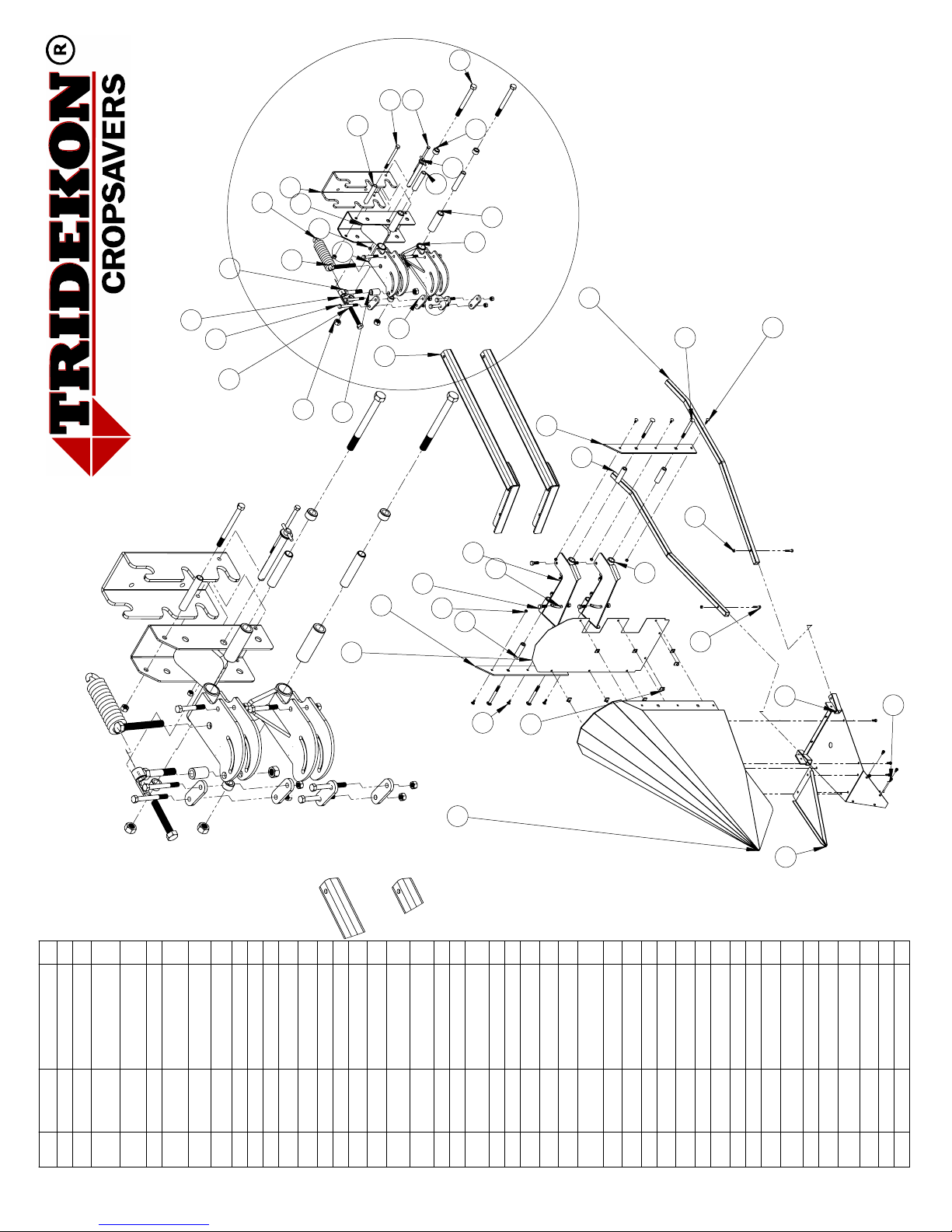
1.
2.
4
36
12
10
42
11
31
23
24
32
45
28
26
33
16
25
40
20
38
27
30
29
17
44
39
19
22
21
18
3
41
8
35
14
43
2
13
5
1
37
6
9
15
7
34
ITEM
NO.
PART
NUMBER
DESCRIPTION
QTY.
1
1-csp-07
Cropsaver Plus shell
1
2
8-csp-07
Cropsaver floor
panel
1
3
42-csp-07
reinforcement plate
2 1/2" x 22" right hand
1
4
41-csp-07
reinforcement plate
2 1/2" x 22" left hand
1
5
53-csp-07
reinforcement tip
1
6
52-csp-07
hinge plate for right
hand cropsaver
2
7
50-csp-07
1" d.o.m. .240 wall x 3
3/4" long
4
8
36-csp-07
1/2" carriage bolt x 5
1/2" long
4
9
37-csp-07
1/2" flat washer
4
10
13-csp-07
1/2" nylon locknut
15
11
43-csp-07
Right hand arm
2
12
45-csp-07
hexbolt 1/2" x 1 1/2"
long
4
13
34-csp-07
5/16" hexbolt x 3/4"
long
10
14
39-csp-07
5/16" nut
12
15
33-csp-07
Backwall Panel
1
16
25B-csp-07
Top hinged clevis
right
1
17
26A-csp-07
Lower hinged clevis
right
1
18
23-csp-07
1 1/2" nylon bushing
4 3/4" long
2
19
21-csp-07
1" d.o.m. x .120 wall x
4 7/8" long
2
20
20-csp-07
inner quick atach
1
21
24-csp-07
3/4" hexbolt 8" long
2
22
22-csp-07
1 1/4" d.o.m. bushing
x 3/4" long
4
23
10-csp-07
3/4" nylon locknut
3
24
7-csp-07
3/4" x4 1/2" long bolt
1
25
5-csp-07
coil spring hooked
3/4" nut
1
26
6-csp-07
Eyebolt 3/4" x 4" long
1
27
14-csp-07
1/2" pipe x 4 7/8"
long
1
28
9-csp-07
1 1/4" d.o.m. .240
bushing x 2" long
1
29
15-csp-07
1/2" hexbolt x 6" long
1
30
12-csp-07
1/2" bolt x 3 1/2" long
2
31
17-csp-07
1 1/2" clamp plate
4
32
16-csp-07
1/2" hexbolt x 4 1/2"
long
4
33
11-csp-07
3/4" adjustment bolt
x 6" long
1
34
40-csp-07
5/16" carriage bolt
4
35
46-csp-07
5/16" carriage bolt x
1" long
2
36
4-csp-07
5/16" nylon locknut
6
37
54-csp-07
Clip
8
38
19-csp-07
Outer quick attach
bracket
1
39
27-csp-07
3/8" hexbolt 7" long (
lock bolt )
1
40
28-csp-07
3/8" nylon locknut
1
41
2L-csp-07
Extention deflector
arm - left
1
42
2R-csp-07
Extention deflector
arm - right
1
43
3-csp-07
5/16" hexbolt x 1 1/2"
long
2
44
30-csp-07
3/4" lock pin
1
45
29-csp-07
#11 hitchpin
1
THE INFORMATION CONTAINED IN THIS DRAWING IS THE
SOLE PROPERTY OF TRIDEKON. ANY REPRODUCTION IN
PART OR AS A WHOLE WITHOUT THE WRITTEN PERMISSION
OF TRIDEKON IS PROHIBITED
Page 6

CROPSAVER PARTS LIST
Parts # # per cone
1-csp-07 1 Crop $aver Plus shell
8-csp-07 1 Crop $aver Plus floor panel
33-csp-07 1 backwall panel
53-csp-0 1 reinforcement tip (not shown on parts overview)
41-csp-07 1 reinforcement plate 2 1/2" x 22" left hand
42-csp-07 1 reinforcement plate 2 1/2" x 22" right hand
51-csp-07 2 hinge plates for left hand Crop $aver
52-csp-07 2 hinge plates for right hand Crop $aver
2L-csp-07 1 Extended deflector arms- left
2R-csp-07 1 Extended deflector arms- right
19-csp-07 1 Outer quick attach bracket
20-csp-07 1 Inner quick attach bracket
25-csp-07 1 top hinged clevis L/R
26-csp-07 1 Lower hinged clevis L/R
6-csp-07 1 eyebolt 3/4" x 4" long
5-cps-07 1 coil pull spring hooked 3/4" female thread
9-csp-07 1 3/4" ID bushing x 2"long
11-csp-07 1 Adjustment bolt 3/4"x6 with 3/4" jamnut
14-csp-07 4 1/2" ID bushing- spacer 4 7/8" length
17-csp-07 4 1 1/2" x 4" x 3/8" clamp plate
22-csp-07 4 steel 3/4" ID x 3/4" long spacers
27-csp-07 1
lockbolt 3/8" x 7" long
29-csp-07 1 # 11 hitchpin
30-csp-07 1 3/4" x 7" long lock pin
43-csp-07 2 arms for right hand Crop $aver *
44-csp-07 2 arms for left hand Crop $aver *
50-csp-07 1 1/2" ID x 4" long
21-csp-07 2 Nylon/ steel lined bushing
4-cps-07 2 5/16" nylon locknut
7-csp-07 1 3/4" x 4 1/2" long bolt
10-csp-07 3 3/4" nylon locknut
12-csp-07 2 1/2" bolt x 3 1/2" length
13-csp-07 11 1/2" nylon locknut
15-csp-07 1 1/2" hexbolt x 6" long + 1/2" nylon locknut
16-csp-07 4 1/2" hexbolt x 4 1/2" long
3-csp-07 2 5/16" x 1 1/2"
24-csp-07 2 3/4" hexbolt x 8" long
28-csp-07 1 3/8" nylon locknut
34-csp-07 8 5/16" x 3/4" hexbolt
35-csp-07 2 5/16" lock washers
36-csp-07 4 1/2" carriage bolts x 5 1/2" long
37-csp-07 2 1/2" flat washers
39-csp-07 14 5/16" nylon locknuts
40-csp-07 6 5/16" carriage bolts
45-csp-07 4 hexbolt 1/2" x 1 1/2" long
46-csp-07 1 5/16" carriage bolts X 1" long
54-csp-07 8 Back wall pins
Description
Page 7
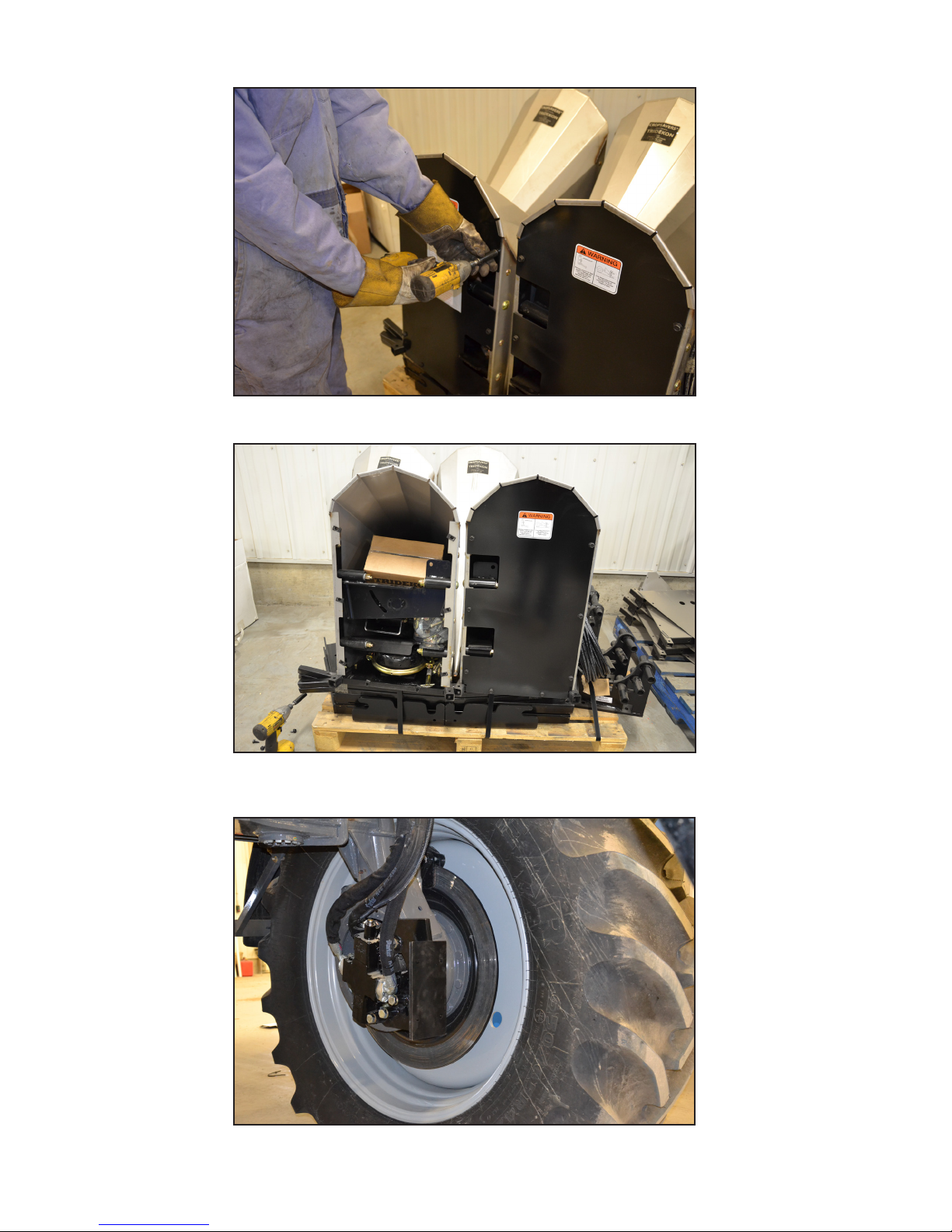
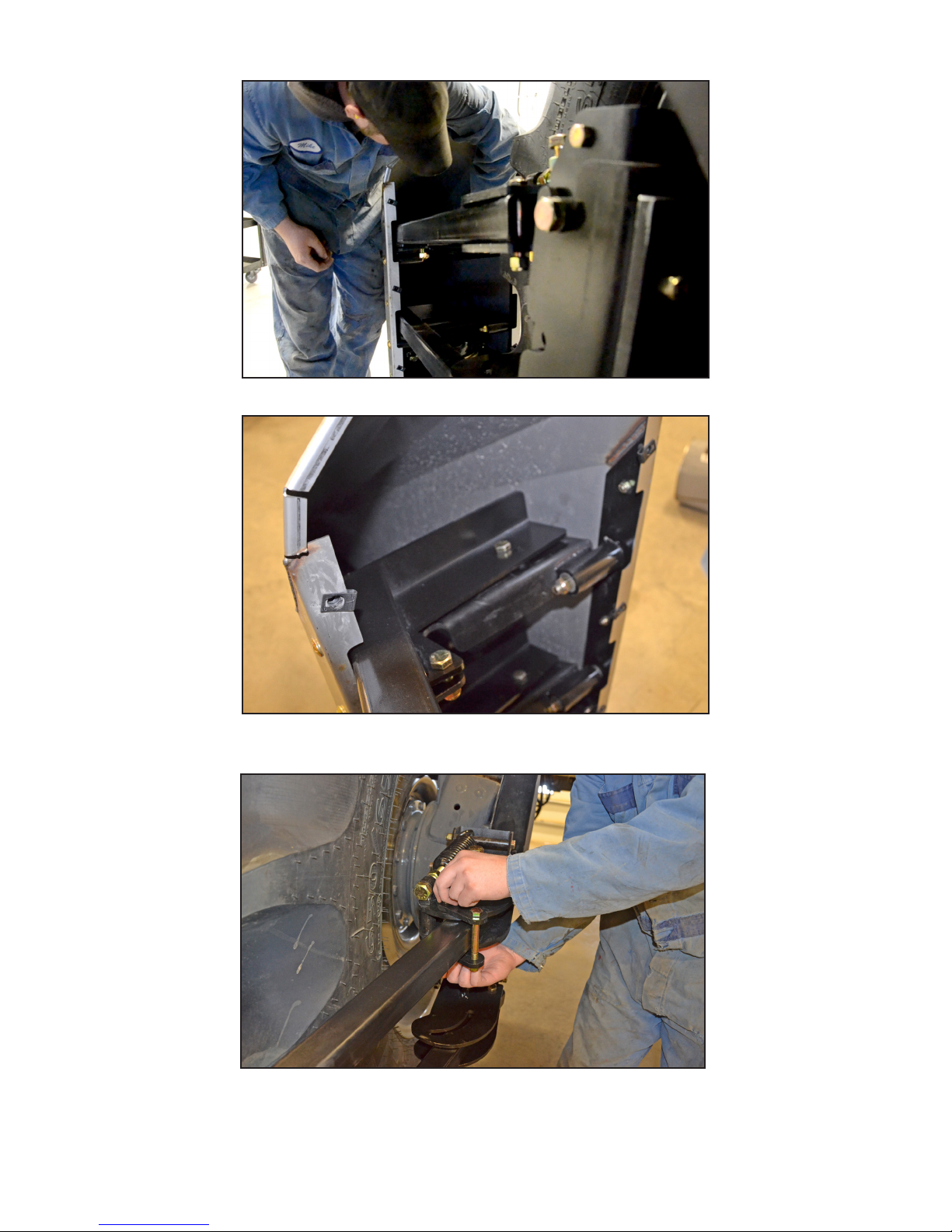
MOUNTING YOUR CROPSAVERS
1.
Remove back panels of Cropsavers.
Parts and accessories stored in Cropsaver cone for shipping.
Remove top pivot plate to remove inner quick attach brackets.
2.
3.
Mount bolt-on kit to your sprayer. Note there will be additional mounting instructions
for each individual sprayers. Follow those instructions to mount the bolt-on kit.
Page 8
g

MOUNTING YOUR CROPSAVERS
4.
Using supplied bolts (specied in the bolt-on instruction page) bolt the outer quick attach bracket
to the bolt-on bracket. Bolt-on bolts are found in a hardware bag in cone shown in picture # 2.
5.
Place the Cropsaver cone on a 5 gallon pail and bring it close to the wheel.
6.
Lower the inner quick attach assembly into the outer quick attach. Secure in place with 3/8 lock bolt.
Page 9
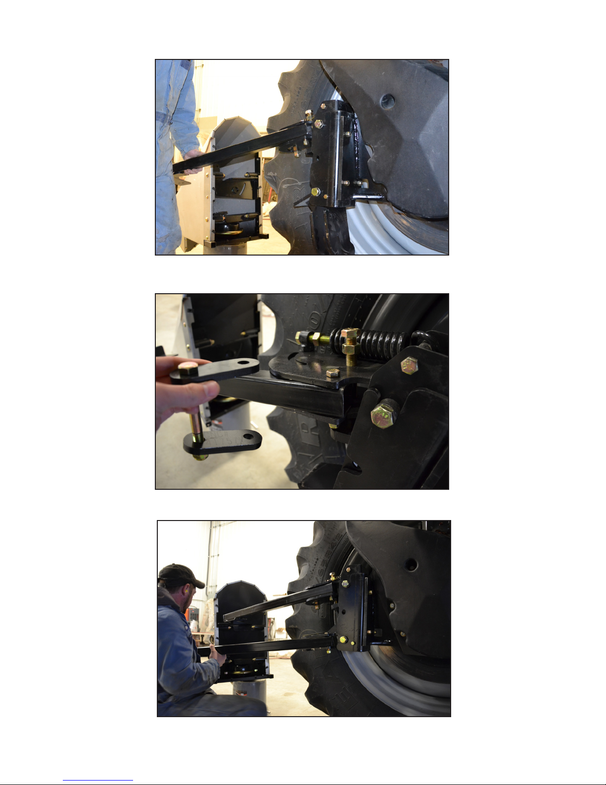
MOUNTING YOUR CROPSAVERS
7.
8.
Bolt arms into outer quick attach assembly. Arm and Deector arm bolts are found in a bag in each cone.
Leave these bolts loose temporarily until nal adjustments are complete.
Temporarily leave o clamp plates (shown above) until nal adjustments are complete.
9.
Guide arms into Cropsaver cone.
Page 10
MOUNTING YOUR CROPSAVERS
10.
Bolt arms into hinge plates. Note bolts holding arms on are kept loose at this point in time to allow for alignment.
11.
12.
Adjust cone to align it to the sprayer tire – the cone end pivots where the arms
bolt to the pivot plates. Make adjustments as described in step 12 simultaneously.
Arms can be moved back and forth horizontally to align Cropsaver to wheel. Cropsaver is properly aligned when arms are
no closer that 1”away from the side of the tire, and cone is covering the entire width of the tire in the front. When Cropsaver
is in correct place use clamp plates to lock Cropsaver in required position. Tighten all bolts in picture 7 and 11 at this time.
k
k
Page 11

MOUNTING YOUR CROPSAVERS
13.
Ensure all bolts are tightened after adjustments.
Insert deector arms and bolt into place. Deector arms can be shortened or re-bent to
t individuals sprayers better. Bolts found in Arm and Deector arm bolts bag.
14.
15.
Install back panel to complete installation. If ordered with the air lift kit
option, leave back panel o until air installation is complete. Page 12

SETTING AND ADJUSTING YOUR CROPSAVERS
Adjust spring tension to set the oating weight of the Cropsaver. Tighten jam nut against
the spring as picture shows so the spring doesn’t slide and Cropsaver oats properly.
Although it depends on conditions Tridekon recommends the tension to be
set so it takes about 5lbs of lift to lift the tip of the cone.
Use this bolt to set the height of the Cropsaver. Set the height with this bolt before setting the spring tension.
See Crop Height Adjustment section (Page 5) for further instruction. Tighten jam nut once adjusted.
1.
2.
3.
Page 13
Note: Cropsaver doesn’t need to be centered in-front of the tire – as long as it covers the entire width
of the tire. The back panel of the Cropsaver should be 90° to the sidewall of the tire.
f

REMOVING CROPSAVERS USING QUICK ATTACH
Lay pin ahead of hole used for lock-up. This will reduce the amount you have to lift
the Cropsaver while keeping it unlocked and free to be removed.
Remove 3/8” lock bolt then with two people, lift the tip of the Cropsaver and on the
arms. Pivot the bottom out rst then pull the top out.
Note if equipped with air lift disconnect the quick couplers rst.
f
1.
2.
Page 14

FREQUENTLY ASKED QUESTIONS
Page 15
INSTALLATION VIDEO
You can nd installation videos on our website or
go directly to them by scanning this QR code.
tridekon.com
1. I am still trampling crop. What is wrong?
You may be running the Cropsaver too low, raise the divider up . See page 5 for instruction.
2. How fast can I drive with the dividers on?
Generally speed does not matter. In some crops (ie: oats and barley) slow down depending on how ripe the
crop is.
3. Does driving quickly with Cropsavers do damage to the crop?
With the Cropsavers set at the correct crop height no damage will occur. However if your Cropsavers are set
too low some damage may occur.
4. Doesn’t the canopy stay open after the rst cone?
No, the crop waves back. The rear dividers are required to reopen the canopy.
5. How high can the dividers lift?
To the centre of the wheel diameter.
LOCKING THE CROPSAVERS UP
Manually lift the Cropsaver and insert the lock up pin to hold the Cropaver up.
If airlift is installed raise the cones fully and insert the lock up pin. Lock up pin shown in diagram.
k

FREQUENTLY ASKED QUESTIONS
Page 16
6. How low of a crop can you divide?
Minimum crop height is 20 inches.
7. How heavy should I set the resistance of the cones?
It should take 5-10 lbs of force to lift the tip of the Cropsaver when set properly.
8. What happens if I set the resistance too light?
The dividers will bounce around and can cause damage.
9. I am snapping bolts.
The dividers may be set too light, they will bounce around. OR: Going through heavy canopy (eg: podded
canola) will snap bolts.
10. How far in front of the tire should the cone be?
No less than 1.5” and no further than 10”.
11. How high should we run the dividers?
1/3 of the height of the crop from the lowest point of the divider not the tip.
12. Can I follow tram lines from earlier in the season?
You have to be careful doing this as there may be ruts left from the original pass. Cropsavers will not
bottom out and lift up in a rut, they can catch on the sides of the rut and a run-over could occur.
13. When I turn the wheels of my machine the Cropsaver cones drop down?
The tires pivot when the wheel is turned, the Cropsavers will move down slightly this is normal on some
machines.
14. Does my Cropsaver cone have to be perfectly centered with the tire?
No, as long as the Cropsaver cone covers the entire width of the tire it can be o centre.
15. Do Cropsavers work in canola?
Yes, if the canola is owering or in the early podding stage it is dividable. However if the crop is tangled ie:
fully podded or lodged and you are unable to walk through it, it will not divide very well.
16. Is there an easy way to remove the Cropsavers?
Yes, please refer to page 14 of the owners manual or refer to the Cropsaver Video section of tridekon.com.
It’s also possible to nd a balance point on your Cropsaver arms and weld in a link so you can use a fork lift
to carry the Cropsavers.
Table of contents
Popular Farm Equipment manuals by other brands

Schaffert
Schaffert Rebounder Mounting instructions

Stocks AG
Stocks AG Fan Jet Pro Plus 65 Original Operating Manual and parts list

Cumberland
Cumberland Integra Feed-Link Installation and operation manual

BROWN
BROWN BDHP-1250 Owner's/operator's manual

Molon
Molon BCS operating instructions

Vaderstad
Vaderstad Rapid Series instructions


