Tridonic EM powerLED BASIC FX lp 75 W User manual
www.tridonic.com 1
Subject to change without notice. Information provided without guarantee.
Data sheet 12/20-EM083-11
Emergency lighting units
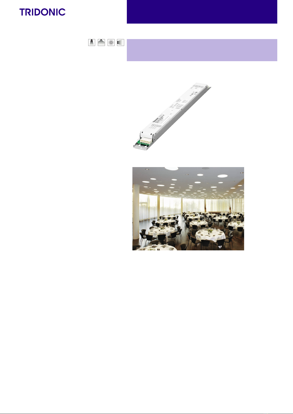
EM powerLED
Product description
• Fixed output LED Driver for mains operation
• Emergency lighting LED Driver with manual test function
• For self-contained emergency lighting
• For LED modules with a forward voltage of 50 – 220 V
• For luminaire installation
• Low profile casing (21 x 30 mm)
• 5 years guarantee
Properties
• 6 – 75 W output power
• Constant current LED operation
• Adjustable output current between 80 and 400 mA via ready-
2mains Programmer or I-SELECT 2 plugs
• Integrated emergency lighting unit
• 1 or 3 hr rated duration
• Automatic shutdown of output if LED load is out of range
• Green charge status display LED
• Electronic multi-level charge system
• Polarity reversal protection for battery
• Deep discharge protection
• Short-circuit-proof battery connection
Batteries
• High-temperature cells
• NiCd or NiMH batteries
• D, Cs or LA cells
• 4-year design life
• 1-year guarantee
• For battery compatibility refer to table „Battery selection“
È
Standards, page 6
Wiring diagrams and installation examples, page 6
EM powerLED BASIC FX lp 75 W
Combined emergency lighting LED Driver
www.tridonic.com 2
Subject to change without notice. Information provided without guarantee.
Data sheet 12/20-EM083-11
Emergency lighting units
EM powerLED
EL
Technical data
Rated supply voltage 220 – 240 V
AC voltage range 198 – 264 V
Mains frequency 50 / 60 Hz
Typ. current (at 230 V, 50 Hz, full load)1380 mA
Leakage current (at 230 V, 50 Hz, full load)1< 250 µA
Max. input power 85 W
Typ. λ (at 230 V, 50 Hz, normal operation) 0.98
Overvoltage protection 320 V (for 48 h)
Battery charging time < 24 h
U-OUT 280 V
Typ. input current in no-load operation 1 hr
(charging)
16 mA
Typ. input current in no-load operation 3 hr
(charging)
18 mA
Typ. input power in no-load operation 1 hr
(charging)
2 W
Typ. input power in no-load operation 3 hr
(charging)
2.4 W
In-rush current (peak / duration) 26 A / 280 µs
THD (at 230 V, 50 Hz, full load)1< 10 %
Time to light < 0.5 s from detection of emergency
event
Starting time (mains o) < 1.3 s
Starting time (stand-by) < 250 ms
Turn o time (at 230 V, 50 Hz, full load) < 50 ms
Max. output current peak (non-repetitive) ≤ output current + 35 %
Output LF current ripple (< 120 Hz) ± 5 %
Output current tolerance ± 5 %
Ambient temperature ta6-5 ... +50 °C
Max. casing temperature tc 75 °C
Mains surge capability (between L - N) 1 kV
Mains surge capability (between L/N - PE) 2 kV
Surge voltage at output side (against PE) 2 kV
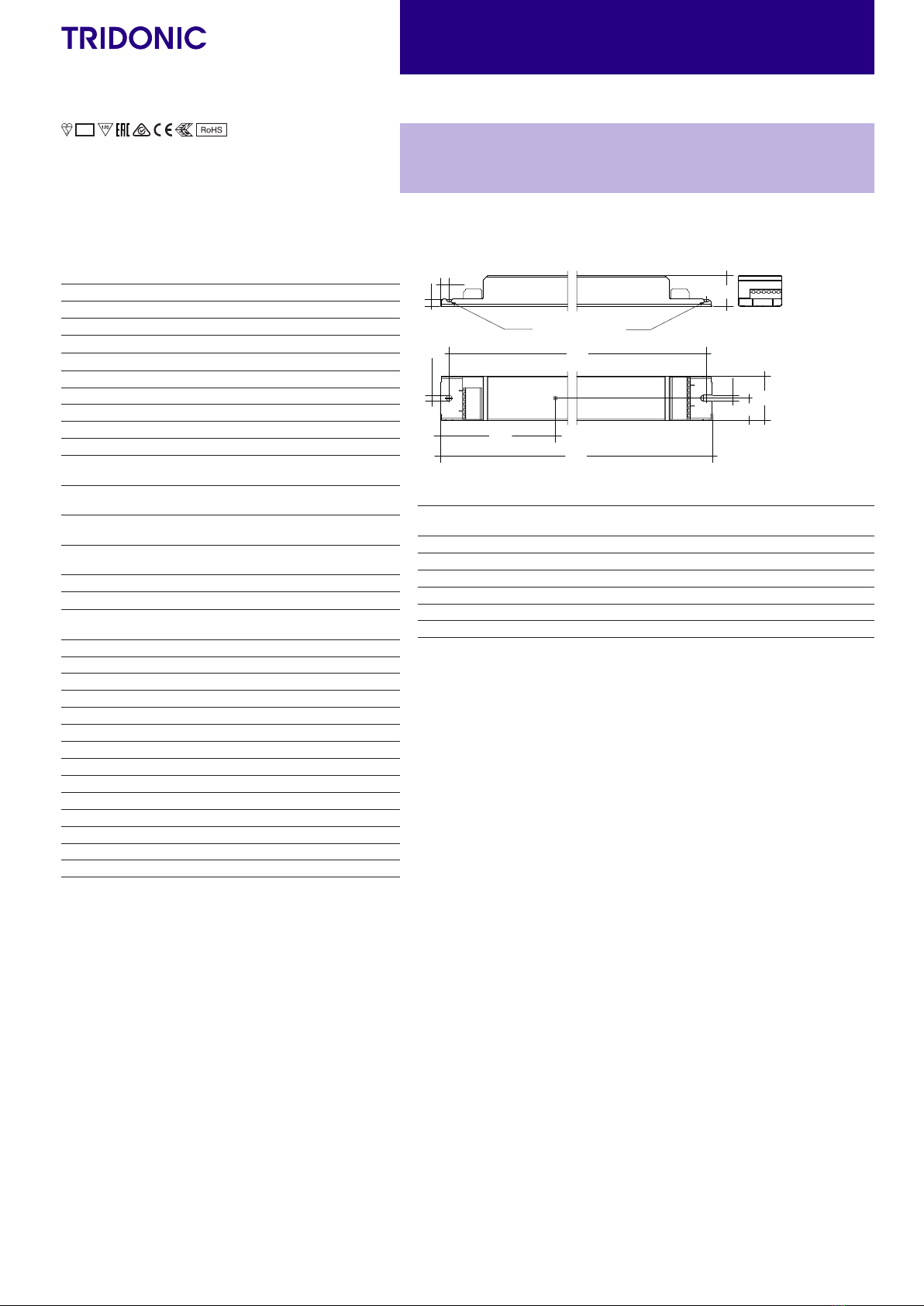
Dimensions LxBxH 360 x 30 x 21 mm
Mains voltage changeover threshold according to EN 60598-2-22
Type of protection IP20
EM powerLED BASIC FX lp 75 W
Combined emergency lighting LED Driver
15
110
tc
360
4,1
30
350
Ø4,1
6
5
21
side fixing feature
Ordering data
Type2Article
number
Rated
duration
Number
of cells
Packaging,
carton
Packaging,
pallet
Weight
per pc.
EM powerLED BASIC FX 213 lp 75W 220V 89800598 1 h 310 pc(s). 600 pc(s). 0.245 kg
EM powerLED BASIC FX 214 lp 75W 220V 89800599 1 h 410 pc(s). 600 pc(s). 0.245 kg
EM powerLED BASIC FX 215 lp 75W 220V 89800600 1 h 510 pc(s). 600 pc(s). 0.245 kg
EM powerLED BASIC FX 233 lp 75W 220V 89800601 3 h 310 pc(s). 600 pc(s). 0.245 kg
EM powerLED BASIC FX 234 lp 75W 220V 89800602 3 h 410 pc(s). 600 pc(s). 0.245 kg
EM powerLED BASIC FX 234 lp 75W 220V 89800603 3 h 510 pc(s). 600 pc(s). 0.245 kg

www.tridonic.com 3
Subject to change without notice. Information provided without guarantee.
Data sheet 12/20-EM083-11
Emergency lighting units
EM powerLED
Specific technical data
Type2Number
of battery
cells
Output
current34
Min. forward
voltage5Max. forward
voltage5Output
power
Typ. power consumption
(at 230 V, 50 Hz, full load)
Typ. current consumption
(at 230 V, 50 Hz, full load)
λ (at 230 V, 50 Hz,
full load)
I-select 2
resistor value7
Normal operation
EM powerLED BASIC FX 213 / 214 / 215 /
233 / 234 / 235 lp 75W 220V
– 80 mA 75 V 220 V 20 W 20 W 100 mA 0.85C open
– 100 mA 50 V 220 V 33 W 27 W 135 mA 0.90C 33.33 kΩ
– 150 mA 50 V 220 V 33 W 37 W 170 mA 0.95 33.33 kΩ
– 200 mA 50 V 220 V 44 W 49 W 220 mA 0.95 25.00 kΩ
– 250 mA 50 V 220 V 55 W 60 W 270 mA 0.97 20.00 kΩ
– 300 mA 50 V 220 V 66 W 71 W 320 mA 0.97 16.67 kΩ
– 350 mA 50 V 214 V 75 W 82 W 360 mA 0.98 14.29 kΩ
–400 mA 50 V 188 V 75 W 82 W 370 mA 0.98 short circuit
(0 Ω)
Emergency operation
EM powerLED BASIC FX
213 / 233 lp 75W 220V 3 see page 8 50 V 220 V 2.5 W – – all
EM powerLED BASIC FX
214 / 234 lp 75W 220V 4 see page 8 50 V 220 V 3.5 W – – all
EM powerLED BASIC FX
215 / 235 lp 75W 220V 5 see page 8 50 V 220 V 4.5 W – – all
1Depending on the selected output current.
2 EM = Emergency
3The table only lists a number of possible operating points but does not cover each single point. The output current can be set within the total value range in 1-mA-steps.
4Output current is mean value.
5 Output voltage range defined in normal operation.
6Ambient temperature range ta defined in normal operation
7Not compatible with I-select (generation 1).
www.tridonic.com 4
Subject to change without notice. Information provided without guarantee.
Data sheet 12/20-EM083-11
Emergency lighting units
EM powerLED
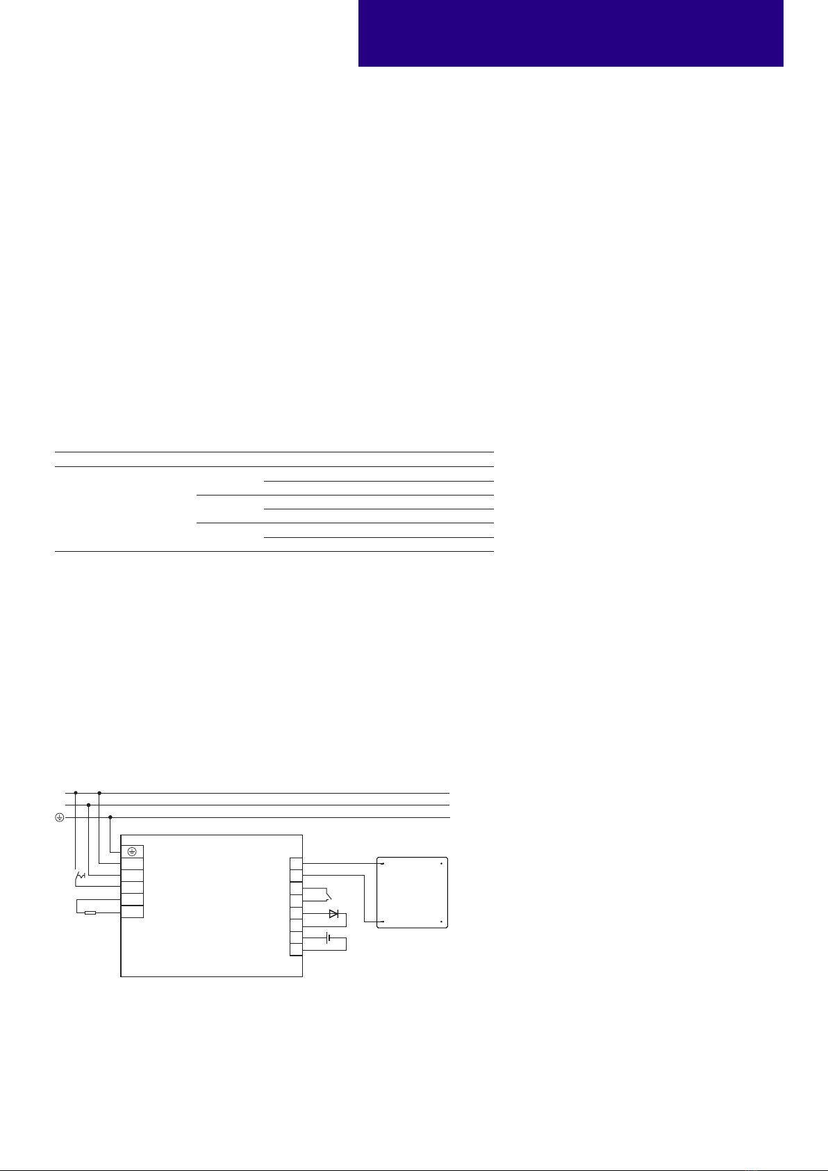
Product description
• A green LED indicates that charging current is flowing into the
battery
Status indication green LED
ACCES-
SORIES
Ordering data
Type Article number Packaging,
bag
Packaging,
carton
Weight
per pc.
LED EM green 89899605 25 pc(s). 200 pc(s). 0.011 kg
LED EM green, ultra high brightness 89899756 25 pc(s). 200 pc(s). 0.012 kg
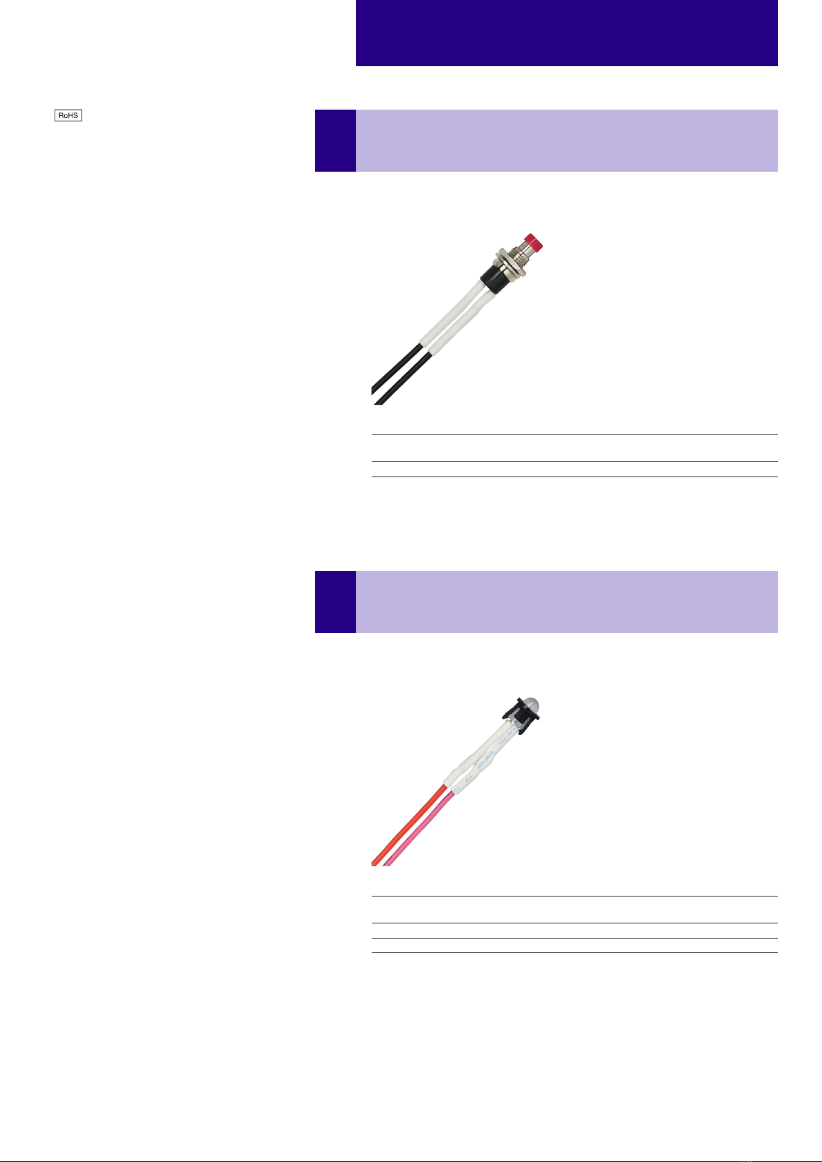
Product description
• For connection to the emergency lighting LED Driver
• For checking the device function
Test switch EM2
ACCES-
SORIES
Ordering data
Type Article number Packaging,
bag
Packaging,
carton
Weight
per pc.
Test switch EM 2 89805277 25 pc(s). 600 pc(s). 0.009 kg
I-SELECT 2 PLUG PRE / EXC
ACCES-
SORIES
3,5
xxxx
xxxx
5,54,5
7,513,5
9
Ordering data
Type Article
number Colour Marking Current Resistor
value
Packaging
bag
Weight
per pc.
I-SELECT 2 PLUG 125MA BL Blue 0125 mA 125 mA 40.00 kΩ 10 pc(s). 0.001 kg
I-SELECT 2 PLUG 150MA BL Blue 0150 mA 150 mA 33.33 kΩ 10 pc(s). 0.001 kg
I-SELECT 2 PLUG 200MA BL Blue 0200 mA 200 mA 25.00 kΩ 10 pc(s). 0.001 kg
I-SELECT 2 PLUG 225MA BL Blue 0225 mA 225 mA 22.22 kΩ 10 pc(s). 0.001 kg
I-SELECT 2 PLUG 250MA BL Blue 0250 mA 250 mA 20.00 kΩ 10 pc(s). 0.001 kg
I-SELECT 2 PLUG 275MA BL Blue 0275 mA 275 mA 18.18 kΩ 10 pc(s). 0.001 kg
I-SELECT 2 PLUG 300MA BL Blue 0300 mA 300 mA 16.67 kΩ 10 pc(s). 0.001 kg
I-SELECT 2 PLUG 325MA BL Blue 0325 mA 325 mA 15.38 kΩ 10 pc(s). 0.001 kg
I-SELECT 2 PLUG 350MA BL Blue 0350 mA 350 mA 14.29 kΩ 10 pc(s). 0.001 kg
I-SELECT 2 PLUG 375MA BL Blue 0375 mA 375 mA 13.33 kΩ 10 pc(s). 0.001 kg
I-SELECT 2 PLUG 400MA BL Blue 0400 mA 400 mA 12.50 kΩ 10 pc(s). 0.001 kg
I-SELECT 2 PLUG MAX BL Blue MAX MAX 0.00 kΩ 10 pc(s). 0.001 kg

www.tridonic.com 5
Subject to change without notice. Information provided without guarantee.
Data sheet 12/20-EM083-11
Emergency lighting units
EM powerLED
I-SELECT 2 PLUG PRE / EXC
ACCES-
SORIES
3,5
xxxx
xxxx
5,54,5
7,513,5
9
Ordering data
Type Article
number Colour Marking Current Resistor
value
Packaging
bag
Weight
per pc.
I-SELECT 2 PLUG 125MA BL Blue 0125 mA 125 mA 40.00 kΩ 10 pc(s). 0.001 kg
I-SELECT 2 PLUG 150MA BL Blue 0150 mA 150 mA 33.33 kΩ 10 pc(s). 0.001 kg
I-SELECT 2 PLUG 200MA BL Blue 0200 mA 200 mA 25.00 kΩ 10 pc(s). 0.001 kg
I-SELECT 2 PLUG 225MA BL Blue 0225 mA 225 mA 22.22 kΩ 10 pc(s). 0.001 kg
I-SELECT 2 PLUG 250MA BL Blue 0250 mA 250 mA 20.00 kΩ 10 pc(s). 0.001 kg
I-SELECT 2 PLUG 275MA BL Blue 0275 mA 275 mA 18.18 kΩ 10 pc(s). 0.001 kg
I-SELECT 2 PLUG 300MA BL Blue 0300 mA 300 mA 16.67 kΩ 10 pc(s). 0.001 kg
I-SELECT 2 PLUG 325MA BL Blue 0325 mA 325 mA 15.38 kΩ 10 pc(s). 0.001 kg
I-SELECT 2 PLUG 350MA BL Blue 0350 mA 350 mA 14.29 kΩ 10 pc(s). 0.001 kg
I-SELECT 2 PLUG 375MA BL Blue 0375 mA 375 mA 13.33 kΩ 10 pc(s). 0.001 kg
I-SELECT 2 PLUG 400MA BL Blue 0400 mA 400 mA 12.50 kΩ 10 pc(s). 0.001 kg
I-SELECT 2 PLUG MAX BL Blue MAX MAX 0.00 kΩ 10 pc(s). 0.001 kg
Product description
• Ready-for-use resistor to set output current value
• Compatible with LED Driver featuring I-select 2 interface;
not compatible with I-select (generation 1)
• Resistor is base insulated
• Resistor power 0.25 W
• Current tolerance ± 2 % to nominal current value
• Compatible with LED Driver series PRE and EXC
Example of calculation
• R [kΩ] = 5 V / I_out [mA] x 1000
• Resistor value tolerance ≤ 1 %; resistor power ≥ 0.1 W;
base insulation necessary
• When using a resistor value beyond the specified range, the
output current will automatically be set to the minimum value
(resistor value too big), respectively to the maximum value
(resistor value too small)
www.tridonic.com 6
Subject to change without notice. Information provided without guarantee.
Data sheet 12/20-EM083-11
Emergency lighting units
EM powerLED
1. Standards
• EN 61347-1
• EN 61347-2-13
• EN 61347-2-7
• EN 62384
• EN 55015
• EN 61547
• EN 61000-3-2
• EN 60068-2-29
• EN 60068-2-30
• EN 60068-2-64
• according to EN 50172
• according to EN 60598-2-22
2. Thermal data
2.1 Expected Life-time
Average life-time 50,000 hours under rated conditions with a failure rate of
less than 10 %. Average failure rate of 0.2 % per 1000 operating hours.
Wiring diagram EM powerLED BASIC FX without sensor
The connected LED module will be used for mains and emergency operation.
The mains power must be removed before changing the LED load.
Secondary switching of LEDs is not allowed and may cause damage to the
LEDs. The hot plug-in of LEDs during normal operation may result in high
current peaks.
EM powerLED BASIC
N
L+
–
+
–
S/L
I-sel 2-1
I-sel 2-2
LED
Battery
Test switch
220–240 V
L
N
50/60 Hz
–
+
Orange
Pink
Indication LED
3. Installation / Wiring
3.1 Wiring diagrams
The EM powerLED is designed for a life-time stated above under reference conditions and with a failure probability of less than 10 %.
The relation of tc to ta temperature depends also on the luminaire design.
If the measured tc temperature is approx. 5 K below tc max., ta temperature should be checked and eventually critical
components (e.g. ELCAP) measured. Detailed information on request.
Expected life-time
Type Output power ta 40 °C 50 °C 55 °C
EM powerLED BASIC FX 2xx lp
75W 220V
< 40 W tc 56 °C 66 °C 71 °C
Life-time > 100,000 h 70,000 h 50,000 h
40 – 60 W tc 60 °C 70 °C –
Life-time > 100,000 h 60,000 h –
> 60 – 75 W tc 65 °C 75 °C –
Life-time > 100,000 h 50,000 h –

www.tridonic.com 7
Subject to change without notice. Information provided without guarantee.
Data sheet 12/20-EM083-11
Emergency lighting units
EM powerLED
Maximum lead length
LED 3 m
status indication LED 1 m
batteries 1 m
3.4 Wiring guidelines
• The output to the LED is DC but has high frequency content, which should be
considered for good EMC compliance.
• LED leads should be separated from the mains connections and wiring for
good EMC performance.
• Maximum lead length on the LED terminals is 3 m. For a good EMC
performance keep the LED wiring as short as possible.
• The secondary wires (LED module) should be routed in parallel to ensure
good EMC performance.
• Maximum lead length for the Test switch and Indicator LED connection is 1 m.
The test switch and Indicator LED wiring should be separated from the LED
leads to prevent noise coupling.
• Battery leads are specified with 0.5 mm cross section and a length of 1.3 m.
• To avoid the damage of the control gear, the wiring must be protected against
short circuits to earth (sharp edged metal parts, metal cable clips, louver, etc.).
To ensure that a luminaire containing LED emergency units complies with
EN 55015 for radio frequency conducted interference in both normal and emer-
gency mode it is essential to follow good practice in the wiring layout.
Within the luminaire the switched and unswitched 50 Hz supply wiring must be
routed as short as possible and be kept as far away as possible from the LED
leads.Through wiring may affect the emc performance of the luminaire.
The length of LED leads must not be exceeded.
The output current depends on the forward voltage and the tolerance of the
LED modules.
4. Mechanical data
4.1 Housing properties
4.2 Mechanichal data accessories
LED status indicator
• Green
• Mounting hole 6.5 mm diameter, 1 – 1.6 mm thickness
• Lead length 0.8 m
• Insulation rating: 90 °C
Test switch
• Mounting hole 7.0 mm diameter
• Lead length 0.55 m
Battery leads
• Quantity: 1 red and 1 black
• Length: 1.3 m
• Wire type: 0.5 mm2solid conductor
• Insulation rating: 90 °C
Battery end termination
Push on 4.8 mm receptacle to suit battery spade fitted with insulating cover
or plug connection.
Module end termination
8.0 mm stripped insulation
Two-piece batteries are supplied with a 200 mm lead with 4.8 mm receptacle
at each end and insulating covers to connect the separate sticks together.
• Low-profile metal casing with white cover
• Type of protection IP 20
LED module/LED Driver/supply
8 – 9 mm
wire preparation:
0.5 – 1.5 mm²
3.2 Wiring type and cross section
Solid wire with a cross section of 0.5 – 1.5 mm². Strip 8 – 9 mm of insulation
from the cables to ensure perfect operation of terminals.
3.3 Loose wiring
Loosen wire through twisting
and pulling or using a Ø1 mm
release tool

www.tridonic.com 8
Subject to change without notice. Information provided without guarantee.
Data sheet 12/20-EM083-11
Emergency lighting units
EM powerLED
5. Electrical values
Automatic circuit breaker type C10 C13 C16 C20 B10 B13 B16 B20 Inrush current
Installation Ø1.5 mm21.5 mm22.5 mm22.5 mm21.5 mm21.5 mm22.5 mm22.5 mm2Imax time
EM powerLED BASIC FX 2xx lp 75W 220V 12 18 24 28 6 9 12 14 25.8 A 280 µs
5.1 Maximum loading of automatic circuit breakers
Calculation uses typical values from ABB series S200 as a reference.
Actual values may differ due to used circuit breaker types and installation environment.
Insulate the battery, LED, test switch and indicator LED in the luminaire according to the U-OUT rating of the LED Driver.
5.2 Insulation matrix
Mains Switched Live Battery, LED, Test
switch, Indicator LED I-SELECT 2
Mains – • • • •
Switched Live • – • • •
Battery, LED, Test
switch, Indicator LED • • • • –• •
I-SELECT 2 • • • • –
• Represents basic insulation
• • Represents double or reinforced insulation

www.tridonic.com 9
Subject to change without notice. Information provided without guarantee.
Data sheet 12/20-EM083-11
Emergency lighting units
EM powerLED
5.3 Typ. LED current/voltage characteristics
The LED current in emergency mode is automatically adjusted by the EM powerLED module based on the total forward voltage of the LED modules
connected and the associated battery. The start of the LED in emergency mode does not result in a current peak.
EM powerLED BASIC FX 213 / 233 lp 75W 220V
Article number: 89800598 / 89800601
3.6 V battery voltage
850 – 960 mA battery discharge current (tolerance)
EM powerLED BASIC FX 214 / 234 lp 75W 220V
Article number: 89800599 / 89800602
4.8 V battery voltage
850 – 960 mA battery discharge current (tolerance)
LED current [mA]
VLED [V] VLED [V]
LED current [mA]
50 9070 110 150 210130 170 190
10
20
30
0
70
60
40
50
80
50 9070 110 150 210130 170 190
10
20
30
0
50
40
60
EM powerLED BASIC FX 215 / 235 lp 75W 220V
Article number: 89800600 / 89800603
6.0 V battery voltage
850 – 960 mA battery discharge current (tolerance)
50 9070 110 150 210130 170 190
10
20
30
0
80
90
70
60
40
50
100
LED current [mA]
LED current at nominal battery voltage and
min. battery discharge current
LED current at nominal battery voltage and
max. battery discharge current
VLED [V]

www.tridonic.com 10
Subject to change without notice. Information provided without guarantee.
Data sheet 12/20-EM083-11
Emergency lighting units
EM powerLED
0
5
20 70 80 9050 6030 40
100
20
15
10
25
30
35
40
Load [%]
THD [%]
40
70
50
60
80
20 50 60 70 80 9030 40
100
100
90
Load [%]
Eiciency [%]
0
50
100
150
200
0150 250200 300 350 40050 100 450
250
Output current [mA]
Output voltage [V]
0,4
0,5
0,6
0,7
0,8
0,9
1,0
20 50 60 70 80 9030 40
100
Load [%]
Power factor
100 % load corresponds to the max. output power (full load) according to the
table on page 2.
100 mA
400 mA
250 mA
5.7 THD vs load
THD without harmonic < 5 mA or 0.6 % of the input current:
5.5 Efficiency vs load
5.6 Power factor vs load
5.4 Operating window
Operating window 100 %
Make sure that the LED Driver is operated within the given window under all
operating conditions. Coming below the specified minimum output voltage of
the LED Driver may cause the device to shut-down.
www.tridonic.com 11
Subject to change without notice. Information provided without guarantee.
Data sheet 12/20-EM083-11
Emergency lighting units
EM powerLED
7. Functions
6. Emergency output factor EOFi
Please note that the resistor values for I-select 2 are not compatible
with I-select (generation 1). Installation of an incorrect resistor may
cause irreparable damage to the LED module(s).
Resistors for the main output current values can be ordered from Tridonic
(see accessories).
Option 2: ready2mains
Adjustment is done by the ready2mains Programmer and the corresponding
configuration software (see ready2mains documentation).
Current adjustment can only be done five times over ready2mains.
To program the EM powerLED a connected load is necessary that is
within the operating window of the EM powerLED.
The priority for current adjustment methods is I-select 2 followed by
ready2mains (lowest priority).
7.1 Function: adjustable current
The output current of the EM powerLED can be adjusted in a certain range.
For adjustment there are two options available.
Option 1: I-select 2
By inserting a suitable resistor or third party resistor into the I-select 2
interface, the current value can be adjusted. The relationship between
output current and resistor value can be found in the chapter “Accessories
I-SELECT 2 Plugs”.
7.2 Short-circuit behaviour
In case of a short-circuit at the LED output the LED output is switched off. After
restart of the EM powerLED the output will be activated again. The restart
can either be done via mains reset or via interface ready2mains.
7.3 No-load operation
The EM powerLED will not be damaged in no-load operation. The output will be
deactivated and is therefore free of voltage. If a LED load is connected the
device has to be restarted before the output will be activated again.
7.4 Overload protection
If the output voltage range is exceeded the EM powerLED turns off the LED
output. After restart of the EM powerLED the output will be activated again.
The restart can be done via mains reset.
7.5 Overtemperature protection
The EM powerLED is protected against temporary thermal overheating. If
the temperature limit is exceeded the output current of the LED module(s) is
reduced. The temperature protection is activated approx. +5 °C above tc max
(see page 2).
7.6 Forward voltage out of range
If the forward voltage is out of range the unit switches to shut down mode.
After elimination of the short circuit a mains reset (SL off/on) is necessary.
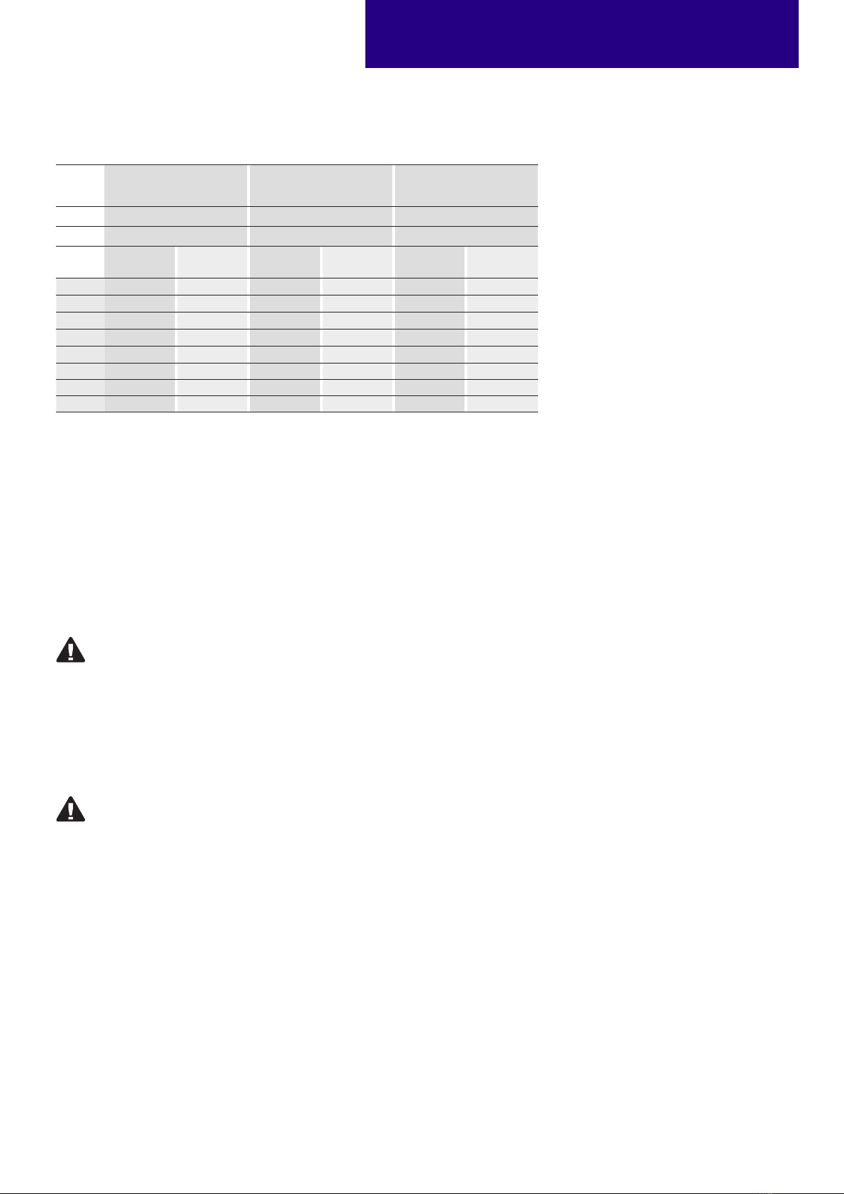
EM powerLED BASIC
Type EM powerLED BASIC FX
213/233 lp 75W 220V
EM powerLED BASIC FX
214/234 lp 75W 220V
EM powerLED BASIC FX
215/235 lp 75W 220V
Article no. 89800598 / 89800601 89800599 / 89800602 89800600 / 89800603
Cells 3 cells 4 cells 5 cells
Output
current Min. LED load Max. LED load Min. LED load Max. LED load Min. LED load Max. LED load
mA
mA
mA
mA
mA
mA
mA
mA

www.tridonic.com 12
Subject to change without notice. Information provided without guarantee.
Data sheet 12/20-EM083-11
Emergency lighting units
EM powerLED
EM powerLED BASIC, 1 / 3 h
Type
EM powerLED
BASIC FX
213 lp 75W 220V
EM powerLED
BASIC FX
233 lp 75W 220V
EM powerLED
BASIC FX
214 lp 75W 220V
EM powerLED
BASIC FX
234 lp 75W 220V
EM powerLED
BASIC FX
215 lp 75W 220V
EM powerLED
BASIC FX
235 lp 75W 220V
Article no. 89800598 89800601 89800599 89800602 89800600 89800603
Cells 3 cells 3 cells 4 cells 4 cells 5 cells 5 cells
Duration 1 h 3 h 1 h 3 h 1 h 3 h
Technology
and capacity
Design Number
of cells
Type Article no. Assignable batteries
NiCd 4 Ah
D cells
stick 1 x 3 Accu-NiCd 3A 55 •
stick 1 x 4 Accu-NiCd 4A 55 •
stick 1 x 5 Accu-NiCd 5A 55 •
side by side 3 x 1 Accu-NiCd 3B 55 •
side by side 4 x 1 Accu-NiCd 4B 55 •
stick + stick 2 + 2 Accu-NiCd 4C 55 •
stick + stick 3 + 2 Accu-NiCd 5C 55 •
remote box 1 x 3 Pack-NiCd 3D CON •
remote box 1 x 4 Pack-NiCd 4D CON •
remote box 1 x 5 Pack-NiCd 5D CON •
NiMH 2.2 Ah
Cs cells
stick 1 x 3 Accu-NiMH 3A •
stick 1 x 4 Accu-NiMH 4A •
stick 1 x 5 Accu-NiMH 5A •
side by side 5 x 1 Accu-NiMH 5B •
remote box 1 x 3 Pack-NiMH 2.2Ah 3 CON •
remote box 1 x 4 Pack-NiMH 2.2Ah 4 CON •
NiMH 4 Ah
LA cells
stick 1 x 3 Accu-NiMH 4Ah 3A CON •
stick 1 x 4 Accu-NiMH 4Ah 4A CON •
stick + stick 2 + 2 Accu-NiMH 4Ah 4C CON •
stick + stick 2 + 3 Accu-NiMH 4Ah 5C CON •
remote box 1 x 3 Pack-NiMH 4Ah 3 CON •
remote box 1 x 4 Pack-NiMH 4Ah 4 CON •
8.1 Battery selection
8. Battery data
EM powerLED BASIC, 1 / 3 h
Type EM powerLED BASIC FX
213 / 214 / 215 lp 75W 220V
EM powerLED BASIC FX
233 / 234 / 235 lp 75W 220V
Article no. 89800598 / 89800596 / 89800600 89800601 / 89800602 / 89800603
Cells 3 / 4 / 5 cells 3 / 4 / 5 cells
Duration 1 h 3 h
Battery charge
time
Initial charge 24 h
Fast recharge 24 h
Trickle charge continuously
Charging current
Initial charge 105 mA 195 mA
Fast recharge 105 mA 195 mA
Trickle charge 70 mA 105 mA
Discharge current 850 – 960 mA 850 – 960 mA
8.2 Battery charge / discharge data

www.tridonic.com 13
Subject to change without notice. Information provided without guarantee.
Data sheet 12/20-EM083-11
Emergency lighting units
EM powerLED
8.7 Batteries
Connection method: 4.8 x 0.5 mm spade tag welded to end of cell
For stick packs this connection is accessible after the battery caps have been
fitted.
To inhibit inverter operation disconnect the batteries by removing the
connector from the battery spade tag.
For further information refer to corresponding battery datasheet.
8.8 Storage, installation and commissioning
Relevant information about storage conditions, installation and commissioning
are provided in the battery datasheets.
8.3 Accu-NiCd
4.2 / 4.5 Ah
International designation KRMU 33/62
Battery voltage/cell 1.2 V
Cell type D
Case temperature range
to ensure 4 years design life +5 °C to +55 °C
Max. short term temperature (reduced life-time) 70 °C
Max. number discharge cycles 12 cycles per year plus
4 cycles during
comissioning
Max. storage time 12 months
8.4 Accu-NiMH
2.2 Ah
International designation HRMU 23/43
Battery voltage/cell 1.2 V
Cell type Cs
Case temperature range
to ensure 4 years design life +5 °C to +50 °C
Max. short term temperature (reduced life-time) 70 °C
Max. number discharge cycles 4 cycles per year plus
30 cycles during
comissioning
Max. storage time 12 months
4.0 Ah
International designation HRMU 19/90
Battery voltage/cell 1.2 V
Cell type LA
Case temperature range
to ensure 4 years design life +5 °C to +45 °C
Max. short term temperature (reduced life-time) 70 °C
Max. number discharge cycles 4 cycles per year plus
30 cycles during
comissioning
Max. storage time 12 months
8.5 Accupack-NiCd
4.5 Ah
Battery voltage/cell 1.2 V
Cell type D
Ambient temperature range
to ensure 4 years design life +5 °C to +40 °C
tc point +45 °C
Max. short term temperature (reduced life-time) 70 °C
Max. number discharge cycles 4 cycles per year plus
4 cycles during
comissioning
Max. storage time 6 months
8.6 Accupack-NiMH
2.2 Ah
Battery voltage/cell 1.2 V
Cell type Cs
Ambient temperature range
to ensure 4 years design life +5 °C to +35 °C
tc point +40 °C
Max. short term temperature (reduced life-time) 70 °C
Max. number discharge cycles 4 cycles per year plus
4 cycles during
comissioning
Max. storage time 12 months
4.0 Ah
Battery voltage/cell 1.2 V
Cell type LAL
Ambient temperature range
to ensure 4 years design life +5 °C to +35 °C
tc point +40 °C
Max. short term temperature (reduced life-time) 70 °C
Max. number discharge cycles 4 cycles per year plus
4 cycles during
comissioning
Max. storage time 12 months
For a higher battery temperature rating for NiMH 4 Ah refer to the
EM converterLED xx MH/LiFePO4 product range.

www.tridonic.com 14
Subject to change without notice. Information provided without guarantee.
Data sheet 12/20-EM083-11
Emergency lighting units
EM powerLED
9. Miscellaneous
9.1 Maximum number of switching cycles
All LED Drivers are tested with 50,000 switching cycles.
The actually achieved number of switching cycles is significantly higher.
9.2 Insulation and electric strength testing of luminaires
Electronic devices can be damaged by high voltage. This has to be considered
during the routine testing of the luminaires in production.
According to IEC 60598-1 Annex Q (informative only!) or ENEC 303-Annex A,
each luminaire should be submitted to an insulation test with 500V DC for one
second. This test voltage should be connected between the interconnected
phase and neutral terminals and the earth terminal.
The insulation resistance must be at least 2 MΩ.
As an alternative, IEC 60598-1 Annex Q describes a test of the electrical
strength with 1500 V AC (or 1.414 x 1500 V DC). To avoid damage to the electronic
devices this test must not be conducted.
9.3 Conditions of use and storage
Humidity: 5 % up to max. 85 %,
not condensed
(max. 56 days/year at 85 %)
Storage temperature: -40 °C up to max. +80 °C
The devices have to be acclimatised to the specified temperature range (ta)
before they can be operated.
9.4 Additional information
Additional technical information at www.tridonic.com →Technical Data
Guarantee conditions at www.tridonic.com →Services
Life-time declarations are informative and represent no warranty claim.
No warranty if device was opened.
This manual suits for next models
11
Table of contents
Other Tridonic DC Drive manuals


Popular DC Drive manuals by other brands

KEBCO
KEBCO COMBIVERT F5 Series instruction manual

Black Box
Black Box ME785A manual

Masterflex
Masterflex L/S 07528-40 operating manual

Baoding Longer Precision Pump
Baoding Longer Precision Pump WT3000-1FB operating manual

hpmont
hpmont HD30 Series manual

Anaheim Automation
Anaheim Automation DPD75601 user guide


Allen-Bradley
Allen-Bradley CX300 troubleshooting guide

Festo Pneumatic
Festo Pneumatic DRQ-20-PPVJ-A operating instructions

Pfeiffer Vacuum
Pfeiffer Vacuum TM 700 operating instructions

Danfoss
Danfoss VLT 5000 Series instruction manual

Conner
Conner 800 MB Travan installation manual

Danfoss
Danfoss VLT FC 360 Design guide