Tridonic LCO EXC3 User manual

LED-Driver
LCO EXC3/ADV3 OTD
Product Manual

Manual LCO EXC3/ADV3 OTD | 03-2020 | 1.2 | en
Table of Contents
c2 / 63
1. Validity 4
1.1. Copyright . . . . . . . . . . . . . . . . . . . . . . . . . . . . . . . . . . . . . . . . . . . . . . . . . . . . . . . . . . . . . . . . . . . . . . . . . . . . . . . . . . . . . . . . . . . . . . . . . . . . . . . . . . . . . . . . . 4
1.2. Imprint . . . . . . . . . . . . . . . . . . . . . . . . . . . . . . . . . . . . . . . . . . . . . . . . . . . . . . . . . . . . . . . . . . . . . . . . . . . . . . . . . . . . . . . . . . . . . . . . . . . . . . . . . . . . . . . . . . . 4
2. General safety instructions 5
2.1. Intended use . . . . . . . . . . . . . . . . . . . . . . . . . . . . . . . . . . . . . . . . . . . . . . . . . . . . . . . . . . . . . . . . . . . . . . . . . . . . . . . . . . . . . . . . . . . . . . . . . . . . . . . . . . . . . . 5
2.2. Dangers associated with the operation of the system . . . . . . . . . . . . . . . . . . . . . . . . . . . . . . . . . . . . . . . . . . . . . . . . . . . . . . . . . . . . . . . . . . . . . . . 5
2.3. Environment . . . . . . . . . . . . . . . . . . . . . . . . . . . . . . . . . . . . . . . . . . . . . . . . . . . . . . . . . . . . . . . . . . . . . . . . . . . . . . . . . . . . . . . . . . . . . . . . . . . . . . . . . . . . . 5
2.4. Additional instructions . . . . . . . . . . . . . . . . . . . . . . . . . . . . . . . . . . . . . . . . . . . . . . . . . . . . . . . . . . . . . . . . . . . . . . . . . . . . . . . . . . . . . . . . . . . . . . . . . . . . 6
3. Description and key features 7
3.1. Description of key features . . . . . . . . . . . . . . . . . . . . . . . . . . . . . . . . . . . . . . . . . . . . . . . . . . . . . . . . . . . . . . . . . . . . . . . . . . . . . . . . . . . . . . . . . . . . . . . . 7
3.2. Main values and functions . . . . . . . . . . . . . . . . . . . . . . . . . . . . . . . . . . . . . . . . . . . . . . . . . . . . . . . . . . . . . . . . . . . . . . . . . . . . . . . . . . . . . . . . . . . . . . . . 8
3.3. Housing variants . . . . . . . . . . . . . . . . . . . . . . . . . . . . . . . . . . . . . . . . . . . . . . . . . . . . . . . . . . . . . . . . . . . . . . . . . . . . . . . . . . . . . . . . . . . . . . . . . . . . . . . . 10
3.4. Adjustable output current EXC3 . . . . . . . . . . . . . . . . . . . . . . . . . . . . . . . . . . . . . . . . . . . . . . . . . . . . . . . . . . . . . . . . . . . . . . . . . . . . . . . . . . . . . . . . . . 12
3.5. Adjustable output current ADV3 . . . . . . . . . . . . . . . . . . . . . . . . . . . . . . . . . . . . . . . . . . . . . . . . . . . . . . . . . . . . . . . . . . . . . . . . . . . . . . . . . . . . . . . . . . 12
4. Compatibility between LED module and LED Driver 13
4.1. Comparison of data sheet values with a 5-point guideline . . . . . . . . . . . . . . . . . . . . . . . . . . . . . . . . . . . . . . . . . . . . . . . . . . . . . . . . . . . . . . . . . . 13
4.2. Practical tests . . . . . . . . . . . . . . . . . . . . . . . . . . . . . . . . . . . . . . . . . . . . . . . . . . . . . . . . . . . . . . . . . . . . . . . . . . . . . . . . . . . . . . . . . . . . . . . . . . . . . . . . . . . 15
4.3. Application of the 5-point guideline . . . . . . . . . . . . . . . . . . . . . . . . . . . . . . . . . . . . . . . . . . . . . . . . . . . . . . . . . . . . . . . . . . . . . . . . . . . . . . . . . . . . . . 16
5. Installation notes 22
5.1. Safety information . . . . . . . . . . . . . . . . . . . . . . . . . . . . . . . . . . . . . . . . . . . . . . . . . . . . . . . . . . . . . . . . . . . . . . . . . . . . . . . . . . . . . . . . . . . . . . . . . . . . . . . 22
5.2. Function of the earth terminal . . . . . . . . . . . . . . . . . . . . . . . . . . . . . . . . . . . . . . . . . . . . . . . . . . . . . . . . . . . . . . . . . . . . . . . . . . . . . . . . . . . . . . . . . . . . 23
5.3. Routing the wires . . . . . . . . . . . . . . . . . . . . . . . . . . . . . . . . . . . . . . . . . . . . . . . . . . . . . . . . . . . . . . . . . . . . . . . . . . . . . . . . . . . . . . . . . . . . . . . . . . . . . . . . 25
5.4. External fuse for DC operation . . . . . . . . . . . . . . . . . . . . . . . . . . . . . . . . . . . . . . . . . . . . . . . . . . . . . . . . . . . . . . . . . . . . . . . . . . . . . . . . . . . . . . . . . . . 26
5.5. Maximum loading of circuit breakers . . . . . . . . . . . . . . . . . . . . . . . . . . . . . . . . . . . . . . . . . . . . . . . . . . . . . . . . . . . . . . . . . . . . . . . . . . . . . . . . . . . . . 27
6. Functions and interfaces 32
6.1. IVG Plus . . . . . . . . . . . . . . . . . . . . . . . . . . . . . . . . . . . . . . . . . . . . . . . . . . . . . . . . . . . . . . . . . . . . . . . . . . . . . . . . . . . . . . . . . . . . . . . . . . . . . . . . . . . . . . . . . 32
6.2. eCLO . . . . . . . . . . . . . . . . . . . . . . . . . . . . . . . . . . . . . . . . . . . . . . . . . . . . . . . . . . . . . . . . . . . . . . . . . . . . . . . . . . . . . . . . . . . . . . . . . . . . . . . . . . . . . . . . . . . 34
6.3. inputDIM . . . . . . . . . . . . . . . . . . . . . . . . . . . . . . . . . . . . . . . . . . . . . . . . . . . . . . . . . . . . . . . . . . . . . . . . . . . . . . . . . . . . . . . . . . . . . . . . . . . . . . . . . . . . . . . . 36
6.4. External temperature management (only EXC3) . . . . . . . . . . . . . . . . . . . . . . . . . . . . . . . . . . . . . . . . . . . . . . . . . . . . . . . . . . . . . . . . . . . . . . . . . . 38
6.5. chronoSTEP V2 . . . . . . . . . . . . . . . . . . . . . . . . . . . . . . . . . . . . . . . . . . . . . . . . . . . . . . . . . . . . . . . . . . . . . . . . . . . . . . . . . . . . . . . . . . . . . . . . . . . . . . . . . 40
6.6. U6Me2 . . . . . . . . . . . . . . . . . . . . . . . . . . . . . . . . . . . . . . . . . . . . . . . . . . . . . . . . . . . . . . . . . . . . . . . . . . . . . . . . . . . . . . . . . . . . . . . . . . . . . . . . . . . . . . . . . . 42
6.7. corridorFUNCTION V2 (only EXC3) . . . . . . . . . . . . . . . . . . . . . . . . . . . . . . . . . . . . . . . . . . . . . . . . . . . . . . . . . . . . . . . . . . . . . . . . . . . . . . . . . . . . . . . 43
6.8. DSI (only EXC3) . . . . . . . . . . . . . . . . . . . . . . . . . . . . . . . . . . . . . . . . . . . . . . . . . . . . . . . . . . . . . . . . . . . . . . . . . . . . . . . . . . . . . . . . . . . . . . . . . . . . . . . . . 48
6.9. switchDIM (only EXC3) . . . . . . . . . . . . . . . . . . . . . . . . . . . . . . . . . . . . . . . . . . . . . . . . . . . . . . . . . . . . . . . . . . . . . . . . . . . . . . . . . . . . . . . . . . . . . . . . . . 49
6.10. Power-up Fading (only EXC3) . . . . . . . . . . . . . . . . . . . . . . . . . . . . . . . . . . . . . . . . . . . . . . . . . . . . . . . . . . . . . . . . . . . . . . . . . . . . . . . . . . . . . . . . . . . 53
6.11. DALI (only EXC3) . . . . . . . . . . . . . . . . . . . . . . . . . . . . . . . . . . . . . . . . . . . . . . . . . . . . . . . . . . . . . . . . . . . . . . . . . . . . . . . . . . . . . . . . . . . . . . . . . . . . . . . 54

Manual LCO EXC3/ADV3 OTD | 03-2020 | 1.2 | en
Table of Contents
c3 / 63
...
6.12. ready2mains . . . . . . . . . . . . . . . . . . . . . . . . . . . . . . . . . . . . . . . . . . . . . . . . . . . . . . . . . . . . . . . . . . . . . . . . . . . . . . . . . . . . . . . . . . . . . . . . . . . . . . . . . . . 56
6.13. DC recognition . . . . . . . . . . . . . . . . . . . . . . . . . . . . . . . . . . . . . . . . . . . . . . . . . . . . . . . . . . . . . . . . . . . . . . . . . . . . . . . . . . . . . . . . . . . . . . . . . . . . . . . . . 57
6.14. Dimming on DC (only EXC3) . . . . . . . . . . . . . . . . . . . . . . . . . . . . . . . . . . . . . . . . . . . . . . . . . . . . . . . . . . . . . . . . . . . . . . . . . . . . . . . . . . . . . . . . . . . . 58
6.15. Intelligent Temperature Guard . . . . . . . . . . . . . . . . . . . . . . . . . . . . . . . . . . . . . . . . . . . . . . . . . . . . . . . . . . . . . . . . . . . . . . . . . . . . . . . . . . . . . . . . . . 59
6.16. Surge Burst protection . . . . . . . . . . . . . . . . . . . . . . . . . . . . . . . . . . . . . . . . . . . . . . . . . . . . . . . . . . . . . . . . . . . . . . . . . . . . . . . . . . . . . . . . . . . . . . . . . . 61
7. Reference list 62
7.1. Additional information . . . . . . . . . . . . . . . . . . . . . . . . . . . . . . . . . . . . . . . . . . . . . . . . . . . . . . . . . . . . . . . . . . . . . . . . . . . . . . . . . . . . . . . . . . . . . . . . . . . 62
7.2. Downloads . . . . . . . . . . . . . . . . . . . . . . . . . . . . . . . . . . . . . . . . . . . . . . . . . . . . . . . . . . . . . . . . . . . . . . . . . . . . . . . . . . . . . . . . . . . . . . . . . . . . . . . . . . . . . . 62
7.3. Technical data . . . . . . . . . . . . . . . . . . . . . . . . . . . . . . . . . . . . . . . . . . . . . . . . . . . . . . . . . . . . . . . . . . . . . . . . . . . . . . . . . . . . . . . . . . . . . . . . . . . . . . . . . . 63

Manual LCO EXC3/ADV3 OTD | 03-2020 | 1.2 | en
Scope of documentation
c4 / 63
These operating instructions are valid for LED Drivers of the L series.CO NFC C EXC3 and LCO NFC C ADV3
TRIDONIC GmbH & Co KG is constantly striving to develop all its products. This means that there may be changes in form, equipment
and technology.
Claims cannot therefore be made on the basis of information, diagrams or descriptions in these instructions.
The latest version of these operating instructions is available on our home page at
http://www.tridonic.com/com/en/operating-instructions.asp
Copyright
This documentation may not be changed, expanded, copied or passed to third parties without the prior written agreement of
TRIDONIC GmbH & Co KG.
Imprint
Tridonic GmbH & Co KG
Färbergasse 15
6851 Dornbirn
Austria
T +43 5572 395-0
F +43 5572 20176
www.tridonic.com
...

Manual LCO EXC3/ADV3 OTD | 03-2020 | 1.2 | en
General safety instructions
c5 / 63
The instructions in this section have been compiled to ensure that operators and users of LED Drivers of the LCO NFC C EXC3 and
series from Tridonic are able to detect potential risks on time and take the necessary preventative measures.LCO NFC C ADV3
The operator must ensure that all users fully understand these instructions and follow them. This device may only be installed and
configured by suitably qualified personnel.
Intended use
Proper use
Operation of LED light modules. The device may only be used for this intended purpose.
Improper use
Outdoor use. Extensions and modifications to the product.
Dangers associated with the operation of the system
Environment
½WARNING!
Improper use could result in injury, malfunction or damage to property.
It must be ensured that the operator informs every user of existing hazards.
½DANGER!
Danger of electrocution
Disconnect the power of the entire lighting system before working on the lighting system!
½DANGER!
Not to be used in corrosive or explosive environments.
½CAUTION!
Risk of damage caused by humidity and condensation
Use use the control device only in dry rooms and protect it against humidity!_
Prior to commissioning the system, wait until the control device is at room temperature and completely dry!_

Manual LCO EXC3/ADV3 OTD | 03-2020 | 1.2 | en
General safety instructions
c6 / 63
Additional instructions
...
½CAUTION!
Electromagnetic compatibility (EMC)
Although the device meets the stringent requirements of the appropriate directives and standards on electromagnetic
compatibility, it could potentially interfere with other devices under certain circumstances!

Manual LCO EXC3/ADV3 OTD | 03-2020 | 1.2 | en
Description and key features
c7 / 63
Description of key features
LCO NFC C EXC3 and LCO NFC C ADV3 is a specially designed portfolio for outdoor and industrial applications. It has been optimised
to meet the hardest requirements in outdoor LED applications.
...
Special design:
The offer a safe and reliable solution under difficult weather and electricalLCO NFC C EXC3 and LCO NFC C ADV3
circumstances (e.g. street and roadlight, tunnel, carpark)
_
Lifetime:
Excellent lifetime thanks to special design
_
Safety:
Up to 10 kV surge/burst protection
_
Thermomanagement:
t up to 70 °C with 65,000 hours lifetime
a
_
State-of-the-art dimming technology:
Stepless dimming from 100 to 5 %
_
Diversity of functions:_
EXC3: NFC, U6Me2, ready2mains, DALI, ETM, one4all_
ADV3: NFC, U6Me2, ready2mains_

Manual LCO EXC3/ADV3 OTD | 03-2020 | 1.2 | en
Main values and functions
c8 / 63
Main values and functions
Dimming
Portfolio Description
Dimmable
Dimming method Amplitude dimming
Dimming range 100 to 5 %
Dimming curve Logarithmic dimming curve (standard)
Switching to linear dimming curve via masterCONFIGURATOR is possible.
Dimming interfaces EXC3 DALI V2-DT6, DSI, corridorFUNCTION V2, switchDIM, chronoSTEP V2, inputDIM
Dimming interfaces ADV3 chronoSTEP V2, inputDIM
Functions
Portfolio Description
Intelligent Voltage Guard
Intelligent Temperature Guard
Power-up Fading
DC Operation DC level adjustable
supporting EN 50172
eCLO
Configuration Interfaces EXC3 NFC, DALI V2-DT6, ready2mains, U6Me2
Configuration Interfaces ADV3 NFC, ready2mains
Output current
Portfolio Description
Adjustable output current
EXC3 adjustable via... NFC, DALI V2-DT6, ready2mains
ADV3 adjustable via... NFC, ready2mains
Step size 1 mA
Tolerance Further information can be found in the data sheet (see ).Reference list, p. 62

Manual LCO EXC3/ADV3 OTD | 03-2020 | 1.2 | en
Main values and functions
c9 / 63
Technical data
Portfolio Description
Rated supply voltage 220-240 V
Standby losses < 0.16 W
...
Manual LCO EXC3/ADV3 OTD | 03-2020 | 1.2 | en
Housing variants
c10 / 63
Housing variants
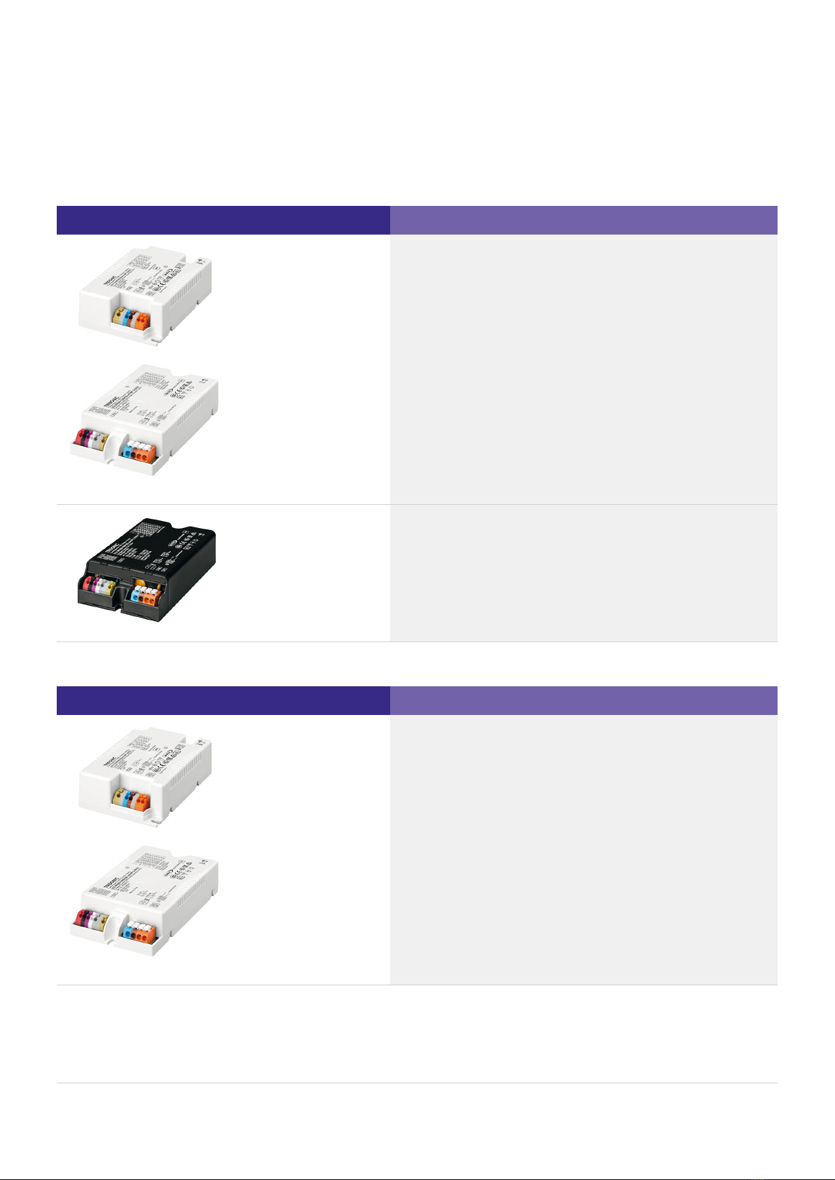
LCO one4all NFC C EXC3 is available in the following housing variants:
Image Description
Housing variant compact
Housing variant compact potted
LCO NFC C ADV3 is available in the following housing variants:
Image Description
Housing variant compact
Compact shape for installation inside the luminaire casing
(in-built)
Typical area of application: Road, street, industry
_
Compact shape for installation inside the luminaire casing
(in-built)
_
Typical area of application: Road, street, industry_
Compact shape for installation inside the luminaire casing
(in-built)
_
Typical area of application: Road, street, industry
_
Manual LCO EXC3/ADV3 OTD | 03-2020 | 1.2 | en
Housing variants
c11 / 63
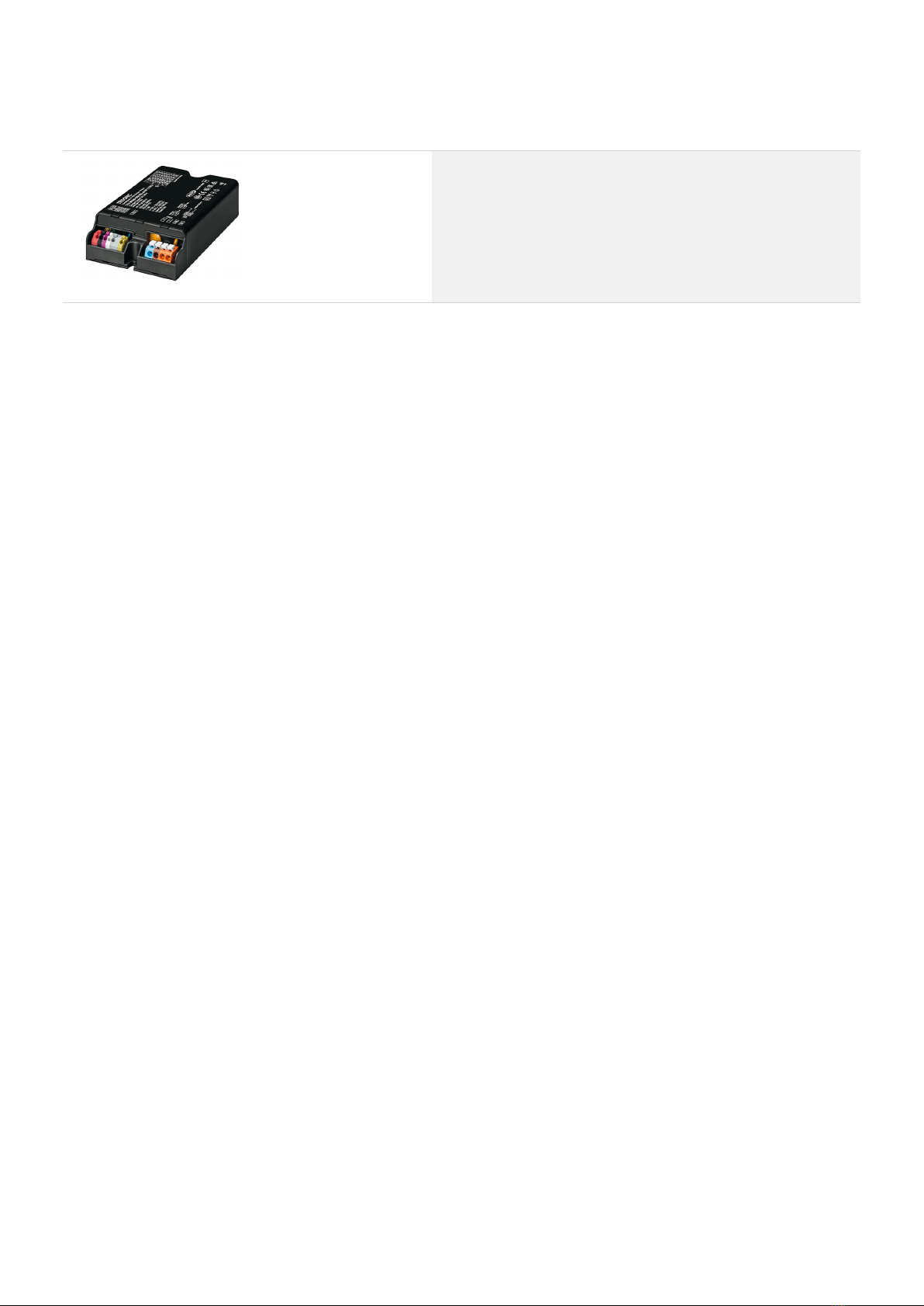
Housing variant compact potted
...
Compact shape for installation inside the luminaire casing
(in-built)
_
Typical area of application: Road, street, industry_

Manual LCO EXC3/ADV3 OTD | 03-2020 | 1.2 | en
Adjustable output current
c12 / 63
Adjustable output current EXC3
The output current can be adjusted via NFC, DALI V2-DT6, ready2mains
Adjustable output current ADV3
The output current can be adjusted via NFC, ready2mains
Adjusting the output current via DALI or ready2mains
Further information about DALI (see ) or ready2mains (see ) can be found in the correspondingDALI, p. 54 ready2mains, p. 56
function description of the DALI manual (see ).Reference list, p. 62
Adjusting the output current via NFC
The NFC Interface allows wireless communication with the LED Driver. This interface offers the option to write configuration and to
read configuration, errors and events with the companionSUITE.
A correct communication between the LED Driver and the NFC antenna can only be guaranteed if the Driver is directly placed on the
antenna.
Any material placed between the LED Driver and the NFC antenna can cause a deterioration of the communication quality. We
recommend the use of following NFC antennas: www.tridonic.com/nfc-readers
NFC is compliant with ISO/IEC 15963 standard.
Output voltage
The output voltage range results from the selected current. More information can be found in the data sheet (see Reference list, p.
).62
The output current can be adjusted via NFC, DALI (only EXC3) or ready2mains. The diagrams below show the forward voltage ranges
as a function of the output current and are intended as a guide.
For detailed values and an explanation of the methods available please refer to the data sheets (see ).Reference list, p. 62
...

Manual LCO EXC3/ADV3 OTD | 03-2020 | 1.2 | en
Compatibility between LED module and LED Driver
c13 / 63
There are two stages involved in the check for compatibility between the LED module and the LED Driver.
Comparison of data sheet values with a 5-point guideline
Different values for the two devices need to be considered when comparing the data sheets. The following table shows which values
are involved and which requirements they must meet.
Comparison
of…
Value in LED
module
Value in LED
Driver Detailed procedure
(1) Current I @HO
rated >= Output current
turn page... ->
Imax >= Output current +
tolerances
...
The requirements for operating together can be checked by comparing the data sheets_
Subsequent practical tests can ensure that there are no unexpected problems during actual operation_
Determine forward current of module_
Check whether LED Driver can be operated with the same output
current
_
Check whether of module is greater than or equal to outputImax
current of LED Driver (including tolerances)
_
½CAUTION!
!The Imax can be temperature dependent
Refer to the derating curve of the LED module data sheet.

Manual LCO EXC3/ADV3 OTD | 03-2020 | 1.2 | en
Compatibility between LED module and LED Driver
c14 / 63
Comparison
of…
Value in LED
module
Value in LED
Driver Detailed procedure
(2) Voltage Min. forward
voltage
> Min. output
voltage
Max. forward
voltage
< Max. output
voltage
Min. forward
voltage
@ min. dim
level
> Min. output
voltage
Only relevant for dimmable LED Driver !
(3) LF current
ripple
Max.
permissible
LF current
ripple
>= Output LF
current ripple
(<120Hz)
(4) Max. peak
current
Max.
permissible
peak current
> Max. output
current peak
(5) Power
(pertinent for
multi channel
LED Driver)
Min. power
consumption
> Min. output
power
Max. power
consumption
< Max. output
power
Check whether voltage range of LED module is completely within the
voltage range of LED Driver
_
½CAUTION!
!The forward voltage is temperature dependent
Refer to the Vf/t diagram in the data sheet.
p
INOTICE
To ensure full dimming performance the forward voltage of the LED
module at min. dim level must be greater than or equal to the min.
output voltage of the driver.
Determine the forward voltage of the LED module at lowest dim level_
In case there is no data available for the LED module at lowest dim
level: take the min. forward voltage minus 20% as an approximation
_
Check whether the forward voltage of the LED module is greater
than or equal to the min. output voltage of the driver
_
Check whether max. permissible LF current ripple of LED module is
greater than or equal to output LF current ripple of LED Driver
_
Check whether max. permissible peak current of LED module is
greater than max. output current peak of LED Driver
_
Check whether power range of LED module is completely within
output power range of LED Driver
_

Manual LCO EXC3/ADV3 OTD | 03-2020 | 1.2 | en
Compatibility between LED module and LED Driver
c15 / 63
Practical tests
The following aspects must be checked:
Technical aspects
Visual aspects
When conducting the tests the following conditions must be considered:
Conditions
½CAUTION!
Following the comparison of the data sheet values a practical test is required. Only a practical test can ensure that the system
luminaire, LED Driver , , ) .components ( LED module wiring are coordinated and working properly
Transient behaviour_
Colour shift_
Connection during operation_
Parasitic capacitance_
Flickering_
Stroboscopic effect (video applications)_
Dimming behaviour_
Colour change/stability_
Luminous flux_
All tolerances_
Entire temperature range_
Different output voltage ranges (incl. no load)_
Entire dimming range_
Short circuit_
INOTE
If the values are slightly over or under the specified threshold values or if there are any other concerns or questions please contact
your 1st level technical support.

Manual LCO EXC3/ADV3 OTD | 03-2020 | 1.2 | en
Compatibility between LED module and LED Driver
c16 / 63
Application of the 5-point guideline
The compatibility check with the 5-point guideline is shown here using two examples.
Example 1
Comparison data for LED Driver
LED Driver
Designation LCA 75W 250–750mA one4all C PRE OTD
Manufacturer TRIDONIC
Data sheet values of LED Driver
Output current 700 mA
Output current tolerance ± 3 %
Min. output voltage 45 V (1)
Max. output voltage 107 V (1)
Output LF current ripple ± 5 %
Max. output current peak Output current + 40 %
Output power 75.0 W
(1) Values at 700 mA
Manual LCO EXC3/ADV3 OTD | 03-2020 | 1.2 | en
Compatibility between LED module and LED Driver
c17 / 63
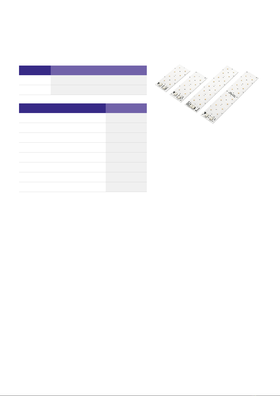
Comparison data for LED module
LED module
Designation RLE G1 49x223mm 4000lm 830 PL1 EXC OTD
Manufacturer Tridonic
Data sheet values of LED module
Forward current 700 mA
Max. DC forward current 1400 mA
Typ. forward voltage 33 V +/-10 % (1)
Min. forward voltage 43.6 V (1)
Max. forward voltage 49.8 V (1)
Max. permissible LF current ripple 1800 mA
Max. permissible peak current 2,000 mA
Power draw 32.14 W
(1) Values at 700 mA
Questions
...
Is the LED Driver able to operate two modules?_
Can the required luminous flux of 3,000 lm be achieved with this combination?_

Manual LCO EXC3/ADV3 OTD | 03-2020 | 1.2 | en
Compatibility between LED module and LED Driver
c18 / 63
Procedure
Comparison of data sheet values
Comparison
of…
Value
in LED module
Value in
LED Driver Result Explanation
(1) Current 700 mA = 700 mA
1400 mA >= 721 mA
(2) Voltage 87.2 V > 45 V
99.6 V < 107 V
(3) LF
current
ripple
1800 mA > 757,05 mA
(4) Max.
peak current
2000 mA > 980 mA
(5) Power 64.8 W < 75.0 W
Result
All the values meet the requirements. The components are mutually compatible.
With 2 modules a luminous flux of 3,713 lm will be achieved.
To produce a luminous flux of 3,000 lm, the two LED modules
must be operated with a forward current of 700 mA.
_
The LED Driver can be set so that it delivers precisely this value
of 700 mA as the output current.
_
The output current of the LED Driver including tolerances (700
mA + 3 % = 721 mA) is less than or equal to the max. DC forward
current of the LED module (1400 mA).
_
The voltage range of the LED module (2 x 43.6 V = 87.2 V; 2 x
49.8 V = 99.6 V) lies completely within the voltage range of the
LED Driver (45 - 107 V).
_
The Output LF current ripple (5 % of output current plus
tolerances: [700 mA + 3 %] x 1.05 = 757,05 mA) of the LED
Driver is less than the max. permissible LF current ripple of the
LED module (1800 mA).
_
The max. output current peak of the LED Driver (700 mA + 40 %
= 980 mA) is less than the max. permissible peak current with
which the LED module can be operated (2,000 mA).
_
The power draw of the LED module (64.8 W) is less than the
output power of the LED Driver (75.0 W).
_
Manual LCO EXC3/ADV3 OTD | 03-2020 | 1.2 | en
Compatibility between LED module and LED Driver
c19 / 63
Example 2
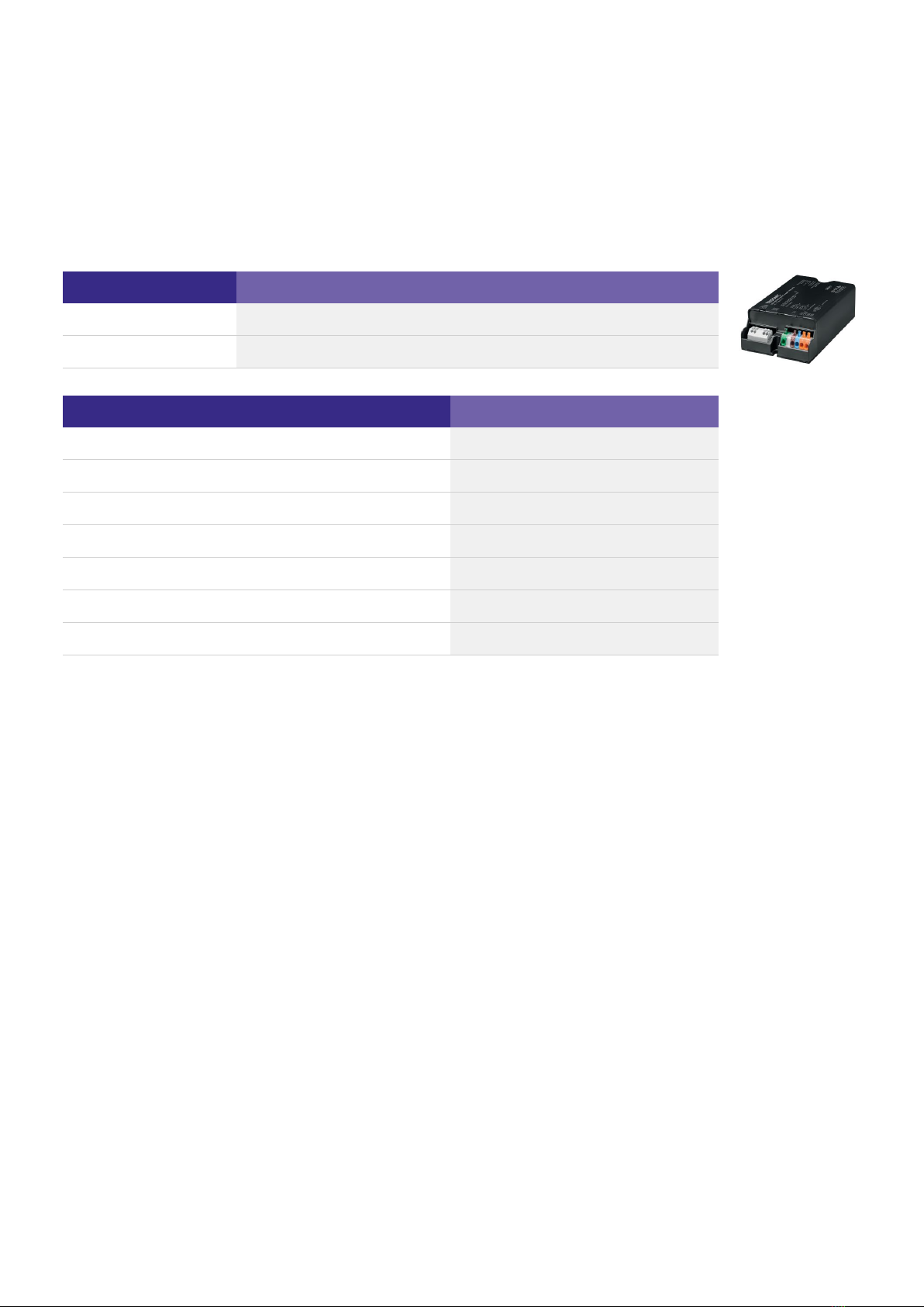
Comparison data for LED Driver
LED Driver
Designation LCA 75W 250–750mA one4all C PRE OTD
Manufacturer TRIDONIC
Data sheet values of LED Driver
Output current 700 mA
Output current tolerance ± 3 %
Min. output voltage 45 V (1)
Max. output voltage 107 V (1)
Output LF current ripple ± 5 %
Max. output current peak Output current + 40 %
Output power 75.0 W
(1) Values at 700 mA

Manual LCO EXC3/ADV3 OTD | 03-2020 | 1.2 | en
Compatibility between LED module and LED Driver
c20 / 63
Comparison data for LED module
LED module
Designation Fictitious LED module
Manufacturer Other manufacturer
Data sheet values of LED module
Forward current 700 mA
Max. DC forward current 1,050 mA
Typ. forward voltage 39.5 V +/-10 % (1)
Min. forward voltage 35.55 V (1)
Max. forward voltage 43.45 V (1)
Max. permissible LF current ripple 630 mA
Max. permissible peak current 1,500 mA
Power draw 19.75 W
(1) Values at 700 mA
Questions
...
Are the two components mutually compatible?_
Can the required luminous flux of 1,800 lm be achieved with this combination?_
This manual suits for next models
1
Table of contents
Other Tridonic DC Drive manuals


Popular DC Drive manuals by other brands

Selec
Selec VFD Series user manual

WEG
WEG CFW100A01P6S220 Quick installation guide

Phoenix Mecano
Phoenix Mecano DEWERT MEGAMAT 2 installation instructions

Control Techniques
Control Techniques Mentor II user guide

ZIEHL-ABEGG
ZIEHL-ABEGG ZETADYN 3C-ZAdyn4C technical information

DURAPULSE
DURAPULSE GS20A quick start guide

Moons'
Moons' SR4-Plus user manual

Lenze
Lenze SMD operating instructions

YASKAWA
YASKAWA CIMR-V7AM Technical manual

Becker
Becker E12a Assembly and operating instructions

Aumuller
Aumuller KSA TWIN S12 24V series Assembly and commissioning instructions

Rockwell Automation
Rockwell Automation CNMD180W0ENNNC1 user manual


