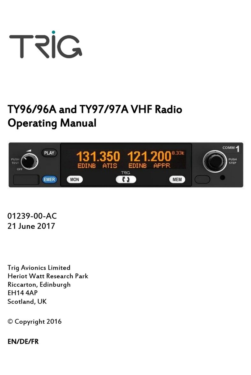
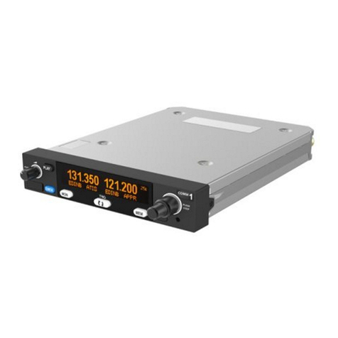
trig TY96A User manual

TY96/96A and TY97/97A VHF Radio Installation
Manual
01238-00-AJ
26 September 2018
Trig Avionics Limited
Heriot Watt Research Park
Riccarton, Currie
EH14 4AP
Scotland, UK
Copyright Trig Avionics Limited, 2015

This page intentionally left blank

TY96/96A and TY97/97A VHF Radio Installation Manual 26 September 2018
01238-00 Issue AJ
______________________
Trig Avionics Limited Page i
CONTENTS
1. PREFACE.......................................................................................................................................1
1.1 PURPOSE....................................................................................................................................1
1.2 SCOPE........................................................................................................................................1
1.3 CHANGES FROM PREVIOUS ISSUE..............................................................................................1
1.4 DOCUMENT CROSS-REFERENCES ..............................................................................................1
2. INTRODUCTION ..........................................................................................................................2
2.1 TY96 AND TY97 DESCRIPTION.................................................................................................2
2.2 INTERFACES...............................................................................................................................2
3. TECHNICAL SPECIFICATIONS...............................................................................................4
3.1 TY96 VHF RADIO (TRIG PART NUMBER 01226-00-01)............................................................4
3.2 TY97 VHF RADIO (TRIG PART NUMBER 01228-00-01)............................................................4
3.3 TY96A VHF RADIO (TRIG PART NUMBER 01787-00-01).........................................................5
3.4 TY97A VHF RADIO (TRIG PART NUMBER 01789-00-01).........................................................6
3.5 PHYSICAL SPECIFICATIONS (IN TRAY).......................................................................................6
3.6 LOW VOLTAGE OPERATION.......................................................................................................6
3.7 INSTALLATION APPROVAL.........................................................................................................7
3.8 NON-ETSO FUNCTIONS ............................................................................................................7
4. UNIT AND ACCESSORIES SUPPLIED.....................................................................................8
4.1 TY96 VHF RADIO ITEMS...........................................................................................................8
4.2 TY96A VHF RADIO ITEMS........................................................................................................8
4.3 TY97 VHF RADIO ITEMS...........................................................................................................8
4.4 TY97A VHF RADIO ITEMS........................................................................................................8
4.5 INSTALLATION KIT....................................................................................................................9
4.6 REQUIRED ITEMS.......................................................................................................................9
5. INSTALLATION ......................................................................................................................... 10
5.1 UNPACKING AND INSPECTING EQUIPMENT..............................................................................10
5.2 INSTALLATION OVERVIEW ...................................................................................................... 10
5.3 COOLING REQUIREMENTS .......................................................................................................11
5.4 ELECTRICAL CONNECTIONS ....................................................................................................11
5.4.1 Orientation Diagram ...................................................................................................... 12
5.4.2 D Connector Crimp Terminals .......................................................................................12
5.4.3 Power and Ground Wiring ............................................................................................. 13
5.4.4 Stereo Wiring Considerations.........................................................................................13
5.4.5 Mono Wiring Considerations..........................................................................................13
5.4.6 Audio Wiring................................................................................................................... 13
5.4.7 Example Wire Harness ................................................................................................... 15
5.5 ANTENNA INSTALLATION........................................................................................................15
5.5.1 Antenna Ground Plane ................................................................................................... 16

TY96/96A and TY97/97A VHF Radio Installation Manual 26 September 2018
01238-00 Issue AJ
______________________
Page ii Trig Avionics Limited
5.5.2 Antenna Cable ................................................................................................................16
5.5.3 BNC Connection.............................................................................................................16
5.6 INTERFACE DETAILS................................................................................................................17
5.6.1 Speaker Output ............................................................................................................... 17
5.6.2 Headphone Outputs ........................................................................................................17
5.6.3 Mono Audio Output ........................................................................................................17
5.6.4 Transmit Interlock ..........................................................................................................17
5.6.5 Lighting Bus Input ..........................................................................................................17
5.6.6 PTT1/2 Key Input............................................................................................................17
5.6.7 Intercom Key Input .........................................................................................................17
5.6.8 Auxiliary Audio Input .....................................................................................................18
5.6.9 Music Audio Input........................................................................................................... 18
5.6.10 Microphone Input ........................................................................................................... 18
5.6.11 RS232 Input/Output ........................................................................................................18
5.6.12 Remote Flip-Flop............................................................................................................18
5.6.13 Power Input ....................................................................................................................18
5.6.14 Ground Returns .............................................................................................................. 18
6. INSTALLATION SETUP AND TEST.......................................................................................19
6.1 INITIAL POWER ON..................................................................................................................19
6.2 CONFIGURATION ITEMS...........................................................................................................19
6.2.1 Intercom Volume............................................................................................................. 19
6.2.2 Intercom Squelch............................................................................................................19
6.2.3 Music Volume .................................................................................................................19
6.2.4 Music Muting.................................................................................................................. 20
6.2.5 Frequency Step Size........................................................................................................20
6.2.6 Auxiliary Input Volume...................................................................................................20
6.2.7 Auxiliary Input Muting ................................................................................................... 20
6.2.8 Sidetone Volume ............................................................................................................. 20
6.2.9 Radio Squelch................................................................................................................. 20
6.2.10 Audio Test Tones ............................................................................................................20
6.2.11 Microphone gain adjustment .......................................................................................... 20
6.2.12 LCD Dim Point............................................................................................................... 21
6.2.13 LCD Brightness Curve....................................................................................................21
6.2.14 Single PTT Mode ............................................................................................................21
7. POST INSTALLATION CHECKS ............................................................................................ 22
8. NORMAL OPERATION.............................................................................................................23
8.1 OVERVIEW ..............................................................................................................................23
8.2 DISPLAY..................................................................................................................................23
8.3 ON/OFF VOLUME KNOB..........................................................................................................23

TY96/96A and TY97/97A VHF Radio Installation Manual 26 September 2018
01238-00 Issue AJ
______________________
Trig Avionics Limited Page iii
8.4 TUNING KNOBS .......................................................................................................................23
8.5 FLIP-FLOP BUTTON..................................................................................................................23
8.6 MON BUTTON.........................................................................................................................24
8.7 MEM BUTTON ........................................................................................................................24
8.8 PLAY BUTTON .......................................................................................................................24
8.9 EMER BUTTON.......................................................................................................................24
8.10 SAVING AND LOADING THE FREQUENCY DATABASE............................................................... 24
8.11 GENERAL LOW TEMPERATURE OPERATION ............................................................................24
8.12 WARNING MESSAGES..............................................................................................................24
8.13 FAULT ANNUNCIATION ...........................................................................................................25
9. CONTINUED AIRWORTHINESS ............................................................................................26
9.1 CLEANING THE FRONT PANEL .................................................................................................26
10. LIMITED WARRANTY..........................................................................................................27
11. ENVIRONMENTAL QUALIFICATION FORMS...............................................................28
12. INSTALLATION DRAWINGS ..............................................................................................32
13. WIRING DIAGRAMS.............................................................................................................34
14. USB FILE FORMAT ...............................................................................................................40
14.1 USB COMPATIBILITY ..............................................................................................................41


TY96/96A and TY97/97A VHF Radio Installation Manual 26 September 2018
01238-00 Issue AJ
______________________
Trig Avionics Limited Page 1
1. Preface
1.1 Purpose
This manual describes the physical and electrical characteristics and the installation requirements for a
TY96 or TY97 VHF and TY96A or TY97A VHF radio.
1.2 Scope
This manual applies to the installation of the TY96, TY97 and TY96A, TY97A VHF radio.
At the publication date of this manual the software version identifier for the TY96/TY97 is 1.7 and the
FPGA version identifier is 1.1. The software and FPGA versions are subject to change without notice.
1.3 Changes from Previous Issue
Numerous small editorial changes.
1.4 Document Cross-References
01239-00
TY96 TY96A and TY97 TY97A VHF Radio Operating Manual
AC
ETSO 2C169a
VHF Radio communication receiving equipment operating within the
radio frequency range 117.975 –137 MHz
EASA
TSO C169a
Minimum Operational Performance standards for Airborne Radio
Communications equipment standards
FAA
ETSO 2C128
Devices that prevent blocked channels used in two-way radio
communications due to unintentional transmissions
EASA
TSO C128a
Equipment that prevents blocked channels used in two-way radio
communications due to unintentional transmissions
FAA

TY96/96A and TY97/97A VHF Radio Installation Manual 26 September 2018
01238-00 Issue AJ
______________________
Page 2 Trig Avionics Limited
2. Introduction
2.1 TY96 and TY97 Description
The TY96 and TY97 VHF radio systems are ED-23C compliant class C (25 kHz offset carrier) and
class H1 and H2 (8.33 kHz offset carrier) VHF radios. The TY96 has a nominal power output of 10
watts, and meets the power output requirements for Class 3 and Class 5. The TY97 has a nominal
power output of 16 watts, and meets the power output requirements for Class 3 and Class 5. The TY96
and TY97 are certified to ETSO 2C169a, 2C128a, TSO C169a and TSO C128a.
The TY96A and TY97A are variants that use 25 KHz channel spacing and are ED-23C compliant class
C (25 kHz offset carrier) VHF radios. The TY96A has a nominal power output of 10 watts, and meets
the power output requirements for Class 4. The TY97A has a nominal power output of 16 watts, and
meets the power output requirements for Class 3. The TY96A and TY97A are certified to ETSO
2C169a, 2C128a, TSO C169a and TSO C128a.
Other than the difference in channel spacing the TY96A/97A variants are identical and all references to
the TY96/97 also apply to the TY96A/97A unless otherwise stated.
The TY96 can be powered from either a 14 volt nominal or 28 volt nominal DC power supply with no
configuration changes required. The TY97 requires a 28 volt nominal DC power supply.
2.2 Interfaces
At the rear, the VHF radio unit has a 25 way D-type connector and single antenna connector for blind
mating with the corresponding connectors in the mounting tray. The 25 way D-type interface provides
the following services:
INPUTS
DESCRIPTION
Power input
The TY96 operates on 11 to 33 volts DC. The TY97 operates on 22 to 33
volts DC.
Lighting bus input
Connects to the aircraft lighting bus and is used to adjust the switch lighting
intensity.
RS232 input
An optional input to allow preloading of frequencies, generally from a GPS.
Push-to-talk inputs
There are two push to talk inputs corresponding to the two microphones.
For backward compatibility with older installations both microphones can
optionally be gated by a single PTT input.
External flip-flop input
An optional keyswitch input to enable remote transfer of primary and
secondary frequencies
Intercom keyswitch
An optional input to allow the intercom to be switch controlled.
Microphone inputs
There are two microphone inputs, suitable for conventional aircraft
microphones.
Auxiliary audio input
A single connection to allow audio annunciators or ident tones to be routed
to the headphones and speaker. Auxiliary audio input is not routed to mono
audio output.
Music audio input
A two channel music input to allow connection of a stereo audio signal of
1.5Vrms into a 600 ohms load. Audio is routed to the headphones only.
OUTPUTS
Speaker output
A speaker output suitable for a cabin speaker with impedance of 4 ohms or
greater.
Audio routing: Received audio and auxiliary input.

TY96/96A and TY97/97A VHF Radio Installation Manual 26 September 2018
01238-00 Issue AJ
______________________
Trig Avionics Limited Page 3
Headphone outputs
Two stereo headphone outputs suitable for conventional aircraft headsets
with impedance in the region of 150 –600 ohms.
Audio routing: Intercom, received audio, auxiliary and music inputs,
transmitter sidetone
Mono audio output
A mono audio output designed to connect to an aircraft audio panel with an
impedance of 600 ohms.
Audio routing: Received audio, transmitter sidetone

TY96/96A and TY97/97A VHF Radio Installation Manual 26 September 2018
01238-00 Issue AJ
______________________
Page 4 Trig Avionics Limited
3. Technical Specifications
3.1 TY96 VHF Radio (Trig Part Number 01226-00-01)
Specification
Characteristics
Compliance
ETSO 2C169a Class C, E, H1, H2, 4, 6, ETSO 2C128,
TSO C169a Class C, E, 4, 6, TSO C128a
FCC Identification
VZI01228
Applicable documents
EUROCAE ED-23C, EUROCAE ED-67, EUROCAE ED-
14F (RTCA DO-160F), RTCA DO-186B, RTCA DO-207
Software
ED-12B (RTCA DO-178B) Level B
Power Requirements
11 –33 volts DC. Typical 6.3 watts @ 14 volts.
Altitude
55,000 feet
Humidity
95% @ +50C for 6 hours; 85% @ +38C for 16 hours.
Tested to Category A in DO-160G
Operating Temperature
-20C to +55C
Transmitter Frequency
118.000 MHz to 136.992 MHz; 760 channels at 25 kHz
spacing, 2280 channels at 8.33 kHz spacing.
Transmitter Power
10 watts nominal carrier power
Transmitter Modulation
5K6 A3E
Stuck-mic timeout
35 seconds
Transmitter Duty Cycle
100% transmit is possible (subject to stuck mic timeout)
Receiver Frequency
118.000 MHz to 136.992 MHz; 760 channels at 25 kHz
spacing, 2280 channels at 8.33 kHz spacing.
Receiver Sensitivity
< 5uV for 6 dB SINAD
AGC Characteristic
< 6dB variation 5 uV to 100 mV EMF
3.2 TY97 VHF Radio (Trig Part Number 01228-00-01)
Specification
Characteristics
Compliance
ETSO 2C169a Class C, E, H1, H2, 3, 5, ETSO 2C128,
TSO C169a Class C, E, 3, 5, TSO C128a
FCC Identification
VZI01228
Applicable documents
EUROCAE ED-23C, EUROCAE ED-67, EUROCAE ED-
14F (RTCA DO-160F), RTCA DO-186B, RTCA DO-207
Software
ED-12B (RTCA DO-178B) Level B
Power Requirements
22 –33 volts DC. Typical 6.3 watts @ 28 volts.
Altitude
55,000 feet
Humidity
95% @ +50C for 6 hours; 85% @ +38C for 16 hours.
Tested to Category A in DO-160G
Operating Temperature
-20C to +55C
Transmitter Frequency
118.000 MHz to 136.992 MHz; 760 channels at 25 kHz
spacing, 2280 channels at 8.33 kHz spacing.

TY96/96A and TY97/97A VHF Radio Installation Manual 26 September 2018
01238-00 Issue AJ
______________________
Trig Avionics Limited Page 5
Transmitter Power
16 watts nominal carrier power
Transmitter Modulation
5K6 A3E
Stuck-mic timeout
35 seconds
Transmitter Duty Cycle
25%
Receiver Frequency
118.000 MHz to 136.992 MHz; 760 channels at 25 kHz
spacing, 2280 channels at 8.33 kHz spacing.
Receiver Sensitivity
< 5uV for 6 dB SINAD
AGC Characteristic
< 6dB variation 5 uV to 100 mV EMF
3.3 TY96A VHF Radio (Trig Part Number 01787-00-01)
Specification
Characteristics
Compliance
ETSO 2C169a Class C, 4, ETSO 2C128, TSO C169a Class
C, 4, TSO C128a
FCC Identification
VZI01228
Applicable documents
EUROCAE ED-23C, EUROCAE ED-67, EUROCAE ED-
14F (RTCA DO-160F), RTCA DO-186B, RTCA DO-207
Software
ED-12B (RTCA DO-178B) Level B
Power Requirements
11 –33 volts DC. Typical 6.3 watts @ 14 volts.
Altitude
55,000 feet
Humidity
95% @ +50C for 6 hours; 85% @ +38C for 16 hours.
Tested to Category A in DO-160G
Operating Temperature
-20C to +55C
Transmitter Frequency
118.000 MHz to 136.992 MHz; 760 channels at 25 kHz
spacing.
Transmitter Power
10 watts nominal carrier power
Transmitter Modulation
5K6 A3E
Stuck-mic timeout
35 seconds
Transmitter Duty Cycle
100% transmit is possible (subject to stuck mic timeout)
Receiver Frequency
118.000 MHz to 136.992 MHz; 760 channels at 25 kHz
spacing.
Receiver Sensitivity
< 5uV for 6 dB SINAD
AGC Characteristic
< 6dB variation 5 uV to 100 mV EMF

TY96/96A and TY97/97A VHF Radio Installation Manual 26 September 2018
01238-00 Issue AJ
______________________
Page 6 Trig Avionics Limited
3.4 TY97A VHF Radio (Trig Part Number 01789-00-01)
Specification
Characteristics
Compliance
ETSO 2C169a Class C, 3, ETSO 2C128, TSO C169a
Class C, 3, TSO C128a
FCC Identification
VZI01228
Applicable documents
EUROCAE ED-23C, EUROCAE ED-67, EUROCAE ED-
14F (RTCA DO-160F), RTCA DO-186B, RTCA DO-207
Software
ED-12B (RTCA DO-178B) Level B
Power Requirements
22 –33 volts DC. Typical 6.3 watts @ 28 volts.
Altitude
55,000 feet
Humidity
95% @ +50C for 6 hours; 85% @ +38C for 16 hours.
Tested to Category A in DO-160G
Operating Temperature
-20C to +55C
Transmitter Frequency
118.000 MHz to 136.992 MHz; 760 channels at 25 kHz
spacing.
Transmitter Power
16 watts nominal carrier power
Transmitter Modulation
5K6 A3E
Stuck-mic timeout
35 seconds
Transmitter Duty Cycle
25%
Receiver Frequency
118.000 MHz to 136.992 MHz; 760 channels at 25 kHz
spacing.
Receiver Sensitivity
< 5uV for 6 dB SINAD
AGC Characteristic
< 6dB variation 5 uV to 100 mV EMF
3.5 Physical Specifications (in Tray)
The TY96 and TY97 are the same size and weight.
Specification
Characteristics
Height
33 mm (1.30”)
Width
159 mm (6.25”)
Length
231 mm (9.1”) behind the panel
273 mm (10.77”) overall
Weight
2.33lbs. (1.06Kg)
3.6 Low Voltage Operation
Normal operating voltage for the TY96 is any voltage between 11 and 33 volts, whilst normal
operating voltage for the TY97 is any voltage between 22 and 33 volts. At these voltages all functions
behave normally, and transmitter power meets the applicable Class requirements of ED-23C.
The radio will continue to operate at a lower voltage than these ranges. As the available voltage falls,
the transmitter output power will be reduced, and at 9 volts the nominal transmitter power will be
approximately 2.5 watts. The transmitter will be inhibited below 8 volts.
The receiver also works below the nominal voltage. All receiver functions will work normally, but as a

TY96/96A and TY97/97A VHF Radio Installation Manual 26 September 2018
01238-00 Issue AJ
______________________
Trig Avionics Limited Page 7
safety feature to preserve battery power in an emergency, at 10 volts or below the available speaker
volume will reduce.
In addition a warning message, “Low Volts”, will be displayed on the screen when the bus voltage falls
below 10 volts in a TY96, or 18 volts in a TY97.
3.7 Installation Approval
The conditions and tests required for the TSO approval of the TY96 and TY97 VHF radios are
minimum performance standards. It is the responsibility of those installing this VHF radio on or within
a specific type or class of aircraft to determine that the aircraft operating conditions are within the TSO
standards. The VHF radio may be installed only if further evaluation by the user/installer documents
an acceptable installation that is approved by the appropriate airworthiness authority.
3.8 Non-ETSO Functions
The TY96/TY97/TY96A/TY97A radios contain the following non-ETSO functions:
•Two place intercom.
•Audio routing and control for auxiliary audio input and stereo music input.
The operation of each of these functions is described later in this manual.

TY96/96A and TY97/97A VHF Radio Installation Manual 26 September 2018
01238-00 Issue AJ
______________________
Page 8 Trig Avionics Limited
4. Unit and Accessories supplied
4.1 TY96 VHF radio Items
The TY96 VHF radio includes the following items:
Unit Description
Qty
Part Number
TY96 VHF Radio
1
01226-00-01
TY96/TY97 Installation Kit
1
01472-00
TY96/TY97 Mounting Tray
1
01368-00
TY96 TY96A and TY97 TY97A Pilots Operating Handbook
1
01239-00
4.2 TY96A VHF radio Items
The TY96A VHF radio includes the following items:
Unit Description
Qty
Part Number
TY96A VHF Radio
1
01787-00-01
TY96/TY97 Installation Kit
1
01472-00
TY96/TY97 Mounting Tray
1
01368-00
TY96 TY96A and TY97 TY97A Pilots Operating Handbook
1
01239-00
4.3 TY97 VHF radio Items
The TY97 VHF radio includes the following items:
Unit Description
Qty
Part Number
TY97 VHF Radio
1
01228-00-01
TY96/TY97 Installation Kit
1
01472-00
TY96/TY97 Mounting Tray
1
01368-00
TY96 TY96A and TY97 TY97A Pilots Operating Handbook
1
01239-00
4.4 TY97A VHF radio Items
The TY97A VHF radio includes the following items:
Unit Description
Qty
Part Number
TY97 VHF Radio
1
01789-00-01
TY96/TY97 Installation Kit
1
01472-00
TY96/TY97 Mounting Tray
1
01368-00
TY96 TY96A and TY97 TY97A Pilots Operating Handbook
1
01239-00

TY96/96A and TY97/97A VHF Radio Installation Manual 26 September 2018
01238-00 Issue AJ
______________________
Trig Avionics Limited Page 9
4.5 Installation Kit
The TY96/TY97 installation kit includes the following items:
Unit Description
Qty
Part Number
Connector Mounting Plate
1
01369-00
Connector Standard Mount 25 Way D receptacle to M24308
1
00866-00
Crimp Socket Contact, Wire size 20-24 AWG
25
00730-00
D-Sub Shell
1
01440-00
D-Sub Shell Clamp
1
01441-00
D-Sub Shell Cover
1
01442-00
BNC Female to Blind Mate Adaptor
1
01410-00
Washer, 7/16", Plain, Stainless Steel
1
00241-00
Circlip, 7/16", External, Stainless Steel
1
00242-00
Washer, 7/16", Wave, Stainless Steel
1
00317-00
Screw, Pozidriv, Csk Head, M2.5 x 5mm, Pre Patch
2
01020-00
Screw, Pozidriv, Pan Head, M2.5 x 5mm, Pre Patch
6
01021-00
Screw, Pozidriv, Pan Head, M2.5 x 8mm, Pre Patch
4
01024-00
Screw, Philips Csk head, 4-40 UNC x 0.312", Pre Patch
2
01397-00
Washer, M2.5 Rect Sect, Spring
6
01473-00
User Label Sheet
USB Flash Drive
1
1
01412-00
01646-00
4.6 Required Items
Additional items you will require, but which are not in the TY96/TY97 package, include:
•Antenna and fixing hardware. The TY96 or TY97 are compatible with any standard 50 ohm
vertically polarised antenna with a VSWR better than 2.5:1.
•Cables. You need to supply and fabricate all required cables. Guidance on cable types is
given in section 5.
•Fixings. To secure the VHF radio tray to the airframe you will need at least 6 flat head screws
and self-locking nuts. If the aircraft does not have existing mounting provisions you may need
to fabricate additional brackets to support the VHF radio tray.
Existing wiring provisions from a previously installed radio may be re-used provided it is in
satisfactory condition.

TY96/96A and TY97/97A VHF Radio Installation Manual 26 September 2018
01238-00 Issue AJ
______________________
Page 10 Trig Avionics Limited
5. Installation
5.1 Unpacking and Inspecting Equipment
Carefully unpack the VHF radio and make a visual inspection of the unit for evidence of any damage
incurred during shipment. If the unit is damaged, notify the shipping company to file a claim for the
damage. To justify your claim, save the original shipping container and all packaging materials.
5.2 Installation Overview
The TY96/TY97 VHF Radio must be mounted rigidly in the aircraft panel. The following installation
procedure should be followed, remembering to allow adequate space for installation of cables and
connectors.
•Select a position in the panel that is not too close to any high external heat source. (The radio
is not a significant heat source itself and does not need to be kept away from other devices for
this reason).
•Prepare the instrument panel to ensure the radio mounting tray can be secured using the
mounting holes in the tray. The front edge of the mounting tray should sit flush with the
instrument panel.
•It is advisable to complete the 25 way D-sub cable harness at this point before securing the
mounting tray into the aircraft. The cable harness and antenna connector can then be secured
to the removable mounting tray plate. Refer to section 5.4 for cable harness details and
section 5.5 for fitting the antenna connector.
•Route the mounting tray plate and cable harness into position, avoiding sharp bends and
placing the cables too near to the aircraft control cables.
•Attach the VHF antenna coax using a BNC connector.
•Clip the mounting tray plate into the mounting tray and secure with M2.5 pan head screws.
Note: The mounting tray plate clips into the mounting tray to aid assembly but must be
secured using screws. The clips alone are not strong enough to retain the back plate when
fitting the radio.
•Secure the mounting tray to the instrument panel via the six (6) mounting holes in the tray. It
is important that the tray is supported at the rear with at least two mounting holes as well as
the front four.
•Check that the VHF radio locking mechanism is correctly oriented by unscrewing the locking
screw using a 3/32” Allen key.
M2.5 back
plate
securing

TY96/96A and TY97/97A VHF Radio Installation Manual 26 September 2018
01238-00 Issue AJ
______________________
Trig Avionics Limited Page 11
•Slide the VHF radio into the secured mounting tray.
•Lock the VHF radio into the mounting tray using a 3/32” Allen key, gently hand tighten the
locking screw.
5.3 Cooling Requirements
The VHF radio meets all applicable ETSO requirements without forced air-cooling. Reasonable air
circulation should be provided.
Attention should be given to the incorporation of cooling provisions to limit the maximum operating
temperature if the TY96 is installed in close proximity to other avionics. The reliability of equipment
operating in close proximity in an avionics bay can be degraded if adequate cooling is not provided.
5.4 Electrical Connections
The TY96 has single 25 way D-type connector which is used for all the data and audio signals. A
single coaxial BNC is used to connect the antenna.
Pin
Signal
Direction
1
Speaker Out
Output
2
Headphone 1 Left Out
Output
3
Headphone 1 Right Out
Output
4
Ground
-
5
Headphone 2 Left Out
Output
6
Headphone 2 Right Out
Output
7
Mono Audio Out
Output
8
Lighting Bus In
Input
9
Ground
-
10
Transmit Interlock In
Input
11
RS232 Out
Output
12
RS232 In
Input
13
Aircraft Power (DC)
-
14
Aux Audio
Input
15
Music Audio Left In
Input
16
Music Audio Right In
Input
17
Ground
-
18
Microphone 1
Input
19
Microphone 2
Input
20
Reserved
Input
21
Remote Flip-Flop
Input
22
Intercom Key
Input
23
PTT1
Input
24
PTT2
Input
25
Aircraft Power (DC)
-

TY96/96A and TY97/97A VHF Radio Installation Manual 26 September 2018
01238-00 Issue AJ
______________________
Page 12 Trig Avionics Limited
Figure 1: Mounting Tray 25 D-type Primary Connector
5.4.1 Orientation Diagram
To assist in connector orientation, the following example shows a typical set of connections. This
diagram shows the expected connector positions when viewed from the radio side of the tray, looking
into the tray from the front.
5.4.2 D Connector Crimp Terminals
The 25 way connector supplied with the TY96 installation kit are MIL standard versions of the popular
sub miniature D type connector family, and use individual crimp terminals and a receptacle. The MIL
specification for this family of connectors is MIL-C-24308. We supply crimp terminals because these
are more reliable than soldered connections, and are easier to assemble in-situ in an aircraft, where
soldering is impractical. They also allow individual wires to be removed and replaced in a receptacle
without replacing the whole connector.
The socket contacts used in the connectors conform to MIL part number M39029/63-368, and are also
suitable for wire gauges from 20 to 24 AWG.
These contacts are widely used in avionics installation, and there are many tools available on the
market that will reliably crimp them to the wiring. Because the contacts are a MIL standard, there is
also a MIL standard for the crimp tool, although other proprietary solutions are available.
25
13
14
1
Power In
25
13
14
1
PTT
1
Intercom Key
enabled when connected to
ground
Mic
1
Mic
2
Ground
Left Right
Headphone 1
Left Right
Headphone 2
Ground
Antenna

TY96/96A and TY97/97A VHF Radio Installation Manual 26 September 2018
01238-00 Issue AJ
______________________
Trig Avionics Limited Page 13
The MIL reference for the basic style of hand tool is M22520/2-01. This style of tool can crimp many
different contact types, and relies on interchangeable "positioners" to hold the actual contact in use.
The MIL reference for the positioner that you need for the crimps we supply is M22520/2-08.
Any tool that complies with these references can be used to crimp these contacts. One of the most
popular vendors of these small hand tools is Daniels Manufacturing Corporation (see
www.dmctools.com). Their AFM8 hand tool complies with M22520/2-01, and their K13-1 positioner
is M22520/2-08 compliant, so the combination will crimp the supplied connectors.
Once crimped, the contacts should be slotted into the rear of the connector shell. Push the contact in
until the retaining tab clicks into place. Tug gently to confirm the contact is locked in place.
5.4.3 Power and Ground Wiring
The peak current consumption of the TY96 on transmit exceeds the current capability of a single pin on
the connector. Both power inputs must be wired, and at least two ground returns must be wired. This
is particularly important when the VHF radio is mounted on a non-conducting surface, such as a
composite structure.
Use 20 AWG wire for the power connection wires.
5.4.4 Stereo Wiring Considerations
The TY96 uses stereo for the headphone connections. It is important to connect the left and right audio
signals correctly to ensure the intercom and dual watch audio is correctly routed to the headphones. A
typical general aviation headset will have the left channel on the tip and the right channel on the ring of
the phones jack.
Intercom Audio
When using the stereo intercom, the audio output will appear more towards the side of the person who
is speaking. For example, when the pilot is speaking, the co-pilot will hear this slightly more in their
left ear than their right.
If the stereo wiring is incorrect then the audio will be routed to the wrong side of the headphones.
Dual Watch Audio
When using the dual watch function, the TY96 will route audio received on the primary channel to the
centre of both headphones. Audio received on the secondary channel will be quieter and routed toward
the right of the headphones.
5.4.5 Mono Wiring Considerations
The TY96 audio wiring can be connected to suit a mono headphone installation. To do this, you must
short the left and right signal wires together at the TY96 end of the loom. This will have the effect of
placing all audio in the centre of the connected headphones and provides the correct level.
This may be relevant when replacing a previous mono VHF radio where you wish to utilise the existing
wiring and mono headset jacks.
5.4.6 Audio Wiring
All wires carrying audio signals should be wired using 22 AWG shielded cable to MIL-C-27500 or
Sleeve
(audio ground)
Ring
(right audio)
Tip
(left audio)

TY96/96A and TY97/97A VHF Radio Installation Manual 26 September 2018
01238-00 Issue AJ
______________________
Page 14 Trig Avionics Limited
equivalent. Mono audio signals should use 2 core shielded cable and stereo signals should use 3 core
shielded cable. One core wire within each shielded cable should be connected to ground; the cable
shield should not be used to carry the audio ground signals.
The cable shield should be connected to ground at the TY96 end only. Do not connect the shield at
both ends of the cable to avoid a ground loop which can increase interference effects.
When terminating shielded cable it is recommended to cut away the cable insulation to expose the
cable shield. At the end of the cable, strip the insulation and shield back at least 90mm. Trim the audio
signal wires back to 30mm, keeping the signal ground wire at least 90mm in length.
The audio signal wires can be terminated with D connector socket contacts that conform to MIL part
number M39029/63-368.
Using a solder sleeve, attach some flat copper braid to the exposed shield and terminate with a crimp
ring. Repeat for all shielded cable and connect the crimp ring terminals to the ground points on the
mounting tray back plate.
Connect the cable shields to the mounting tray back plate along with the signal ground connections.
Secure the ring crimps to the back plate ground lugs using M2.5 screws and spring washers.
15mm
25mm
30mm
60mm
Strip the insulation
to expose the cable
shield
Audio signal
wires
Signal ground
wire
90mm
Solder
Sleeve
Secure shield connection
to the mounting tray
back plate
Ground lugs
(x6)
This manual suits for next models
3
Table of contents
Other trig Radio manuals

