BCM RX680R User manual

RX680R
Intel® R680E support 12th generation Core™ i9, Core i7, Core i5,
Core i3, Pentium, Celeron
Micro-ATX Motherboard
User’s Manual
V1.1

RX680R User’s Manual
2
Content
Safety Information ...................................................................................................... 5
About this guide ......................................................................................................... 7
Typography ................................................................................................................. 8
Packing List ................................................................................................................ 9
Revision History ....................................................................................................... 10
RX680R Motherboard Features ............................................................................... 11
Specifications Summary .......................................................................................... 11
Block Diagram .......................................................................................................... 13
Chapter 1 - Product Introduction ............................................................................ 14
1.1 Before you Proceed ........................................................................................................ 15
1.2 Motherboard Overview .................................................................................................... 15
1.2.1 Placement Direction ............................................................................................................................... 15
1.2.2 Screw Holes ........................................................................................................................................... 16
1.2.3 Motherboard Layout ............................................................................................................................... 17
1.2.4 Layout Content List ................................................................................................................................ 18
1.3 Central Processing Unit (CPU) ....................................................................................... 20
1.3.1 Installing the CPU .................................................................................................................................. 21
1.3.2 Installing the CPU Heatsink and Fan ..................................................................................................... 23
1.3.3 Uninstalling the CPU Heatsink and Fan................................................................................................. 25
1.4 System Memory .............................................................................................................. 26
1.4.1 Overview ................................................................................................................................................ 26
1.4.2 Installing a DIMM ................................................................................................................................... 27
1.4.3 Removing a DDR5 DIMM ...................................................................................................................... 27
1.5 Expansion Card .............................................................................................................. 27
1.5.1 Installing an Expansion Card ................................................................................................................. 28
1.5.2 Configuring an Expansion Card ............................................................................................................. 28
1.5.3 PCI Express x16 slot .............................................................................................................................. 28
1.5.4 PCI Express x4 slot ................................................................................................................................ 29
1.5.5 M.2 connector ........................................................................................................................................ 29
1.6 Jumpers .......................................................................................................................... 30
1.6.1 Clear CMOS (CMOS1)........................................................................................................................... 30
1.6.2 AT/ATX Power Mode Select (AT1) ........................................................................................................ 31
1.6.3 COM POWER SETTING (J56,J45~J48,J25) ......................................................................................... 31
1.6.4 LVDS Panel Power Select (PANEL_SEL1) ........................................................................................... 32
1.6.5 LVDS Blacklight Voltage Selection (BKLVOL1) ..................................................................................... 32
1.7 Connectors...................................................................................................................... 33
1.7.1 Rear panel connectors ........................................................................................................................... 33
1.7.2 CPU and System fan connectors (CPU_FAN1, SYS_FAN1, SYS_FAN2) ........................................... 34

RX680R User’s Manual
3
1.7.3 System Panel (FIO_PANEL) .................................................................................................................. 34
1.7.4 ATX power connectors (ATX24P_1& ATX12V) ..................................................................................... 35
1.7.5 Serial Port connectors (COM1~6) .......................................................................................................... 36
1.7.6 Serial ATA connector (SATA1~4 ) ......................................................................................................... 36
1.7.7 USB connectors (USB2_HR1, USB2_HR2, USB2_HR3, USB2_HR4) ................................................. 37
1.7.8 USB3.2 connector (USB3_HR1) ............................................................................................................ 37
1.7.9 Front Audio connector (FIO_AUD1) ....................................................................................................... 38
1.7.10 Amplifier connector (SPK1) .................................................................................................................. 38
1.7.11 LVDS connector (LVDS1) ................................................................................................................ 389
1.7.12 LVDS Backlight connector (BKLT1) ..................................................................................................... 39
1.7.13 LAN LED status connector (LAN_LED1) ............................................................................................. 40
1.7.14 Chassis intrusion connector (INTRUD1) .............................................................................................. 40
1.7.15 8 bit GPIO header (GPIO_HDR1) ........................................................................................................ 41
1.7.16 SMBUS/I2C/KMBS connectors (J_i2C1, J_SMB1, J57)) ..................................................................... 41
Chapter 2 - BIOS Setup ............................................................................................ 42
2.1 Main Page ....................................................................................................................... 43
2.2 Advanced BIOS Setup .................................................................................................... 44
2.2.1 CPU Configuration ................................................................................................................................. 46
2.2.1.1 Performance-core Information ........................................................................................................................ 48
2.2.2 PCH-FW configuration ........................................................................................................................... 49
2.2.2.1 TPM Configuration ......................................................................................................................................... 50
2.2.3 Trusted Computing ................................................................................................................................. 51
2.2.4 ACPI Settings ......................................................................................................................................... 52
2.2.5 NCT6126D Super IO configuration ........................................................................................................ 53
2.2.5.1 Serial Port 1 Configuration.............................................................................................................................. 54
2.2.5.2 Serial Port 2 Configuration.............................................................................................................................. 55
2.2.5.3 Serial Port 3 Configuration.............................................................................................................................. 56
2.2.5.4 Serial Port 4 Configuration.............................................................................................................................. 57
2.2.5.5 Serial Port 5 Configuration.............................................................................................................................. 58
2.2.5.6 Serial Port 6 Configuration.............................................................................................................................. 59
2.2.5.7 Pallallel Port Configuration ............................................................................................................................. 60
2.2.6 Hardware monitor ................................................................................................................................... 61
2.2.6.1 Smart Fan Function ......................................................................................................................................... 62
2.2.6.1.1 Front Fan Setting .................................................................................................................................... 63
2.2.6.1.2 CPU Fan Setting ..................................................................................................................................... 64
2.2.6.1.3 Rear Fan Setting ..................................................................................................................................... 66
2.2.7 S5 RTC wake settings ............................................................................................................................ 67
2.2.8 AMI Graphic Output Protocol Policy ....................................................................................................... 68
2.2.9 USB configuration .................................................................................................................................. 69
2.2.10 Network Stack Configuration ................................................................................................................ 70

RX680R User’s Manual
4
2.2.11 NVMe Configuration ............................................................................................................................. 71
2.3 Chipset ............................................................................................................................ 72
2.3.1 System Agent (SA) Configuration .......................................................................................................... 73
2.3.1.1 Memory Configuration .................................................................................................................................... 74
2.3.1.2 Graphic Configuration ..................................................................................................................................... 75
2.3.1.3 VMD setup menu ............................................................................................................................................ 76
2.3.2 PCH-IO Configuration ............................................................................................................................ 76
2.3.2.1 PCI Express Configuration .............................................................................................................................. 79
2.3.2.1.1 PCI Express M.2 E .................................................................................................................................. 80
2.3.2.1.2 PCI Express M.2 M ................................................................................................................................. 81
2.3.2.1.3 PCI Express X4 Open End ...................................................................................................................... 82
2.3.2.1.4 PCI Express X4 SLOT3 .......................................................................................................................... 83
2.3.2.1.5 PCI Express X4 SLOT4 .......................................................................................................................... 84
2.3.2.1.6 M.2 E CNVi Configuration ..................................................................................................................... 85
2.3.2.2 SATA Configuration ....................................................................................................................................... 86
2.3.2.3 USB Configuration .......................................................................................................................................... 87
2.3.2.4 HD audio Configuration .................................................................................................................................. 88
2.4 Security ........................................................................................................................... 89
2.4.1 HDD Security ..................................................................................................................................................... 90
2.4.2 Secure Boot ........................................................................................................................................................ 91
2.4.2.1 Key Management ........................................................................................................................................ 92
2.5 Boot Page ....................................................................................................................... 95
2.6 Save & Exit Page ............................................................................................................ 98
2.6.1 AMI FW update interface ................................................................................................................................... 99
2.7 MEBX ............................................................................................................................ 100

RX680R User’s Manual
5
Safety Information
Electrical safety
⚫ To prevent electrical shock hazard, disconnect the power cable from the electrical outlet
before relocating the system.
⚫ When adding or removing devices to or from the system, ensure that the power cables
for the devices are unplugged before the signal cables are connected. If possible,
disconnect all power cables from the existing system before you add a device.
⚫ Before connecting or removing signal cables from the motherboard, ensure that all
power cables are unplugged.
⚫ Seek professional assistance before using an adapter or extension cord. These devices
could interrupt the grounding circuit.
⚫ Make sure that your power supply is set to the correct voltage in your area. If you are
not sure about the voltage of the electrical outlet you are using, contact your local power
company.
⚫ If the power supply is broken, do not try to fix it by yourself. Contact a qualified service
technician or your retailer.
Operation safety
⚫ Before installing the motherboard and adding devices on it, carefully read all the
manuals that came with the package.
⚫ Before using the product, make sure all cables are correctly connected and the power
cables are not damaged. If you detect any damage, contact your dealer immediately.
⚫ To avoid short circuits, keep paper clips, screws, and staples away from connectors,
slots, sockets and circuitry.
⚫ Avoid dust, humidity, and temperature extremes. Do not place the product in any area
where it may become wet.
⚫ Place the product on a stable surface.
⚫ If you encounter technical problems with the product, contact a qualified service
technician or your retailer.
The symbol of the crossed out wheeled bin indicates that the product
(Electrical and electronic equipment) should not be placed in
municipal waste. Check local regulations for disposal of electronic
products.

RX680R User’s Manual
6
Safety Declaration
This device complies with the requirements in Part 15 of the FCC rules. Operation is subject
to the following two conditions:
⚫ This device may not cause harmful interference.
⚫ This device must accept any interference received, including interference that may
cause undesired operation.

RX680R User’s Manual
7
About this guide
This user guide contains the information you need when installing and configuring the
motherboard.
How this guide is organized
This manual contains the following parts:
Chapter 1: Product introduction
This chapter describes the features of the motherboard and the new technology it
supports. This chapter also lists the hardware setup procedures that you have to perform
when installing system components. It includes description of the jumpers and
connectors on the motherboard.
Chapter 2: BIOS setup
This chapter tells how to change system settings through the BIOS Setup menus.
Detailed descriptions of the BIOS parameters are also provided.
Where to find more information
Refer to the following sources for additional information and for product and software updates.
1. Motherboard User’s Manual and Device Drivers
Motherboard User’s Manual and Device Drivers can be downloaded at BCM Advanced
Research website: https://www.bcmcom.com/product_industrialMB_MATX.html
2. Technical Support
If a problem arises with your system and no solution can be obtained from the user’s manual,
please contact your place of purchase or local distributor. Alternatively, please try the following
help resources for further guidance. Visit the BCM Advanced Research website:
https://www.bcmcom.com/
Conventions used in this guide
To make sure that you perform certain tasks properly, take note of the following symbols
used throughout this manual.
DANGER/WARNING: Information to prevent injury to yourself
when trying to complete a task.
CAUTION: Information to prevent damage to the components
when trying to complete a task.
IMPORTANT: Instructions that you MUST follow to complete a
task.
NOTE: Tips and additional information to help you complete a
task.

RX680R User’s Manual
8
Typography
Bold text
Indicates a menu or an item to select
Italics
Used to emphasize a word or a phrase
<Key>
Keys enclosed in the less-than and greater-than sign means
that you must press the enclosed key
Example: <Enter> means that you must press the Enter or
Return key
<Key1>+<Key2>+<Key3>
If you must press two or more keys simultaneously, the key
names are linked with a plus sign (+)
Example: <Ctrl>+<Alt>+<D>
Command
Means that you must type the command exactly as shown,
then supply the required item or value enclosed in
brackets Example: At the UEFI shell, type the command
line:
AfuEfix64 [filename] /B /P /N /X
AfuEfix64 71841100.ROM /B /P /N /X

RX680R User’s Manual
9
Packing List
Before you begin installing your single board, please make sure that the following materials
have been shipped:
⚫1 x RX680R Micro-ATX Main board
⚫1 x I/O Shield
If any of the above items is damaged or missing, please contact your
retailer.

RX680R User’s Manual
10
Revision History
Revision
Revision History
Date
V 1.0
First release version
Oct, 2022
V 1.1 Add BIOS Programming command.
Change Line out port to Green color.
Nov, 2022
RX680R User’s Manual
11
RX680R Motherboard Features
This chapter briefly describes the features of Board RX680R.
The Table summarizes the major features of this board as below:
Specifications Summary
Specifications
System
CPU
Intel® Alder Lake Processor Up to 16 Cores 24 Threads Hybrid,
TDP Max 125W.
LGA1700 Supports Core i9, Core i7, Core i5, Core i3, Pentium,
Celeron
BIOS
Socket Type 256Mb SPI BIOS
System Chipset
Intel® R680E PCH
Memory
4 DIMM Up to 128GB Max Dual Channel DDR5 4400 MHz with ECC
Support 2DPC
Watch Dog Timer
1 ~ 255 sec timer
H/W Status Monitor
CPU & system temperature monitoring
Voltages monitoring
Expansion Slots
1 x Gen 5 PCIe x16 (x16 Physical Black) (Slot 1)
2 x Gen 4 PCIe x4 (x16 Physical Yellow) (Slot 3 & 4)
1 x Gen 3 PCIe x4 Open Ended (Slot 2)
1 x M.2 2242/2280/22110 M Key NVMe (Gen 4 PCIe x4 + SATA III)
1 x M.2 2242/2280/22110 M Key NVMe (Gen 3 PCIe x4 + SATA III)
1 x M.2 2230 E Key with CNVi Support (PCIe x 1 + USB 2.0)
Smart Fan
Yes
Display
Chipset
Intel® UHD Graphics driven by Xe Architecture (CPU Dependent)
Ethernet
LAN1
Intel® I225-LM 2.5 Gigabit Ethernet Controller
LAN2
Intel® I225-LM 2.5 Gigabit Ethernet Controller
Rear I/O Port
Back Panel
4 x DisplayPort Connectors
2 x RJ45+Dual USB 3.2 Stacked Connectors (4 x USB 3.2 Gen 2x1
Ports)
2 x USB 3.2 Gen 2x1 Type-A Connectors
1 x USB 3.2 Gen 2x2 Type-C Connector
RX680R User’s Manual
12
1 x 2 Audio Connector, Green color for line-out, Pink color for Mic-In
Internal I/O Connector
Internal I/O
4 x SATA III Vertical Connectors (Red)
5 x RS-232 Headers with Voltage Selection
1 x RS-232/422/485 Headers with Voltage Selection
1 x PS/2 Header
1 x LPT Header
4 x USB 2.0 Headers with Shroud (8 Ports on Header)
1 x USB 3.2 Gen 1x1 Header with Shroud (2 Ports on Header)
1 x LVDS Header
1 x Backlight Locking Type Header
1 x SPI Header
1 x I2C Header
1 x SMBUS Header
1 x Front Audio Header with Shroud
1 x Amplifier Locking Type Header
1 x Front Panel Headers with
Shroud
1 x 8 bits GPIO Header with Shroud
1 x 4 Pin CPU Fan Header (4 Pin PWM)
2 x 4 Pin Chassis Fan Header (4 Pin PWM)
2 x LAN Status LED Headers
1 x Horizontal Socket Type CMOS Battery Holder
1 x Chassis Intrusion Locking Type Header
1 x eSPI Header
1 x Std. 24 pin ATX Connector
1 x 8 pin ATX 12 Connector
1 x AT/ATX Mode Jumper
Mechanical & Environmental
Operating Temperature
0 C to 60 C
Operating Humidity
5% to 90% non-condensing
Size (LxW)
9.6” (L) x 9.6” (W)
RX680R User’s Manual
13
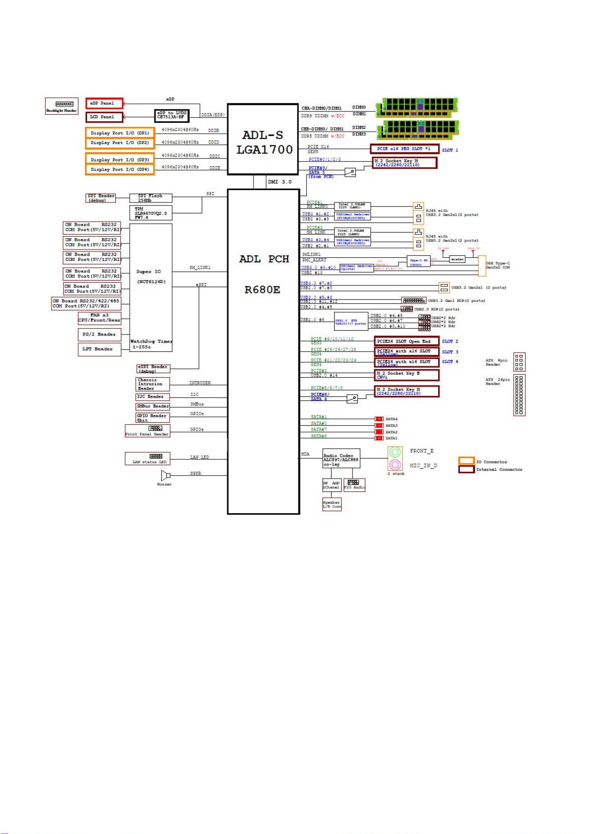
Block Diagram

RX680R User’s Manual
14
Product
Introduction
This chapter describes the
motherboard features and the
new technologies it supports.
1
RX680R User’s Manual
15
1.1 Before you Proceed
Take note of the following precautions before you install motherboard components or
change any motherboard settings.
⚫Unplug the power cord from the wall socket before touching any
component.
⚫Use a grounded wrist strap or touch a safely grounded object or
a metal object, such as the power supply case, before handling
components to avoid damaging them due to static electricity
⚫Hold components by the edges to avoid touching the ICs on
them.
⚫Whenever you uninstall any component, place it on a grounded
anti-static pad or in the bag that came with the component.
⚫Before you install or remove any component, ensure that the
ATX power supply is switched off or the power cord is detached
from the power supply. Failure to do so may cause severe
damage to the motherboard, peripherals, and/or components.
1.2 Motherboard Overview
Before you install the motherboard, study the configuration of your chassis to ensure that the
motherboard fits into it. Refer to the chassis documentation before installing the
motherboard.
Make sure to unplug the power cord before installing or removing the
motherboard. Failure to do so can cause you physical injury and
damage motherboard components.
1.2.1 Placement Direction
When installing the motherboard, make sure that you place it into the chassis in the correct
orientation. The edge with external ports goes to the rear part of the chassis as indicated in
the image below.

RX680R User’s Manual
16
1.2.2 Screw Holes
Place eight (8) screws into the holes indicated by circles to secure the motherboard to the
chassis.
Do not over tighten the screws! Doing so can damage the
motherboard.
Place this side towards the rear of the chassis
RX680R User’s Manual
17
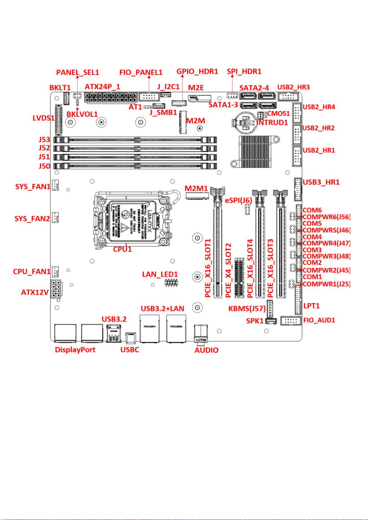
1.2.3 Motherboard Layout

RX680R User’s Manual
18
1.2.4 Layout Content List
Slots & Sockets
Print Name
Function
Note
CPU1
LGA 1700 Socket
J50~J53
DDR5 UDIMM Slots
Dual channel (2DPC)
PCIE_X16_SLOT1
Gen 5 PCIe
x16 Physical Black (Slot1)
PCIE_X4_SLOT2
Gen 3 PCIe
x4 Open Ended (Slot 2)
PCIE_X16_SLOT4
Gen 4 PCIe
x4 (x16 Physical Yellow) (Slot 4)
PCIE_X16_SLOT3
Gen 4 PCIe
x4 (x16 Physical Yellow) (Slot 3)
M2M1
Gen 4 PCIe x4 + SATA III
M Key
M2M
Gen 3 PCIe x4 + SATA III
M Key
M2E
PCIe x 1 + USB 2.0 support
CNVi
E Key
Jumper
Print Name
Function
Note
PANEL_SEL1
LVDS Panel Power Select
2x3 header, pitch 2.54mm
BKLVOL1
LVDS Blacklight Control
1x3 header, pitch 2.00mm
AT1
AT/ATX Mode Select
1x3 header, pitch 2.54mm
CMOS1
Clear CMOS
1x3 header, pitch 2.00mm
J56,J45~J48,J25
COM1~COM6 Power Setting
2x3 header, pitch 2.54mm
Rear I/O Connectors
Print Name
Function
Note
DisplayPort
DisplayPort Connectors x4
USB3.2
USB 3.2 Type A Connectors x2
USBC
USB 3.2 Type C Connector x1
USB3.2+LAN
RJ45 Ethernet Connectors x2
2.5 Gigabit Ethernet
USB 3.2 Type A Connectors x4
AUDIO
Audio Phone Jack
Lin-out, Mic-in

RX680R User’s Manual
19
Internal I/O Connectors
Print Name
Function
Note
CPU_FAN1
CPU FAN Connector
WAFER 1x4, 2.54mm
SYS_FAN1
Chassis Fan Connector
WAFER 1x4, 2.54mm
SYS_FAN2
Chassis Fan Connector
WAFER 1x4, 2.54mm
FIO_PANEL1
Front Panel Connector
BOX header 2x5P, 2.54mm
ATX24P_1
ATX Power Connector
PWR Conn 2x12P
ATX12V
12V ATX Power Connector
PWR Conn 2x4P
COM1~COM6
Serial Port Connectors
WAFER 2x5P, 2.00mm
SATA1~4
SATA Connectors
Male Connectors (RED)
USB2_HR1~4
Front USB 2.0 Headers
BOX header 2x5P, 2.54mm
USB3_HR1
Front USB 3.2 Header
BOX header 2x10P, 2.00mm
FIO_AUD1
Front Audio Connector
BOX header 2x5P, 2.54mm
SPK1
Amplifier Connector
WAFER 1x4P, 2.00mm
LVDS1
LVDS signals connector
Con. 2x20P, 1.25mm
INTRUD1
Chassis Intrusion Header
WAFER 1x2P, 2.54mm
LAN_LED1
LAN LED Header
2x5 header, 2.54mm
BKLT1
LVDS Backlight Control header
WAFER 1x5P, 2.00mm
LPT1
Parallel Port Connector
WAFER 2x13P, 2.0mm
GPIO_HDR1
GPIO 8 bits Connector
WAFER 2x6P, 2.00mm
J_I2C1
I2C Connector
WAFER 1x4P, 2.00mm
J_SMB1
SMBUS Connector
WAFER 1x5P, 2.00mm
SPI_HDR1
SPI Header
2x4 header, 2.54mm
J6
eSPI Header
2x5 header, 2.00mm
J57
KBMS Header
WAFER 1x 6P, 2.54mm

RX680R User’s Manual
20
1.3 Central Processing Unit (CPU)
The motherboard comes with a surface mount LGA1700 socket designed for the Intel®
Core™ i9/ i7/ i5/ i3 processor in the 1700-land package.
⚫Your boxed Intel® Core™ i9/ i7/ i5/ i3 LGA1700 processor
package should come with installation instructions for the CPU,
fan and heatsink assembly. If the instructions in this section do not
match the CPU documentation, follow the latter.
⚫Upon purchase of the motherboard, make sure that the PnP cap
is on the socket and the socket pins are not bent. Contact your
retailer immediately if the PnP cap is missing, or if you see any
damage to the PnP cap/socket pins/motherboard components.
BCM will shoulder the cost of repair only if the damage is
shipment/transit-related.
⚫Keep the cap after installing the motherboard. BCM will process
Return Merchandise Authorization (RMA) requests only if the
motherboard comes with the cap on the LGA1700 socket.
⚫The product warranty does not cover damage to the socket pins
resulting from incorrect CPU installation/removal, or
misplacement/loss/incorrect removal of the PnP cap.
⚫Install the CPU fan and heatsink assembly before you install
motherboard to the chassis.
If you purchased a separate CPU heatsink and fan assembly, make
sure that you have properly applied Thermal Interface Material to the
CPU heatsink or CPU before you install the heatsink and fan
assembly.
Table of contents
Other BCM Motherboard manuals


