Trikdis GV17 User manual

www.trikdis.com UAB Trikdis Draugystės str. 17, LT-51229 Kaunas, Lithuania +370 37 408 040 inf[email protected]
GSM gate controller GV17
Installation manual
November 2018

www.trikdis.com 2 November, 2018
GSM gate controller GV17
Contents
SAFETY PRECAUTIONS ........................................................................................................................ 3
1 DESCRIPTION .................................................................................................................................. 4
1.1 SPECIFICATIONS ...................................................................................................................................... 5
1.2 CONTROLLER ELEMENTS ........................................................................................................................... 5
1.3 PURPOSE OF TERMINALS .......................................................................................................................... 6
1.4 LED INDICATION OF OPERATION ................................................................................................................ 6
1.5 GSM GATE CONTROLLER GV17 STANDARD PACKING LIST ............................................................................... 7
2 WIRING SCHEMATICS FOR THE GSM GATE CONTROLLER GV17 ......................................................... 7
2.1 FASTENING ............................................................................................................................................ 7
2.2 SCHEMATIC FOR CONNECTING THE POWER SUPPLY ......................................................................................... 8
2.3 SCHEMATICS FOR CONNECTING INPUTS ........................................................................................................ 8
2.4 SCHEMATIC FOR CONNECTING THE RELAY ..................................................................................................... 8
3 QUICK SET UP OF THE CONTROLLER ................................................................................................. 9
4 REMOTE CONTROL .......................................................................................................................... 9
4.1 CONTROL WITH PHONE CALL ..................................................................................................................... 9
4.2 CONTROL WITH PHONE KEYBOARD.............................................................................................................. 9
4.3 CONTROL USING PROTEGUS CLOUD .......................................................................................................... 10
4.4 CONTROL WITH SMS MESSAGES .............................................................................................................. 12
4.5 CONFIGURATION WITH SMS MESSAGES .................................................................................................... 13
5 SETTING PARAMETERS USING TRIKDISCONFIG SOFTWARE .............................................................. 15
5.1 TRIKDISCONFIG STATUS BAR .................................................................................................................... 16
5.2 “SYSTEM OPTIONS” WINDOW ................................................................................................................. 16
5.3 “IN/OUT” WINDOW ............................................................................................................................ 17
5.4 “IP REPORTING” WINDOW ..................................................................................................................... 18
5.5 “USER LIST” WINDOW ........................................................................................................................... 19
5.6 “EVENTS LOG” WINDOW........................................................................................................................ 21
5.7 RESTORE DEFAULT SETTINGS ................................................................................................................... 22
6 SETTING PARAMETERS REMOTELY ................................................................................................. 22
7 TESTING OF GSM GATE CONTROLLER GV17 .................................................................................... 22
8 UPDATING FIRMWARE MANUALLY................................................................................................. 23

www.trikdis.com 3 November, 2018
GSM gate controller GV17
Safety precautions
The GSM gate controller should only be installed and maintained by qualified personnel.
Please read this manual carefully prior to installation in order to avoid mistakes that can lead to
malfunction or even damage to the equipment.
Always disconnect the power supply before making any electrical connections.
Any changes, modifications or repairs not authorized by the manufacturer shall render the warranty void.
Please adhere to your local waste sorting regulations and do not dispose of this equipment or its
components with other household waste.

www.trikdis.com 4 November, 2018
GSM gate controller GV17
1 Description
GSM gate controller GV17 can remotely control automatic gates and other equipment.
Users can control GV17 with Protegus application, telephone calls and SMS messages. The controller can
recognize up to 7 administrator and 990 user telephone numbers. A user control schedule and counter for
how many times a specific user can control the system can be set for the GV17. The GSM controller can
send SMS messages informing when inputs and outputs are activated and restored (the text of the SMS
messages is customizable). The controller is capable of sending event messages to the receiver of a security
company.
Features
Remote control
With Mobile/Internet application Protegus.
With SMS messages.
With phone call.
Messages for users
Sends messages about events to the
Protegus application or with text SMS
messages.
Messages for the safety company
Sends event information in Contact ID codes
to TRIKDIS software and hardware receivers,
which work with any monitoring software.
Can simultaneously send event messages to
the receiver of the safety company and work
with the Protegus app.
If connection with the main receiver is lost,
the messages are automatically sent to a
backup receiver.
Inputs and outputs
2 inputs (IN), of selectable type: NO; NC;
EOL.
2 universal inputs/outputs. Mode of
operation is set as either input or output.
1 output (OUT) - relay.
Settings and installation
Quick and easy installation.
Addition of new users and deletion of
existing users can be done with the Protegus
app (when logged in with administrator
rights), SMS message, TrikdisConfig
software.
Device can be configured either by
connecting a USB Mini-B cable or remotely
with the TrikdisConfig software.
Remote updating of firmware.
Two access levels for configuring the device,
for the installer and for the administrator.

www.trikdis.com 5 November, 2018
GSM gate controller GV17
1.1 Specifications
Parameter Description
2G GSM modem frequencies 850 / 900 / 1800 / 1900 MHz
3G UMTS modem frequencies 800 / 850 / 900 / 1900 / 2100 MHz
Power supply voltage 9-32 V DC
12-24 V AC
Current consumption 100 mA
Inputs 2, selectable type: NC, NO, EOL=10 kΩ
Universal inputs/outputs 2, can be set either as input IN with type: NC, NO, EOL=10 kΩ, or
output OUT (open collector (OC) 50 mA)
Output 1, relay, 1 A 30 V DC, 0,5 A 125 V AC
Unsent events memory Up to 60 events
Event log memory Up to 5000 events
Users who receive messages
and have permission to control
7
Users who have permission to
control
990
Operating environment Temperature from –20 °C to +50 °C, relative humidity – up to 80%
at +20 °C
Dimensions 92 x 62 x 26 mm
Weight 80 g
1.2 Controller elements
1. Light indicators.
2. Frontal case opening slot.
3. USB Mini-B port for controller programming.
4. Terminal for external connections.
5. Nano-SIM card slot.
6. GSM antenna SMA connector.

www.trikdis.com 6 November, 2018
GSM gate controller GV17
1.3 Purpose of terminals
Terminal Description
AC/+DC Power terminal (9-32 V DC positive; 12-24 V AC)
AC/-DC Power terminal (9-32 V DC negative; 12-24 V AC)
1 IN 1st input, of selectable type NO, NC, EOL (factory setting: NO)
2 IN 2nd input, of selectable type NO, NC, EOL (factory setting: NO)
COM Common terminal
3 I/O Input/output (factory setting: type OC output)
4 I/O Input/output (factory setting: type OC output)
NC Relay terminal NC
C Relay terminal C
NO Relay terminal NO
A RS485 Contact A of RS485 bus
B RS485 Contact B of RS485 bus
1.4 LED indication of operation
Indicator Light status Description
NETWORK Green solid Connected to GSM network
Yellow blinking Indication of GSM signal strength from 0 to 5. Sufficient
strength is 3.
DATA Green solid Message is being sent
Yellow solid There are unsent event messages in the data buffer
POWER Green blinking The power supply voltage is sufficient
Yellow blinking The power supply voltage is insufficient
Red and yellow
blinking
Configuration mode is on
TROUBLE Off No operation problems
1 blink No SIM card inserted
2 blinks The PIN code of the SIM card is incorrect
3 blinks Unable to connect to GSM network
4 blinks Unable to connect to Protegus or to the primary IP receiver
5 blinks Unable to connect to the backup IP receiver
6 blinks Internal clock is not set
7 blinks The power supply voltage is insufficient

www.trikdis.com 7 November, 2018
GSM gate controller GV17
If the LED indication is not working, check the power supply and connections.
Note: Before beginning installation, make sure that you have the necessary components:
1) USB Mini-B type cable for configuration.
2) Cable consisting of at least 4 wires for connecting the controller.
3) Flat-head 2,5 mm screwdriver.
4) External GSM antenna if reception is weak in the area.
5) Activated nano-SIM card (can have turn off PIN code requests).
6) Instruction manual for the automatic gate to which the GSM gate controller is about
to be connected.
Order the necessary components separately from your local retailer.
1.5 GSM gate controller GV17 standard packing list
-
GSM gate controller GV17 1 pc.
-
GSM antenna 1 pc.
-
Resistor 10 kΩ 3 pcs.
-
Double-sided adhesive tape (5 cm) 1 pc.
-
Screw 2 pcs.
2 Wiring schematics for the GSM gate controller GV17
2.1 Fastening
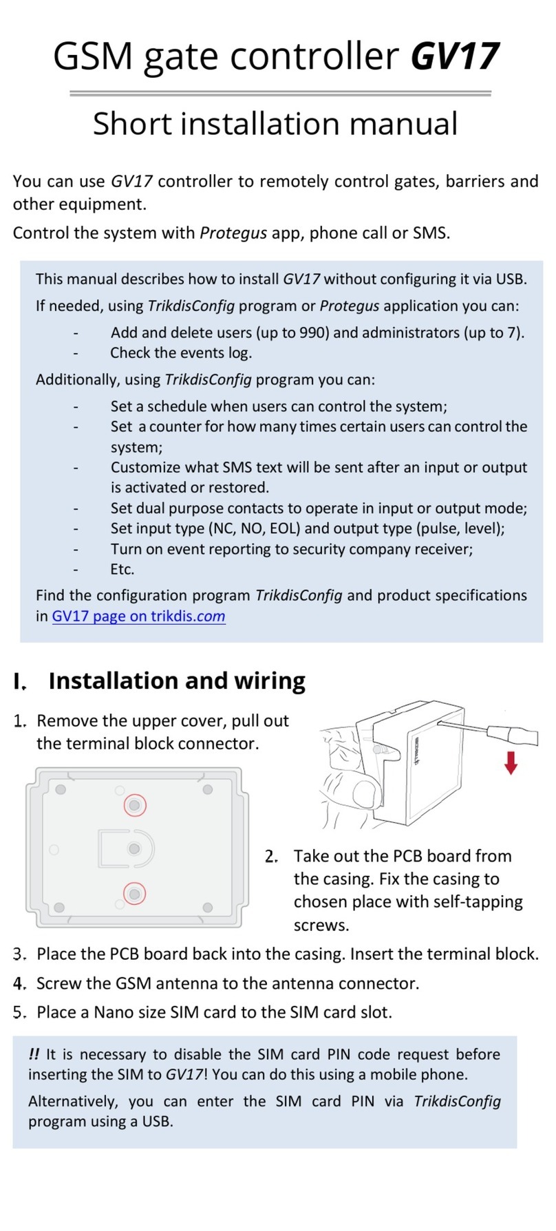
1. Remove the top lid. Pull out the plug
part of the terminal block.
2. Remove the PCB board.
3. Fasten the base of the case in the
desired place using screws.
4. Reinsert the board and the terminal
block.
5. Screw the GSM antenna in.
6. Insert the nano-SIM card.
7. Close the top lid.

www.trikdis.com 8 November, 2018
GSM gate controller GV17
2.2 Schematic for connecting the power supply
Using wires, connect the GV17 controller according to the schematic shown below.
2.3 Schematics for connecting inputs
The GV17 has four inputs IN (two of which are universal and can operate either as inputs or outputs) for
the connection of various alarm sensors. These inputs can operate in NC, NO, EOL modes. Connect the
inputs according to the set input type (NC, NO, EOL) as is shown in the schematics bellow:
2.4 Schematic for connecting the relay
Above is the schematic for connecting the relay when the GV17 is connected to a DC power source. Using
the terminals of the relay, it is possible to remotely control (turn on/off) various electric devices.

www.trikdis.com 9 November, 2018
GSM gate controller GV17
3 Quick set up of the controller
Note: The controller comes factory pre-configured to work. A call from any phone to controller’s
SIM card number will turn on the 5 OUT relay output for 3 (three) seconds. The controller can
be installed without any additional configuration if such operation mode is acceptable.
1. A nano-SIM card must be inserted into the GV17. Turn off PIN code requests for the card before
inserting it into the controller.
2. Connect a power source to the GV17 (see 2 “Wiring schematics for the GSM gate controller GV17 ”).
3. Turn on the power for the controller. This should trigger the following GV17 LED indications:
The “Power” indicator should blink green;
The “Network” indicator should be green solid and blink yellow.
The default settings allow control by anyone who calls the phone number of the SIM card inserted into the
controller.
If you want to allow only particular people to control the controller, send an SMS command with user
phone numbers, who are authorized (example SMS command: SETU 123456 +370xxxxxxxx#Peter).
After receiving such command, GV17 will react only to the phone numbers on the list. The controller will
ignore incoming phone calls from other numbers.
Note: If you wish to alter the default settings or turn on other functions of the controller, refer to
chapter 5 „Setting of parameters using TrikdisConfig software“.
4 Remote control
4.1 Control with phone call
Call the number of the SIM card inserted into the controller. The controller automatically rejects the call
and turns on the 5 OUT relay output for 3 (three) seconds. Default settings allow anyone who calls the
number of the SIM card inserted into the controller to control.
4.2 Control with phone keyboard
GV17 answers and allows to control the outputs with a phone call the user is allowed to control several
outputs OUT:
1. Call the controller’s SIM card number. The controller will accept the call.
2. Using the phone keyboard, dial the control command (command examples can be found in the table
DTMF control commands).
Note: The first one to call (or send an SMS to) the controller will become the system administrator
and will be the only one who can administer and control the controller with SMS commands.

www.trikdis.com 10 November, 2018
GSM gate controller GV17
DTMF control commands
DTMF code Function Description
OUTPUT*STATE# Output
control
Output control command (turn on/turn off; turn on/turn off for
pulse time).
OUTPUT – number of the controlled output.
STATE – control command:
0 – turn off output;
1 – turn on output;
2 – turn off output for pulse time;
3 – turn on output for pulse time;
(output pulse time can be set using the TrikdisConfig program, in
the Input/Output settings table)
# - control command end symbol.
E.g. (turn on output 5): 5*1#
E.g. (turn on input 4 for pulse time): 4*3#
# Command
end symbol
If you made a mistake writing a command, dial # and enter the
control command again.
4.3 Control using Protegus cloud
With Protegus users will be able to control GV17 remotely. They will also be able to see the system state
and receive all system event messages.
1. Download and launch the Protegus app or use the browser version of Protegus at
www.protegus.eu/login.
2. Log in with your user name and password or register and create a new account.
3. Choose Add new system and enter the GV17 Unique ID (IMEI) number found on the product or on
the packaging sticker.
IMPORTANT:
When adding the GV17 to Protegus:
1. The Protegus service must be turned on. Turning on the service is described in
chapter 5.4 Window “IP reporting”;
2. The power supply must be turned on („POWER“ LED must blink green);

www.trikdis.com 11 November, 2018
GSM gate controller GV17
3. Must be registered in to network („NETWORK“ LED must be green solid and blink
yellow).
4. After adding the GV17 to Protegus choose Control in the newly opened window.
5. In the opened window are the PGM control buttons. In the PGM control button settings choose either
Level or Pulse output operation mode.
6. After clicking on a PGM button, the GV17 output is turned on. (Example: PGM3 – output turned off;
PGM4 – output turned on, the PGM operation mode Level is set; PGM5 – output turned on, the PGM
operation mode Pulse is set)

www.trikdis.com 12 November, 2018
GSM gate controller GV17
4.4 Control with SMS messages
Control the relay output OUT5 with these SMS commands:
OUTPUT5 xxxxxx ON
OUTPUT5 xxxxxx OFF
OUTPUT5 xxxxxx PULSE=002
xxxxxx 6-symbol administrator password. (default code – 123456).
ON Turn on output.
OFF Turn off output.
PULSE=ttt Turn on output for a specified time. “ttt” is pulse time in seconds.
You can control other outputs with SMS, but first they need to be turned on in TrikdisConfig.
SMS control command list
Command Data Description
OUTPUTx ON Turn on output. “x” – output number.
E.g.: OUTPUT5 123456 ON
OFF Turn off output. “x” – output number.
E.g.: OUTPUT5 123456 OFF
PULSE=ttt Turn on output for a period of time. “ttt” is pulse time in
seconds, from 1 to 999.
E.g.: OUTPUT5 123456 PULSE=002

www.trikdis.com 13 November, 2018
GSM gate controller GV17
4.5 Configuration with SMS messages
1. Changing the administrator’s password
For safety reasons, change the default administrator password. Send an SMS message of this format:
PSW 123456 xxxxxx
123456 Default administrator password.
xxxxxx New 6-symbol administrator password.
2. Allow only authorized users to control the system
You can allow only specific people to control the system. From an administrator’s phone, send SMS
messages with the users’ phone numbers and names:
SETU xxxxxx +PHONENR#NAME
xxxxxx 6-symbol administrator password.
PHONENR User’s phone number.
NAME User’s name or e-mail.
Once the first number is added to the GV17’s user phone list, the controller will react only to phone calls
from the numbers on the list. The controller will ignore calls from other numbers.
3. Give administrator rights to another user
You can give administrator rights to other people. They will receive system information messages and will
be able to add users. Send an SMS message of this format:
SETA xxxxxx Nrx=+PHONENR#NAME
xxxxxx 6-symbol administrator password.
Nrx x – administrator’s number in the list. (If you write 1, you will transfer your
administrator rights to another user.)
PHONENR User’s phone number.
NAME User’s name or e-mail.
SMS configuration command list
Command Data Description
INFO Request information about the controller. The response will
include: controller type, IMEI number, GSM signal strength,
power voltage magnitude, software version, serial number,
date and time. E.g.: INFO 123456
ASKI Input status inquiry. E.g.: ASKI 123456
ASKO Output status inquiry. E.g.: ASKO 123456
SETA NrX=phonenr#name Add administrator to list. Adds the phone number and name to
the specified line. The number must be separated from the
name with a hash (#). The number must start with + and the
international code.
E.g.: SETA 123456 Nr3=+37061234567#John
NrX=DEL Deletes phone number and name from the specified line.
E.g.: SETA 123456 Nr2=DEL

www.trikdis.com 14 November, 2018
GSM gate controller GV17
Command Data Description
SETU phonenr#name Add new user. Adds the phone number and name to the list. The
number must be separated from the name with a hash (#). The
number must start with + and the international code.
E.g.: SETU 123456 +37061234567#Peter
DELU phonenr Delete user with specified phone number.
E.g.: DELU 123456 +37061234567
name Delete user with specified name. E.g.: DELU 123456 Peter
SETB Email/phoneNo Add entry into black-list (e-mail; phone No.).
Pvz.: SETB 123456 VardaS@mail.lt
Pvz.: SETB 123456 +37060123456
DELB ALL Delete all black-list. E.g.: DELB 123456 ALL
Email/phoneNo Delete a particular entry from the black list (for e-mail field small
and capital letters are important).
E.g.: DELB 123456 VardaS@mail.lt
E.g.: DELB 123456 +37060123456
RESET Restart the controller. E.g.: RESET 123456
PSW New password Change password. E.g.: PSW 123456 654123
TXTA Object name Set object name. E.g.: TXTA 123456 House
TXTE N1=<TEXT>
……
N5=<TEXT>
Set SMS text about input or output activation. N1…N5 is the
number of the contact on the terminal block.
E.g.: TXTE 123456 N1=Alarm in the living room
TXTR N1=<TEXT>
……
N5=<TEXT>
Set SMS text about input or output recovery. N1…N5 is the
number of the contact on the terminal block.
E.g.: TXTR 123456 N5=Relay turn offd
SETD IDx=yy Set inactivity time for input “x”. “yy” is inactivity time in
minutes, from 0 to 2880. When the input is activated, the
controller will send a notification and will not react to any
further circuit disruptions during the set inactivity time. If 0 is
entered, inactivity will be turn offd. E.g.: SETD 123456 ID1=30
RESD IDx Resets inactivity time for input “x”, if the countdown has
started. E.g.: RESD 123456 ID1
TIME YYYY/MM/DD,
HH:mm:ss
Set date and time.
E.g.: TIME 123456 2018/01/03,12:23:00
RDR PhoneNR#SMStext Forwards the SMS text to the specified number.
E.g.: RDR 123456 +37061234567#Refill account by 10EUR
UUSD *UUSD code# Sends UUSD code to mobile operator. Operator specified UUSD
codes are for checking or refilling the SIM card’s balance and for
similar operations. E.g.: UUSD 123456 *245#

www.trikdis.com 15 November, 2018
GSM gate controller GV17
Command Data Description
CONNECT Protegus=ON Connect to Protegus cloud.
E.g.: CONNECT 123456 PROTEGUS=ON
Protegus=OFF Disconnect from Protegus cloud.
E.g.: CONNECT 123456 PROTEGUS=OFF
APN=Internet APN name. E.g.: CONNECT 123456 APN=INTERNET
USER=user APN user. E.g.: CONNECT 123456 USER=User
PSW=password APN password. E.g.: CONNECT 123456 PSW=password
Code=password Change Protegus Cloud login password.
E.g.: CONNECT 123456 Code=123456
5 Setting parameters using TrikdisConfig software
With TrikdisConfig you can change the GV17 controller’s settings (if default settings are not enough)
according to the program window descriptions below.
1. Download the configuration software TrikdisConfig from www.trikdis.com/lt/ (enter “TrikdisConfig”
in the search field) and install it.
2. Using a flat-head screwdriver, remove the GV17’s lid as shown below:
3. Connect the GV17 to a computer using a USB Mini-B cable.
4. Launch the configuration software TrikdisConfig. The program will automatically recognize the
connected device and will automatically open the GV17 configuration window.
5. Click Read [F4] to see current GV17 parameters. If prompted, enter administrator’s or installer’s code
in the pop-up window.
Note: The button Read [F4] will make the program read and show the settings currently saved on
the device.
The button Write [F5] will save the settings made in the program to the device.
The button Save [F9] will save the settings into a configuration file. You can upload the saved
settings to other devices later. This allows to quickly configure multiple devices with the same
settings.
The button Open [F8] will allow to choose a configuration file and open saved settings.
If you want to revert to default settings, click on the Restore button at the bottom left of the
window.

www.trikdis.com 16 November, 2018
GSM gate controller GV17
5.1 TrikdisConfig status bar
After connecting the GV17 to the TrikdisConfig software, the software will show information about the
connected device in the status bar:
Name Description
IMEI/Unique ID The device’s IMEI number
State Operational state
Device Device type (must show GV17)
SN Device’s serial number
BL Launcher version
FW Device’s firmware version
HW Device’s hardware version
State Type of connection with the software (with USB or remote)
Administrator Access level (shown after access code is approved)
When the button Read [F4] is clicked, the program will read and show the settings currently saved on the
GV17. With TrikdisConfig, adjust the required settings according to the program window descriptions
below.
5.2 “System Options” window

www.trikdis.com 17 November, 2018
GSM gate controller GV17
Settings group “General”
Object ID – enter account number (4 symbol hexadecimal number, 0-9, A-F), provided by the alarm
receiving center.
Object name – every event will be sent with the object name.
Time synchronization – choose a source for setting the time.
Administrator Code – with this code it is possible to change all of the parameters of the controller.
SMS language – SMS messages are sent with the symbols of the chosen language.
Hang-up after – the controller declines the call after the specified time.
Settings group “Periodic test”
Test Enable – if the box is ticked, periodic test messages are enabled.
Test period – setting of test sending time period.
Start test at – setting of test start time.
Test SMS text – enter the test SMS message text.
To Protegus Cloud – if the box is ticked, the test message will be sent to Protegus.
Settings group “SIM”
SIM card PIN – enter the PIN code of the SIM card.
APN – enter APN name.
Login – if required, enter user name.
Password – if required, enter password.
5.3 “IN/OUT” window
“IN/OUT” tab
Terminal – controller’s input and output terminal numbers
Function – terminal type (input, output, turned off).
SMS event text – enter SMS message event text.
SMS restore text – enter SMS message text for when terminal is restored.
Type – specify input type (NC, NO, EOL=10kΩ).
Inactive –input will be inactive for specified time after first activation. Enter 0 if you want to turn this
function off.
ARC – if box is ticked, the message will be sent to ARC (Alarm Response Center) and to Protegus.
No rest. – do not send restore event.

www.trikdis.com 18 November, 2018
GSM gate controller GV17
Pulse time – time for which the output is turned on, when output is set as Pulse type.
Sched – assign a schedule number for controlling the output.
Assign IN – assign input (IN) to output to see the actual state of the device depending on the input’s
state.
“Scheduler” tab
Enable – enable the time schedule for when the controller will control the output.
Start time – specify the time and days of the week from when the output will be turned on.
End time – specify the time and days of the week until when the output will be turned on.
5.4 “IP Reporting” window
Settings group “Primary channel”
Communication type – choose the type of communication (IP, SMS) with the ARC (Alarm Receiving
Center) receiver.
Domain or IP – enter the receiver’s domain or IP address.
Port – enter the receiver’s network port number.

www.trikdis.com 19 November, 2018
GSM gate controller GV17
Tel number – phone number of ARC receiver capable of receiving SMS messages (e.g.: 370xxxxxxxx),
when selected Communication type is SMS.
Encryption Key – 6-digit message encryption key that must match the encryption key of the ARC
receiver.
Settings group “Backup channel”
The settings are identical to those of the main communication channel.
Settings group “Settings”
Return to primary after – time period after which the controller will attempt to regain connection
with the primary channel.
IP Ping period – enable sending of PING signal and set the length of its period.
SMS Ping period – enable sending of PING signal and set the length of its period.
Backup reporting after – specify amount of attempts to connect with the main channel, after which
the controller will automatically connect to the backup connection channel.
DNS1 and DNS2 – IP addresses of DNS servers.
Settings group “Backup channel 2”
Tel number - phone number of ARC receiver capable of receiving SMS messages (e.g.: 370xxxxxxxx).
The backup SMS channel is used when messages fail to send with both primary and backup channels.
It is extremely useful because it functions even when IP connectivity is disrupted in the mobile
operator’s network. This channel works only when GPRS mode is set both for the main channel and
backup channel. SMS messages will be sent to the response center’s SMS receiver: 1) as soon as the
GV17 is enabled for the first time; 2) after loss of TCP/IP or UDP/IP connection in the main and backup
channels.
Settings group “PROTEGUS cloud”
Enable connection – enable Protegus service, the GV17 will be able to exchange data with the
Protegus app and also remote configuration with TrikdisConfig will be possible.
Parallel reporting – the messages are sent simultaneously to the ARC, Protegus and to users. When
not enabled, messages to Protegus and users will be sent only after being sent to ARC.
Protegus Cloud Code – 6-digit code for connecting with Protegus (default code - 123456).
5.5 “User list” window
“Administrators” tab

www.trikdis.com 20 November, 2018
GSM gate controller GV17
Name/E-mail – specify administrator’s name or e-mail address.
Tel number – specify administrator’s phone number (e.g.: +370xxxxxxxx).
Control – specify the outputs that the administrator will control.
SMS notification – specify events (IN1, IN2, OUT3, OUT4, OUT5) that the administrator will receive
SMS notifications about.
Test – administrator will receive test messages.
ACK – administrator will get answer SMS messages when they control and configure the controller
with SMS messages.
FWD – SMS message forwarding from unknown numbers.
“Users” tab
Name/E-mail – specify user’s name or e-mail address.
Tel number – specify user’s phone number (e.g.: +370xxxxxxxx).
En – if boxed is ticked, user is allowed to control outputs OUT.
Sched. – assign a schedule (specify a schedule number) for when the user can control outputs OUT.
Valid from – specify date and time from when the user can control the controller.
Valid until – specify date and time until when the user can control the controller.
Counter:
o En – enable counter.
o n – specify number of times that user can control the controller during the chosen time.
o e – current number of control times.
Outputs – specify output number that the user can control.
Note: If box En. Is unticked for user No.10 with the name Not authorized, users not on the users
list will be banned from controlling the controller with phone call.
Other manuals for GV17
1
Table of contents
Other Trikdis Controllers manuals
