Trikdis T7 User manual

WIRELESS SECURITY SYSTEM
T7 transmitter
User’s manual

2
Contents
1. Technical reference
1.1 Application
1.2 Package components
1.3 Specifications
1.4 General view and layout of control devices
1.5 Features
1.6 Description of contacts
1.7 Indication
2. Exploitation instructions
2.1 Parameter programming
2.2 Default settings
2.3 Installation of the transmitter
2.4 Connection of the transmitter
2.5 Communication test and evaluation
Annexes
3
3
3
3
4
5
5
6
7
7
10
12
13
13
14

3
SAFETY REQUIREMENTS
Before using T7 transmitter read the following instructions and fulfill the
safety requirements.
T7 transmitter is a part of security system, working 24 hours non-stop.
The meanings of the T7 transmitter’s light-emitting indicators:
- Shining green – power supply is alive the transmitter operates.
- Shining red – the message is transmitting via wireless communication.
- Shining yellow – failed messages exist.
Users provided with security service, can’t come into contact or other way
affect the operation of the equipment.
Only trained personnel, who are aware of the operational principles of
transmitting devices, propagation of radio waves and safety requirements, may
perform the installation of the device and constant maintenance.
Necessary cases and power supply sources have to conform the safety
requirements according to the LST EN 60950 standard.
The transmitter operates together with internal antennas, built inside the
object being secured. Installing the transmitter into another equipment, and/or
using external antennas, the high-speed lighting over voltage protection devises,
the voltage of which not less than 350V, must be equipped in accordance with
the requirements provided by LST EN 60950 standard.
THE TRANSMITTER MUST BE RELIABLY GROUNDED! LIGHTNING
OVER-VOLTAGE SUPPRESSOR MUST BE EQUIPPED TO ANTENNA
CONNECTOR.

4
1. TECHNICAL REFERENCE
1.1 APPLICATION
T7 transmitter (further referred to as transmitter) is used for transmitting
messages in encoded digital form via wireless channel to the central monitoring station
in order to provide information about the state of secured object.
These instructions are applied for several versions of the transmitters:
- v7 (version Ver.RS5-4SRSEN.VHF.xxxxx)
- v7P (version Ver.RS5-4RSPEN.VHF.xxxxx)
- v7U (version Ver.RS5-4SRSEN.UHF.xxxxx)
- v7UP (version Ver.RS5-4RSPEN.UHF.xxxxx)
1.2 PACKAGE COMPONENTS
The package components of the T7 v7transmitter:
- Transmitter T7 v7 – 1unit.
- Resistor 2,2 kΩ– 6 units.
- Technical reference and user’s manual – 1unit.
The package components of the T7v7P transmitter:
- Transmitter T7v7P – 1 unit.
- Resistor 2,2 kΩ– 6 units.
- Cable for connection with serial interface of security control panel – 1 unit.
- Technical reference and user’s manual – 1unit.
1.3. SPECIFICATIONS
Table 1.
Parameter Characteristics
Radio engineering parameters
146 ... 174 MHzFrequency band: v7
V7U 430 ... 470 MHz
Communication channel spacing 12,5 kHz
Output resistance 50 Ω, for TNC connector
Enable frequency error, less than ±1000 Hz
Deviation, less than ± 1,5 kHz
Output power 4,5 W
Spurious emissions According to the requirements of EN 300 113
standard
Systematic parameters
Number of message codes 256
Number of information inputs 7 units
Type of information inputs NC, NO, EOL (2,2 kΩ)
Data transmitting report RAS-2M
Message formation levels from
internal voltage controller:
Too low voltage
Normal voltage
11,5 V
12,6 V
General parameters
Normal operating voltage 12,6 V
Operating voltage range 11 – 14 V
Current in operation:
During the transmitting, less than
In idle mode, less than
1,2 A
60 mA
Overall dimensions 140х69х22 mm
Mass, less than 0,2 kg
Range of temperatures From -20°C to +55°C
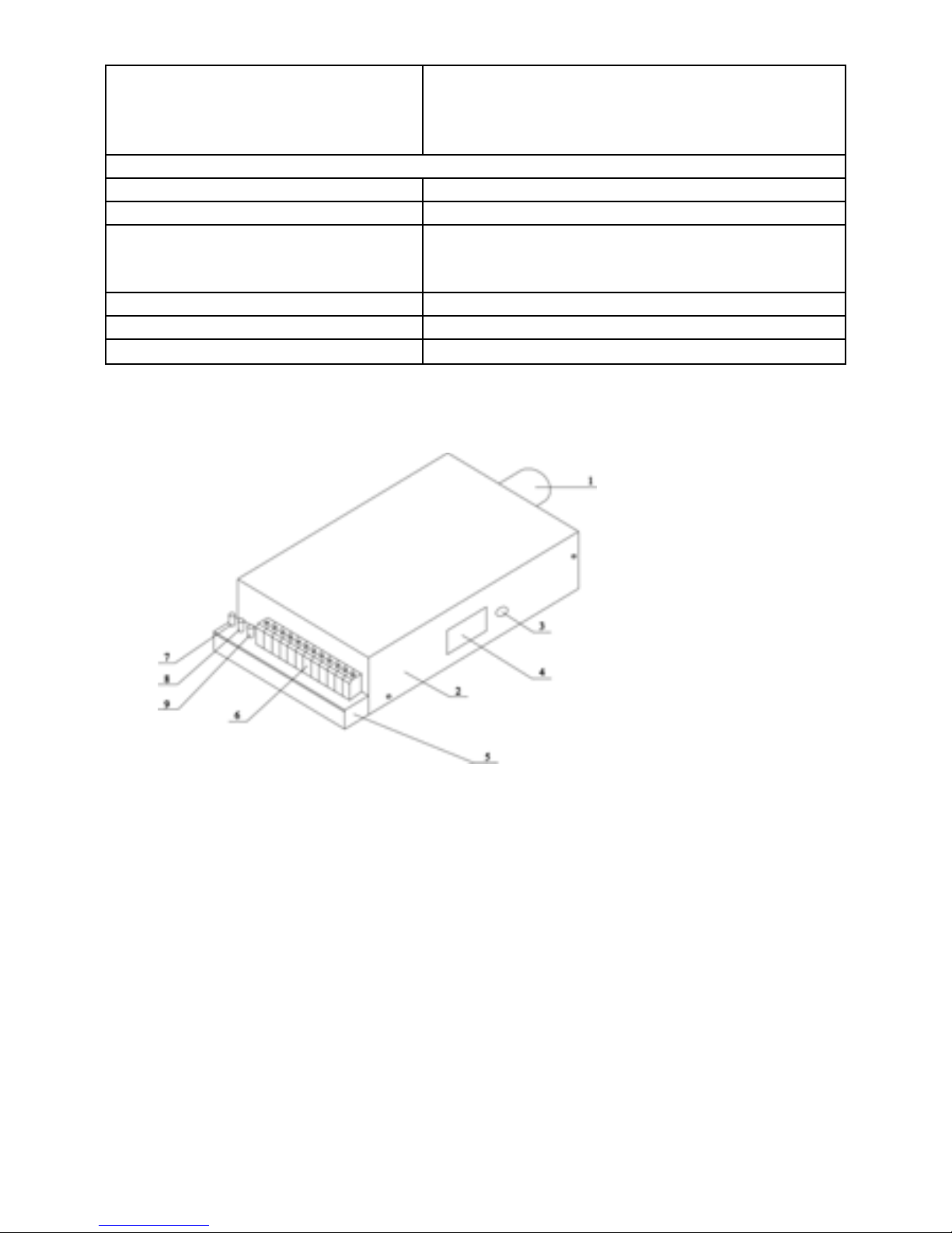
1.4 GENERAL VIEW AND LAYOUT OF CONTROL DEVICES
Fig.1 General view and control devices
1. Antenna connector (TNC);
2. Transmitter’s lid;
3. RESET button;
4. Connector of programming and interconnection with other devices;
5. Transmitter’s case;
6. Contacts of external inputs;
7. Voltage supply indicator (green);
8. Transmitting indicator (red);
9. Indicator of failed messages (yellow);
1.5 FEATURES
5

6
T7 transmitter has seven regularly controlled external inputs and internal
operating voltage controller. When mode of input changes the message is generated
and sent.
The transmitter has a serial interface available for programming of operating
parameters and for interchange of the data from external devices. The serial interface is
detected automatically, after the connection of external device, and it is activate until
this device is connected. The system sends the messages about connection and
disconnection of external device.
The serial interface of security control panels (such as Paradox Esprit plus, Esprit
Ultra and Spectra) may be connected to the serial interface of the transmitter. The
messages from security control panel are sent to the transmitter, modified according to
the system codes, and transferred to the central receiver. The list of unified codes is
given in the annex No 1.
When operating voltage changes and gets out of the determined range, the
system sends message to inform about these changes. When the operating voltage
drops (less than 10 V), the transmitter sends the “kiss off” message (252) and switches
on “sleep” mode, during which the messages are not sent, but other functions are
performed. After the operating voltage restores and the period of time set in
programming passes, the transmitter automatically turns back to normal mode and
sends the message “LOW BATTERY Restore”.
By programming in accordance with determinate periodicity, communication-
testing signals (tests) are sent.
The transmitting message includes: subscriber’s number, event code and
transmitter’s service information. The message is repeated for several times during a
single transmitting process. The periods between repetition changes according to
random law.
When transmitter’s parameters are programmed, the below mentioned data is
hold in its memory:
- Transmitter’s subscriber’s number (from 1 to 8191)
- Number of subsystem
- Input state codes
- The number of alarmed messages repetition
- The number of communication test repetition
- Periodicity of communication test
- Serial interface’s operation mode. (V7P)
Memory of the transmitter contains three copies of maintenance parameters.
Before sending the message these copies are compared and the message is sent. If
the copies are not coincident with each other, the error code (169) to show the possible
erroneousness is sent together.
1.6 Description of contacts

7
Fig.2 Layout of input contacts
1 C 2 3 C 4 5 C 6 8 +V K +E C
Contact Description
IN1 (1) Input 1
C Common wire
IN2 (2) Input 2
IN3 (3) Input 3
C Common wire
IN4 (4) Input 4
IN5 (5) Input 5
C Common wire
IN6 (6) Input 6
IN8 (8) Input 8
+V +12 V Commutate connecting contact
K Commutate connecting contact
+ E Power supply contact “+”
C Power supply contact “-”
The interface of programming and serial connection with other devices is on the
right side of the transmitter’s case near the RESET button.
1.7 INDICATION
The transmitter has three build-in indicators of light emitting diodes:
1. Shining yellow indicator informs that failed messages exist.
2. Shining red indicator indicates the mode of transmitting.
3. Shining green indicator indicates that the power supply is alive.
Red flickering light-emitting diode indicates troubles of the principal operating
program and message, which has been sent (169).
Alternative and slow flicker of red and yellow light-emitting diodes indicates that
the transmitter switches on the “sleep” mode.
When the transmitter from “sleep” mode returns back to the operating mode,
yellow light-emitting diode is active until the first message will be sent.
In programming mode red light emitting diode is active constantly.
2 Exploitation instructions

2.1 PARAMETER PROGRAMMING
Before installing the transmitter into the object being secured, the parameters
such as subscriber’s number, input alarm and restore codes, number of sent messages
repetition and periodicity of communication test repetition have to be programmed.
The process of programming is performed with PC by using a special cable for
interconnection its serial interface with the serial interface of the transmitter. The
standard Windows program “Hyper Terminal” is applied. Common Dialog Window
shows the menu and parameters of the transmitter. The keyboard is used to change the
appropriate value of the parameters.
In WINDOWS’ XX versions the program “Hyper terminal” is found according to
the following sequence of commands: Start/ Programs/ Accessories/ Communications/
Hyper terminal.
If the search of this program was unsuccessful, seek for the solution of this
problem in the computer service companies.
The steps of the transmitter’s programming process:
1. Couple the PC and the transmitter via special cable.
2. Activate the program “Hyper Terminal” and set the following options: the
speed of the data transmitting: 9600b/s, number of data bits: 8, Parity:
none, Stop bit: 1 and Flow control: none.
Those parameters can be saved into PC drive.
Fig.3 Setting of the parameters in “Hyper terminal” program.
3. Switch on the transmitter’s feeding and press the RESET button. If the
configuration is correct, red and green light emitting diodes are active and
the Dialog Window shows the version of the program and also the
command to enter password.
RS5.1-4SRPEN.VHF.xxxxx
SN ХХХХХХ
Password _
4. Entering [adm] [Enter] enables parameter programming.
The message for v7 version
8

9
Main Window
RS5-4SRSEN.VHF.xxxxx
SN XXXXXX
>1.ID
2.Repeat (1-9) times 3
3.Repeat Test (1-9) times 2
4.Test every (1-240) hours 24
5.Test after reset (1-240) hours 1
>6.Inputs
?
The number of the program;
The serial number of the transmitter;
The subscriber’s number of the transmitter;
The number of message repetition;
The number of communication tests;
The periodicity of communication tests (every 24
hours).
The first test after RESET pressing (1-24 hours.);
Switchover into the settings of input parameters.
The message for v7P version
Main Window:
RS5.1-4SRPEN.VHF.xxxxx
SN XXXXXX
>1.ID
2.Repeat (1-9) times 3
3.Repeat Test (1-9) times 2
4.Test every (1-240) hours 24
5.Test after reset (1-240) hours 1
>6.Inputs
>7.Paradox
?
The number of the program;
The serial number of the transmitter;
The subscriber’s number of the transmitter;
The number of message repetition;
The number of communication tests;
Periodicity of communication tests (every 24 hours).
The first test after RESET pressing
(1-24 hours.);
Switchover into the settings of input parameters.
Switchover into the settings of security central control
panel.
The parameters signed “>” have additional Dialog Windows to set an exact value,
those signed “*” can be switched on and off. Parameters are set using the keys from
the digital part of the keyboard. For example, to change the parameter No 3, the key [3]
should be pressed. If the appropriate value of the parameter is required, the note
[value] is displayed on the monitor. Below this note the appropriate value is entered
than pressing the key [Enter].
5. The subscriber’s number, the number of message repetition, periodicity of
communication test signals are entered from the Main Window. The appropriate input
type: NO, NC, EOL can be set from this Window as well. Select the appropriate input
and perform the changes by pressing the key of input number.
Time of vibration resistance contacts can be determined from this Window. After
pressing the key [S] you will see the list of inputs. Select appropriate input and change
the parameter, by entering necessary value. The parameter you enter is repeated for
the time of 20ms.
The mode of all input control [K] is assigned to a single input. Given error in such
input, all other inputs are controlled. The codes of false inputs or communication test
signals are transmitted to the central monitoring station. The time of transmitting the
next signal of communication test left unchanged in this case.
Table 3 presents additional methods to change operating parameters.

10
Table3
Letter Clarification
L Change of external input type NO/NC/EOL
S Time setting of vibration resistance contacts
K Setting of external input for initiation the control of other
inputs
R Setting of switching on “sleep” mode and restoring
I Setting of error message codes
N Restoration of programming of default message codes
P Password change according to displayed instructions
H Change of recalculation system HEX/DEC
(Used only in Window of message code’s setting)
6. The appropriate input, available for programming is selected from Input Menu and
proper configuration is selected from the Dialog Window of particular input.
Input Window:
The Window is selected by pressing 6
RS5.1-4SRPEN.VHF.xxxxx
SN XXXXXX
Inputs
0.Back
>1.Input No 1
>2.Input No 2
>3.Input No 3
>4.Input No 4
>5.Input No 5
>6.Input No 6
>7.Input No 7
>8.Input No 8
?
Back to Main Menu;
Input No 1 Configuration
Input No 2 Configuration
Input No 3 Configuration
Input No 4 Configuration
Input No 5 Configuration
Input No 6 Configuration
Input No 7 Configuration
Input No 8 Configuration
Set up a proper value of event codes and input operation mode. Event codes
may have any value, but it is recommended using the codes system. For example,
Input No1 is programmed thus: code 101 means error, code 201- restoration. Input
No2: code 102 – error, code 202 – restoration etc.
Input configuration Window:
Enter the Window by 1-8
RS5.1-4SRPEN.VHF.xxxxx
SN XXXXXX

11
Input No 1 - 8
0.Back
*1.Alarm enable
*2.Restore enable
3.Alarm value (0-255) 161
4.Restore value (0-255) 177
?
Back to the previous Window;
Input trouble message on /off.
Input restore message on. /off.
Input trouble code;
Input restore code;
Parameters No 1 and No 2 indicate mode of input operation:
When the function Alarm is on and trouble of such input exists, the message to
inform about this trouble will be sent.
When the function Restore is on, after the restoration of this input the restoration
message will be sent.
When both functions (Restore and Alarm) are on, the message is generated after
the input error as well as after its restoration.
Press [0] to return back to previous menu.
8. The type of the security control panel, which is used together with the transmitter,
may be selected form the Main Window. Press [7] and select the appropriate type of
security control panel. The codes received from the security control panel and sent
through the transmitter are introduced in the annex No 1. Receivers, manufactured by
different producers, differently output the information about received messages into
monitoring programs, thus one should be aware of the features of the equipment in
operation and software.
Configuration Window of security
control panel:
Enter pressing the key 7
S5.1-4SRPEN.VHF.xxxxx
SN XXXXXX
Paradox
0.Back
*1.Esprit enable
*2.Spektra disable
?
Back to the previous Window;
Messages of Esprit control panel
enable;
Messages of Spectra control panel
enable;
Note: using the transmitter with Paradox control panel the number of sent
messages repetition must be equal to1.
9.Press [9] to return back to the Main Menu.
10. Switch off power supply and programming cable.
2.2 Default settings
Default settings of the transmitter (table. No 4).

12
Major parameters:
ID (0-8191) 8191
System(0-3) 0
Repeat (1-9) times 3
Repeat Test (1-9) times 2
Test every (1-240) hours 24
Test after reset (1-240) hours 1
L
Input No 1 EOL
Input No 2 EOL
Input No 3 EOL
Input No 4 EOL
Input No 5 EOL
Input No 6 EOL
Input No 7 ---
Input No 8 EOL
S
Inputs delay time *20 msek (1 - 60000)
Input No 1 16
Input No 2 16
Input No 3 16
Input No 4 16
Input No 5 16
Input No 6 16
Input No 7 250
Input No 8 20
K
Input Control No 1 Disable
Input Control No 2 Disable
Input Control No 3 Disable
Input Control No 4 Disable
Input Control No 5 Disable
Input Control No 6 Disable
Input Control No 7 Disable
Input Control No 8 Disable
R
Inputs delay time *20 msek (1 - 60000)
Power off 500
Power on 300000
I

13
Error (0-255) 169
Interface error (0-255) 250
Interface find (0-255) 251
Power down (0-255) 252
Input No1
Alarm Disable
Restore Disable
Alarm value (0-255) 161
Restore value (0-255) 177
Input No2
Alarm Disable
Restore Disable
Alarm value (0-255) 162
Restore value (0-255) 178
Input No3
Alarm Disable
Restore Disable
Alarm value (0-255) 163
Restore value (0-255) 179
Input No4
Alarm Disable
Restore Disable
Alarm value (0-255) 164
Restore value (0-255) 180
Input No5
Alarm Disable
Restore Disable
Alarm value (0-255) 165
Restore value (0-255) 181
Input No6
Alarm Disable
Restore Disable
Alarm value (0-255) 166
Restore value (0-255) 182
Input No7
Alarm Enable
Restore Enable
Alarm value (0-255) 167
Restore value (0-255) 183
Input No8

14
Alarm Disable
Restore Disable
Alarm value (0-255) 168
Restore value (0-255) 184
Paradox
Esprit Enable
Spectra Disable
2.3 Installation of the transmitter
The transmitter is installed being in a metal case, which contains a transformer, a
power supply unit and standby accumulator. The installation in the case of control panel
and using supplementary decorative case is also possible. In such cases the reliability
of power supply and safety requirements should be ensured.
When the transmitter is installed in a separate metal case together with power
supply elements, instead of installing it in the case of control panel, the more reliable
communication is guaranteed.
Reliable communication is ensured when the antennas of the receiver (or
repeater) and the transmitter are in the range of direct visibility. Mounting antennas,
various obstacles such as ferroconcrete and metal constructions, should be avoided. It
is much better to mount the antennas near the windows. The height at which the
transmitting antenna is mounted also has a positive effect on the reliability of the
communication. If it is impossible to build the transmitter in the zone of reliable
communication, external antennas have to be used. In this case the transmitter is build
in a safe and convenient for the installation place and the antenna in a place, ensured
reliable communication.
The transmitter is coupled with the antenna via coaxial cable of low damping 50 Ω
wave resistance (RG58, RG213). Remember, that a long cable negatively affect the
quality of communication. Anyway, mounting the antenna, it is necessary to ensure
reliable high frequency contact and proper harmony of the communication between the
antenna and the transmitter.
2.4 Connection of the transmitter
For feeding the transmitter the transformer is applied, which has to conform the
following specifications: power - not less than 40 W, secondary winding voltage - 16-18
V, load current – 2 A. For standby power supply 12 V accumulator is applied, the
capacitance of which is not less than 7A/h.
It is recommended applying power source of MBV 12/2 type, which have a
function of alternating current control, or alternative MBI 12/2 sources having installed
additional relay. For the connection of power supply units it is recommended using
cables not longer than 1,5m., the cross section of which is less than 0,5mm.
Power may be supplied from the leads +BELL and AUX of control panel, if +Bell
lead ensures constant 12 V voltage when load current is 1,5 A. Power also may be
supplied from the accumulator of security control panel, if it does not overbalance the

15
whole system. If the object operated for a long time without alternating power supply
voltage and accumulator has been discharged, thus the time required to charge it fully
continues from 8 to 20 hours.
Because the schemes of different control panels vary, the power is applied from
the different leads of the control panel.
Appling transmitters with Paradox control panels; serial interfaces of the
transmitter and control panel are connected via special cable.
Appling Esprit Ultra control panels, the feeding to the transmitters comes from the
terminals of accumulator +BAT and control panel −AUX. With discharging of
accumulator communication troubles are not avoided because of insufficient power
supply voltage.
Appling Paradox Spectra control panels, the feeding to the transmitter comes
from +BELL and −AUX terminals. In this instance communication troubles because of
too low power supply voltage will be bypassed because the feeding from alternating
voltage network will be ensured.
After fixing the transmitter, perform all necessary connections, apply power
supply voltage and press RESET button. This moment starts the report of
communication test sending time.
When external devices are connected to the transmitter, standard connectors
and leads of these devices should be used. Variations of feasible transmitter’s
connection examples are given at the end of this manual (Annexes No 2-5).
2.5 Communication test and evaluation
After the installation of the transmitter reliability and quality of the communication
should be evaluated. To perform this operation it is necessary to activate the inputs,
which are connected to the system. The test shows, are the sent messages received
correctly. If the received messages are unfaithful, it is necessary to check the
connection and programming.
If central monitoring station receives incomplete number of messages, a place
the antenna is mounted should be changed.
It is the most convenient to check the communication quality according to
indications of received signal level from central receiver (the receiver RI-4010V enables
this). The receiver enables receive and identify messages got at zero level, but for
reliable communication the third level of received signal is required.

16
ANNEX No 1
Unified message codes
Code Messages Mark
DEC HEX In English Lietuviškai
0 00 Communication test Ryšio patikrinimas Tx
1 01 Tx
2 02 Tx
3 03 Tx
4 04 Tx
5 05 Tx
6 06 Tx
7 07 Tx
8 08 Tx
9 09
10 0A
11 0B
12 0C
13 0D
14 0E
15 0F
16 10
17 11 Alarm zone 1 Aliarmas zona 1
18 12 Alarm zone 2 Aliarmas zona 2
19 13 Alarm zone 3 Aliarmas zona 3
20 14 Alarm zone 4 Aliarmas zona 4
21 15 Alarm zone 5 Aliarmas zona 5
22 16 Alarm zone 6 Aliarmas zona 6
23 17 Alarm zone 7 Aliarmas zona 7
24 18 Alarm zone 8 Aliarmas zona 8
25 19 Alarm zone 9 Aliarmas zona 9
26 1A Alarm zone 10 Aliarmas zona 10
27 1B Alarm zone 11 Aliarmas zona 11
28 1C Alarm zone 12 Aliarmas zona 12
29 1D Alarm zone 13 Aliarmas zona 13
30 1E Alarm zone 14 Aliarmas zona 14
31 1F Alarm zone 15 Aliarmas zona 15
32 20 Alarm zone 16 Aliarmas zona 16
33 21 Alarm zone 17 Aliarmas zona 17
34 22 Alarm zone 18 Aliarmas zona 18
35 23 Alarm zone 19 Aliarmas zona 19
36 24 Alarm zone 20 Aliarmas zona 20
37 25 Alarm zone 21 Aliarmas zona 21
38 26 Alarm zone 22 Aliarmas zona 22
39 27 Alarm zone 23 Aliarmas zona 23
40 28 Alarm zone 24 Aliarmas zona 24
41 29 Alarm zone 25 Aliarmas zona 25

17
42 2A Alarm zone 26 Aliarmas zona 26
43 2B Alarm zone 27 Aliarmas zona 27
44 2C Alarm zone 28 Aliarmas zona 28
45 2D Alarm zone 29 Aliarmas zona 29
46 2E Alarm zone 30 Aliarmas zona 30
47 2F Alarm zone 31 Aliarmas zona 31
48 30 Alarm zone 32 Aliarmas zona 32
49 31
50 32
51 33
52 34
53 35
54 36
55 37
56 38
57 39
58 3A
59 3B I-st key, Auxiliary I-as mygtukas, medicina
60 3C II-st key, Panic II-as mygtukas, panika
61 3D III-st key, Fire III-as mygtukas, gaisras
62 3E Duress, Panic Prievarta, panika
63 3F Key restored Mygtukas atsistatė
64 40
65 41 Restore zone 1 Atsistatymas zona 1
66 42 Restore zone 2 Atsistatymas zona 2
67 43 Restore zone 3 Atsistatymas zona 3
68 44 Restore zone 4 Atsistatymas zona 4
69 45 Restore zone 5 Atsistatymas zona 5
70 46 Restore zone 6 Atsistatymas zona 6
71 47 Restore zone 7 Atsistatymas zona 7
72 48 Restore zone 8 Atsistatymas zona 8
73 49 Restore zone 9 Atsistatymas zona 9
74 4A Restore zone 10 Atsistatymas zona 10
75 4B Restore zone 11 Atsistatymas zona 11
76 4C Restore zone 12 Atsistatymas zona 12
77 4D Restore zone 13 Atsistatymas zona 13
78 4E Restore zone 14 Atsistatymas zona 14
79 4F Restore zone 15 Atsistatymas zona 15
80 50 Restore zone 16 Atsistatymas zona 16
81 51 Restore zone 17 Atsistatymas zona 17
82 52 Restore zone 18 Atsistatymas zona 18
83 53 Restore zone 19 Atsistatymas zona 19
84 54 Restore zone 20 Atsistatymas zona 20
85 55 Restore zone 21 Atsistatymas zona 21
86 56 Restore zone 22 Atsistatymas zona 22
87 57 Restore zone 23 Atsistatymas zona 23
88 58 Restore zone 24 Atsistatymas zona 24
89 59 Restore zone 25 Atsistatymas zona 25
90 5A Restore zone 26 Atsistatymas zona 26

18
91 5B Restore zone 27 Atsistatymas zona 27
92 5C Restore zone 28 Atsistatymas zona 28
93 5D Restore zone 29 Atsistatymas zona 29
94 5E Restore zone 30 Atsistatymas zona 30
95 5F Restore zone 31 Atsistatymas zona 31
96 60 Restore zone 32 Atsistatymas zona 32
97 61
98 62
99 63
100 64
101 65 Tx
102 66 Tx
103 67 Tx
104 68 Tx
105 69 Tx
106 6A Tx
107 6B Tx
108 6C Tx
109 6D
110 6E
111 6F
112 70 Arm Installer Įjungta instaliatoriaus kodu
113 71 Arm user 1 Įjungta kodu 1
114 72 Arm user 2 Įjungta kodu 2
115 73 Arm user 3 Įjungta kodu 3
116 74 Arm user 4 Įjungta kodu 4
117 75 Arm user 5 Įjungta kodu 5
118 76 Arm user 6 Įjungta kodu 6
119 77 Arm user 7 Įjungta kodu 7
120 78 Arm user 8 Įjungta kodu 8
121 79 Arm user 9 Įjungta kodu 9
122 7A Arm users 10-19 Įjungta kodu 10 - 19
123 7B Arm users 20-29 Įjungta kodu 20 - 29
124 7C Arm users 30-39 Įjungta kodu 30 - 39
125 7D Arm users 40-47 Įjungta kodu 40 - 47
126 7E Arm under duress Prievartinis įjungimas Kodas
48
127 7F Arm Master Įjungta Master kodu
128 80 Disarm Installer Išjungta instaliatoriaus
kodu
129 81 Disarm user 1 Išjungta kodu 1
130 82 Disarm user 2 Išjungta kodu 2
131 83 Disarm user 3 Išjungta kodu 3
132 84 Disarm user 4 Išjungta kodu 4
133 85 Disarm user 5 Išjungta kodu 5
134 86 Disarm user 6 Išjungta kodu 6
135 87 Disarm user 7 Išjungta kodu 7
136 88 Disarm user 8 Išjungta kodu 8
137 89 Disarm user 9 Išjungta kodu 9

19
138 8A Disarm users 10-19 Išjungta kodu 10 - 19
139 8B Disarm users 20-29 Išjungta kodu 20 - 29
140 8C Disarm users 30-39 Išjungta kodu 30 - 39
141 8D Disarm users 40-47 Išjungta kodu 40 - 47
142 8E Disarm under duress Prievartinis išjungimas Kodas
48
143 8F Disarm Master Išjungta Master kodu
144 90
145 91 Disarm 1 or 5 partition Išjungtos 1 arba 5 dalys
146 92 Disarm 2 or 6 partition Išjungtos 2 arba 6 dalys
147 93 Disarm 3 or 7 partition Išjungtos 3 arba 7 dalys
148 94 Disarm 4 or 8 partition Išjungtos 4 arba 8 dalys
149 95 Disarm stay group Išjungta grupė
150 96
151 97
152 98
153 99
154 9A Bypass zones Yar išjungtųzonų
155 9B Restore bypass Visos zonos įjungtos
156 9C ALARM reset ALARM numetimas
157 9D
158 9E
159 9F
160 A0
161 A1 Tx
162 A2 Tx
163 A3 Tx
164 A4 Tx
165 A5 Tx
166 A6 Tx
167 A7 Tx
168 A8 Tx
169 A9 Tx
170 AA
171 AB
172 AC
173 AD
174 AE
175 AF
176 B0
177 B1 Tx
178 B2 Tx
179 B3 Tx
180 B4 Tx
181 B5 Tx
182 B6 Tx
183 B7 Tx
184 B8 Tx
185 B9 Tx

20
186 BA
187 BB
188 BC
189 BD
190 BE
191 BF
192 C0
193 C1 Arming 1 or 5 partition Įjungta 1 arba 5 dalys
194 C2 Arming 2 or 6 partition Įjungta 2 arba 6 dalys
195 C3 Arming 3 or 7 partition Įjungta 3 arba 7 dalys
196 C4 Arming 4 or 8 partition Įjungta 4 arba 8 dalys
197 C5 Arming stay group Įjungta grupėDalinai
198 C6 Quick arming Greitas įjungimas Be kodo
199 C7 Auto arm Automatinis įjungimas
200 C8
201 C9 Tx
202 CA Tx
203 CB Tx
204 CC Tx
205 CD Tx
206 CE Tx
207 CF Tx
208 D0 Tx
209 D1 AC Failure trouble Nėra kint. mait. įtampos
210 D2 Battery trouble Akumuliatoriaus gedimas
211 D3 Auxiliary supply trouble Maitinimo gedimas
212 D4 Bell circuit trouble Sirenos gedimas
213 D5 TL trouble Telefono lin. gedimas
214 D6 Fail to communicate Neįmanoma prisiskambinti
215 D7 Expander supervisory Nėra ryšio su išplėtėju
216 D8 General tamper fault Bendr. tamperio
suveikimas
217 D9 Time loss Nenustatytas laikas
218 DA Zone tamper fault Zonos tamperio suveikimas
219 DB Fire loop Priešgaisrinėkilpa
220 DC
221 DD
222 DE
223 DF
224 E0 Test report Testinis pranešimas
225 E1 AC Failure restore Kint. Įtampos atsistatymas
226 E2 Battery restore Akumuliatorius pakrautas
227 E3 Auxiliary supply restore Maitinimas tvarkingas
228 E4 Bell circuit restore Sirena tvarkinga
229 E5 TL trouble restore Tel. linija tvarkinga
230 E6 Communicate restore Prisiskambino
231 E7 Expand. Supervis. restore Ryšis su išplėtėju
232 E8 General tamper restore Bendr. tamperis tvarkingas
233 E9 Timer restore Laikas nustatytas
Table of contents
Other Trikdis Transmitter manuals

Popular Transmitter manuals by other brands


Anywave
Anywave ATSC 25W quick start guide

Siemens
Siemens SITRANS TF280 WirelessHART operating instructions

Wagan
Wagan SmartSound user manual

Emerson
Emerson Micro Motion Transmitters and Discrete Controllers Series... Product data sheet

Comtech EF Data
Comtech EF Data FOT3 Product guide

Kramer
Kramer TP-102HD user manual


