manuals.online logo
Brands
  1. Home
  2. •
  3. Brands
  4. •
  5. ITALCOPPIE SENSORI
  6. •
  7. Transmitter
  8. •
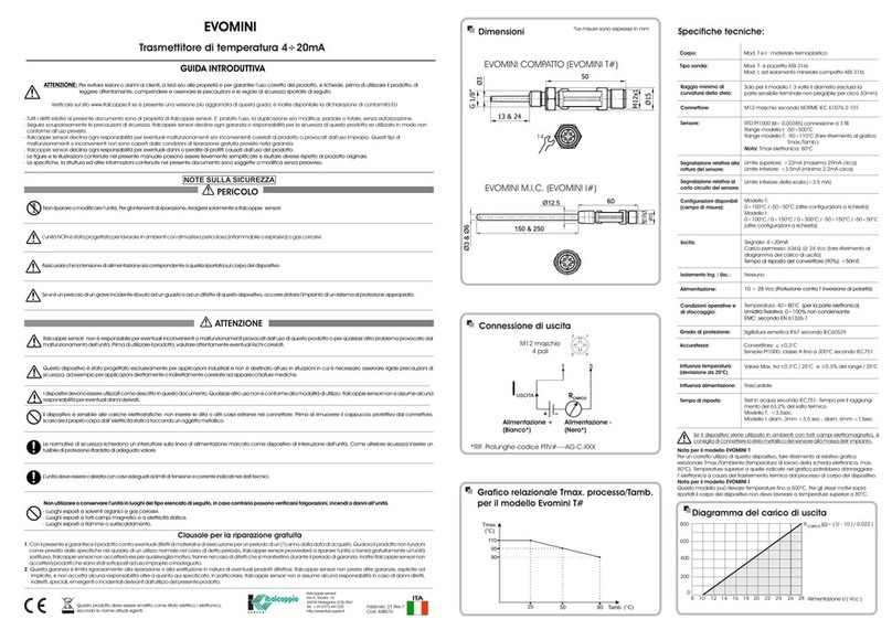
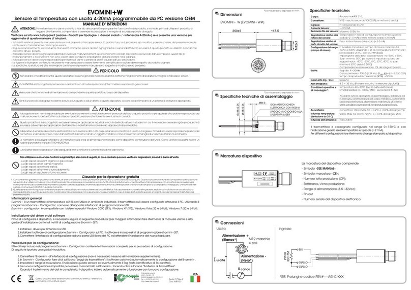
  9. ITALCOPPIE SENSORI EVOMINI SET User manual

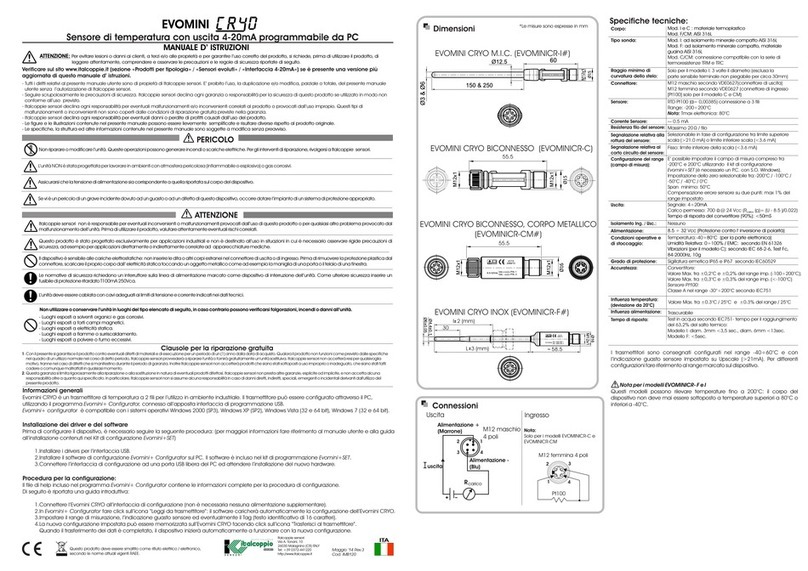
ITALCOPPIE SENSORI EVOMINI SET User manual

Input (to PC from USB interface)
Output (USB interface to
transmitter)
Power supply
Operative conditions
Galvatic isolation
USB Compliance
System requirements
O.S. Windows
Display resolution
Free hard disk space
Ports
PC' s USB port, 5Vdc 74mA max.
0…50°C / 0…90% RH
Non condensing
1500Vac
USB v1.1 and USB v2.0
Windows 7 (32 e 64 bit)
Windows 10
Minimum 800x600
50MB
This product should not be mixed with other kind of scrap after usage.
It should be handled as an electronic / electric device.
1 free USB port
The user instruction must be read prior to adjustment and/or installation.
All information subject to change without notice
February ’19 Rev.2
Cod. IMB089
UK
EVOMINI SET includes all necessary software and hardware for
configuration of all the Evomini+/CRYO/X product line from a PC's USB
port.
L' EVOMINI SET consists of:
!USB interface
!USB cable (connection between PC and USB interface)
!Adapter cable (connection between USB interface and
transmitter)
!Evomini Scat adaptor cable (connection between USB
interface and Evomini Scat transmitter)
!Software and drivers on a USB memory stick
Only one transmitter may be connected at a time.
The USB interface is CE-marked and complies with EMC-directive
2004/108/EC. For more information see the Declaration of Conformity.
The configuration software Evomini Configurator is compatible with
Windows 7 (32 and 64 bit), Windows 10.
Attention: when installing, do not connect the USB interface to your
USB port until prompted (please see the chapter “Installation
guide”).
Configuration kit for EVOMINI+/CRYO/X transmitter serie
USER’S MANUAL
Italcoppie sensori s.r.l.
Via A. Tonani, 10
26030 Malagnino (CR) ITALY
Tel: +39 0372-441220
http://www.italcoppie.it
TECHNICAL DATA
USB cable
Adapter cable with M12 female
connector or JST connector
EVOMINI SET
GENERAL INFORMATION
The USB interface is powered from the PC's USB port.
There are three LED indicators on the USB interface: “USB”, “PC” and
“DEV”. They are indicators to make the understanding of the
communication between PC and transmitter easier.
Their functions are described below.
!“USB” LED indicates data transfer. It lights during data transfer,
otherwise it is off.
!“PC” LED indicates connection between Evomini Configurator
and PC; it is green during reading or writing to transmitter
otherwise is red.
!“DEV” LED indicates the transmitter connection status. If it's green,
the connected transmitter is detected by the USB interface; when
it's red no transmitter is detected by the USB interface.
1. USB cable
2. Adapter cable for Evomini+/CRYO/X
3. Adapter cable for Evomini Scat
This product is warranted to be free from defects in materials and
workmanship for a period of one (1) year following the date of purchase.
Should the product fail to operate per specification in normal use during this
period Italcoppie sensori will repair the unit or provide a replacement free of
charge. Italcoppie sensori will not accept returns for any reason other than
defects during the warranty period, and will not accept any product that has
been misused, dropped, abused or inappropriately used or mistreated at any
time.
This warranty is strictly limited to repair or replacement-in-kind for defective
product. Italcoppie sensori makes no other warranty, either express or implied,
and will not accept liability beyond the remedies stated herein.
Specifically, Italcoppie sensori will not accept liability for direct, indirect,
special, consequential or incidental damages arising from the use of this
product.
Note: located in the memory stick there is an help file with the detailed
explanations how to install the drivers and the USB interface in the
different Windows O.S.
Following it is reported an summary introductive guide.
ATTENTION: before connect the USB interface to the PC it needed do
the following steps
Make sure your USB interface is not plugged in before driver
installation.
Inside this Kit it is included a memory stick with stored the
communications drivers and the Evomini+/CRYO/X serie configuration
software; connect the memory stick to a free USB PC's port and wait for
the automatic installation driver; when the message “hardware
installed and ready to use” appears, a windows is opened: click on
“Open folder to view files using Windows explorer”.
Double click on “SetupEvominiConfig.exe” to install the application
and the USB driver (you must be administator).
At the end of installation, connect the USB interface to a free PC' s USB
port, and wait for the installation: when the message “hardware
installed and ready to use” appears, it is possible start the Evomini
Configurator from the icon on desktop.
INSTALLATION GUIDE
Procedure for the transmitter configuration
Connect the device to USB interface by the adapter cable (see
“programming connection”) ; wait for the LED “DEV” becomes green
(it is no need an external power supply).
On Evomini Configurator click on “read from transmitter” icon : the
software will upload automatically the Evomini configuration.
Set the parameters of device
The new configuration can be downloaded on the device by a click
on “write to transmitter” icon. The device makes a restart after the
downloading is done.
For more detailed information, please see the Evomini Configurator
help; it is possible open the help by a F1 key from the application
main window.
PROVISIONS FOR FREE REPAIR
CONFIGURATION
1. “USB” LED
2. “PC” LED
3. “DEV” LED
USB INTERFACE DESCRIPTION CONTENTS
1.
2.
3.
4.
1.
2.
1. 2. 3.
Connection with
PC’s USB port
Programming
interface
Evomini+/CRYO/X
adapter
Evomini Scat
adapter
Evomini
Scat
Evomini+/CRYO/X
Don't power-on the transmitter
when connected with the
programming interface
USB
PC DEV
23
1
CONNECTIONS
This manual suits for next models

3

Other ITALCOPPIE SENSORI Transmitter manuals

ITALCOPPIE SENSORI EVOMINI User manual

ITALCOPPIE SENSORI

ITALCOPPIE SENSORI EVOMINI User manual

ITALCOPPIE SENSORI EVOMINI+W User manual

ITALCOPPIE SENSORI

ITALCOPPIE SENSORI EVOMINI+W User manual

ITALCOPPIE SENSORI EVOMINI CR40 User manual

ITALCOPPIE SENSORI

ITALCOPPIE SENSORI EVOMINI CR40 User manual

ITALCOPPIE SENSORI EVOMINI User manual

ITALCOPPIE SENSORI

ITALCOPPIE SENSORI EVOMINI User manual

ITALCOPPIE SENSORI EvominiSER User manual

ITALCOPPIE SENSORI

ITALCOPPIE SENSORI EvominiSER User manual

ITALCOPPIE SENSORI EvominiSER User manual

ITALCOPPIE SENSORI

ITALCOPPIE SENSORI EvominiSER User manual

Popular Transmitter manuals by other brands

Micatrone Micaflex PD ver 4 Installation & operation manual

Micatrone

Micatrone Micaflex PD ver 4 Installation & operation manual

Endress+Hauser Proline 500 PROFIBUS PA Brief operating instructions

Endress+Hauser

Endress+Hauser Proline 500 PROFIBUS PA Brief operating instructions

PC Electronics TX70-.1s user manual

PC Electronics

PC Electronics TX70-.1s user manual

Siemens SITRANS FUS060 PA quick start

Siemens

Siemens SITRANS FUS060 PA quick start

Camsat TCO 5807m quick start guide

Camsat

Camsat TCO 5807m quick start guide

BAPI Delta Style Installation and operating instructions

BAPI

BAPI Delta Style Installation and operating instructions

DPCAV AV681TX Assembly instructions

DPCAV

DPCAV AV681TX Assembly instructions

Canon Wireless File Transmitter WFT-E2 II A instruction manual

Canon

Canon Wireless File Transmitter WFT-E2 II A instruction manual

elero TempoTel 2 operating instructions

elero

elero TempoTel 2 operating instructions

M-system 10JPA instruction manual

M-system

M-system 10JPA instruction manual

DETRUM GAVIN 8C manual

DETRUM

DETRUM GAVIN 8C manual

WIKA S-11 operating instructions

WIKA

WIKA S-11 operating instructions

Teledyne OT-2 operating instructions

Teledyne

Teledyne OT-2 operating instructions

Zamel RNK-02 manual

Zamel

Zamel RNK-02 manual

RKI Instruments 65-2646XL0504SS Operator's manual

RKI Instruments

RKI Instruments 65-2646XL0504SS Operator's manual

Monacor IMG Stage Line TXS-820LT quick guide

Monacor

Monacor IMG Stage Line TXS-820LT quick guide

Wave Central Axis Series User and Programming Guide

Wave Central

Wave Central Axis Series User and Programming Guide

Marmitek Audio Anywhere 625 user manual

Marmitek

Marmitek Audio Anywhere 625 user manual

manuals.online logo
manuals.online logoBrands
  • About & Mission
  • Contact us
  • Privacy Policy
  • Terms and Conditions

Copyright 2025 Manuals.Online. All Rights Reserved.