Trillium Panther 306 Operating manual

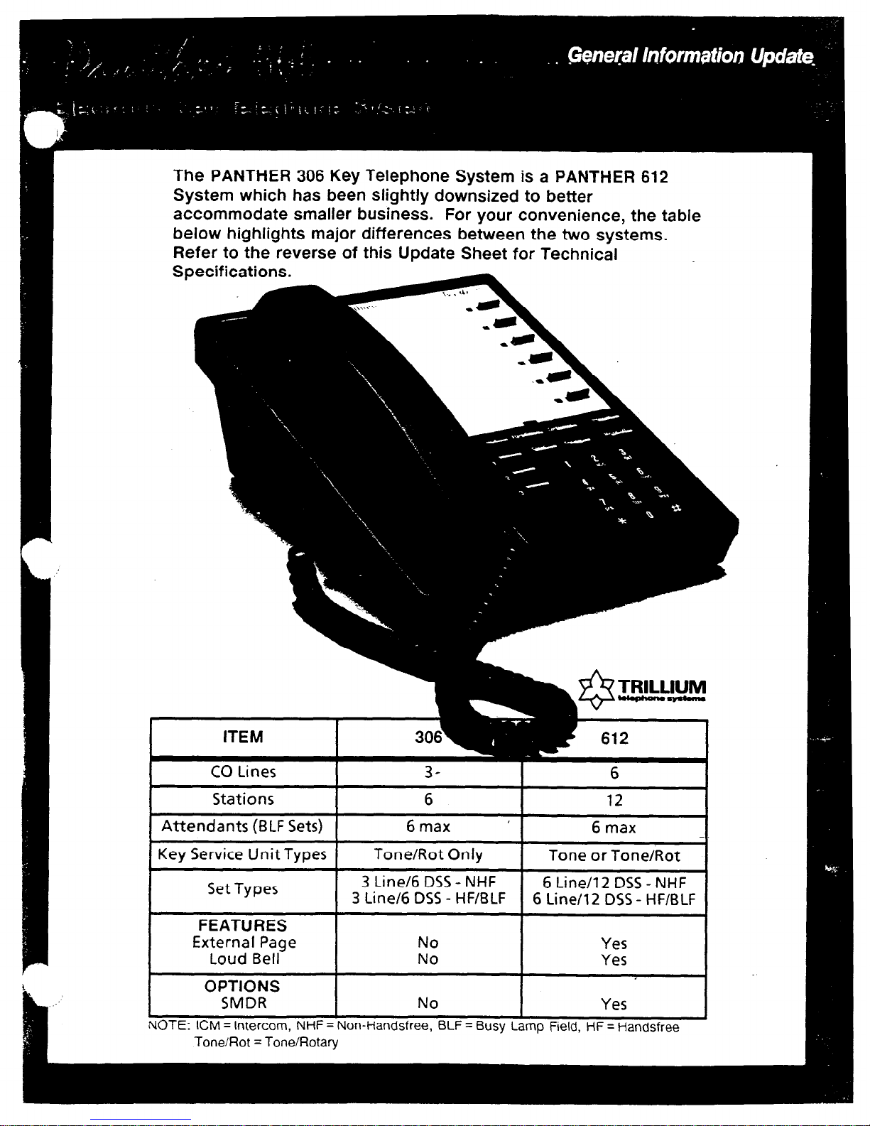
The PANTHER 306 Key Telephone System is a PANTHER 612
System which has been slightly downsized to better
accommodate smaller business. For your convenience, the table
below highlights major differences between the two systems.
Refer to the reverse of this Update Sheet
for Technical
Specifications.
ITEM
CO
Lines
Stations
Attendants (BLF Sets)
6
6max
’
12
6 max
I
I
Key Service Unit Types Tone/Rot Only
I
Tone or Tone/Rot
Set Types 3 Line/6 DSS- NHF 6 Line/l 2 DSS
-
NHF
3 Line/6 DSS- HF/BLF 6 Line/l 2 DSS- HF/BLF
FEATURES
External Page No Yes
Loud Bell No Yes
I
OPTIONS
SMDR No Yes
NOTE: ICM = intercom, NHF = Non-Handsfree, BLF = Busy Lamp Field, HF = Handsfree
Tone/Rot = Tone/Rotary

System Capabilities
Outside Lines
PANTHER Sets
Intercom Speech Paths
Attendant Sets
Door Modules
Power Fail Transfer
3 (2 with Door Answer)
5
6 max
2
1
Unit transfers 3 outside lines
to 3 standard phones
c
Power
AC Power Req.uirements
Station Loop Limit
110 Volts 2 10% (SO/60 Hz)
1 Amp max load
240 ohms max
(Equivalent to 2000 feet 24 AWG)
Environmental
Operating Temperature
Relative Humidity
Signaling
Number Plan
32°F to 104°F (0°Cto 40°C)
9Oohor less,non-condensing
Rotary Dial and/or Tone Dial
Station Numbers
Connectors
10 to 15
KSU Line Connectors
KSUSet Connector
KSU External Battery Connectors
KSU Door Answer Unit Connector
KSU Power Fail Transfer Connector
KSU Music Input
Set Connector
Lines 1 and 2, and 3 -4-conductor
modular
Sets 10 to 15 - 50-pin connector
Clips
6-conductor modular
4-conductor modular
Mono l/8 inch Mini Jack
6-conductor modular
- pins 2,3,4,5 interface to the Voice
and Data Pairs;
- pins 1and 6 provide an interface for
connecting an external amplifier to
the speaker terminals
Specificabcms and features are sub;ect to change without notice.
U.S. Marketing HeadquarterstU.S.O$berations International Sales
Trillium TekpMne Systems Corporation Trillium Telephone Systems kc
1675 MacArthur Blvd., 603 March Road, P.O. BOX 1330, Kanaz, Ontara K2K 1X3
Costa Mesa, C&forma 92626, Tel.: (714) 557-3300 Telex: 0534524. Tel.: (613) 592-2550. Fax: (613) 592-2555
Canadian Sales
Trillium Tetephone Sales Inc.
155 Gordon Baker Road, Suite 206, WIllowdale,
I
@ Copyrght 1987 TRILLIUM Telephone Systems MC.
TMTrademark of TRILLIUM T&phone Systems II-C.

Station Select/Speed Call - dual-
function keys used to make intercom paging
announcements and to dial private speed call
numbers.
Redial - used to redial the last number
manually dialed from your Set.
Line
- used
to select any of the outside
lines (unless programmed otherwise).
Hold - places outside calls on hold and
exclusive hold.
Conference - for setting up three-party
add-on conference calls.
Flash/Cancel - programmable as a
calibrated hookswitch flash or cancel, but not
both:
Flash
provides a calibrated on-hook signal
which is required to access most PBX,
Centrex and network features.
Cancel is used to cancel external calls and
return dial tone without hanging up the
handset.
Speed - used to enter pnvate and common
speed call numbers into the system’s memory;
also for dialing speed call numbers.
Speaker
-
turns the Set’s speaker on and
off; also used to end a handsfree call.
9
10
11
12
13
14
15
16
Mic On/Off - turns the Set’s microphone
on and off for handsfree calls.
Intercom
-
used to perform internal call
transfers, activate paging, background music
and various other features.
Ringer Volume Control - controls the
volume of the tone ringing.
Speaker Volume Control
-
controls the
volume of the speaker audio.
Station Indicator Lamps
-
(Panther 306
Attendant Set only) - turn on when the
corresponding Set is busy on a call.
Asterisk (Jt)
-
when the * is dialed as ‘4%
first digit in a telephone number sequence the
last outside line used at your Set is
automatically selected. (The handset must be
in the cradle).
Pound (#)
-
when the # is dialed, the
internal intercom line will be automaticalty
selected, provided the handset is in the cradle
and all speech paths are not in use.
Handset
-
used to place call5 in the
conventional handset manner. Provides more
privacy man the handsfree method.

To use most of the PANTHER 306 system features, follow
the PANTHER 612 operating instructions given in the
PANTHER User Guide and the PANTHER Quick Reference
Guide. PANTHER 306 system features which operate
differently are described below.
Private Speed Call - Dialing
To
speed call one of your first 5 Private numbers -
l
Lift the handset.
Press the Line key of an outside line.
Handsfree -
Turn the MIC. on/off indicator on.
Handsfree -
Press the Line key of an outside line or press *
Dial tone is heard; line indicator winks.
l
Press desired Speed Call key_(DSS
keys 11-15).
The number is automatically speed dialed.
OR
To speed call one of your last 6 Private Speed numbers
l
Lift the handset. Press the Line key of an outside line.
Handsfree -
Turn the Mic. on/off indicator on.
Handsfree -
Press the Line key of an outside line or press Jt.
Dial tone is heard; line indicator winks.
l
Press the Speed key.
l
Dial the desired Speed Call Code
(from 05 to 10).
The number is automatically speed dialed.
Private Speed Call - Storing
To store your first 5 Private Speed Call entries -
l
Press
the Speed key.
l
Dial the entry to be stored including any pauses, halts, flashes.
Continuous tone is heard; intercom indicator winks.
l
Press the desired Speed Call key (11-15).
Maximum 26 digits.
Intercom indicator flashes.
Contmuous tone stops; indicator continues to flash.
l
Write the entry on
the designation card.
l
Repeat above procedure for each entry to be stored.
To store your last 6 Private Speed Call entries
-
l
Press the Speed key.
Continuous tone is heard; intercom indicator winks.
l
Dial the desired speed call code (05 to 10).
Intercom indicator flashes.
l
Dial the entry to be stored including any pauses, halts, flashes.
Maximum 26 digits.
Continuous tone stops; indicator continues to flash.
l
Write the entry on the designation card.
l
Repeat above procedure for each entry to be stored.
Door Answering
Line key 3 is used to access the Door Module.
To answer a door
call
(from either Module)
-
Distinctive tone ringing is heard. Line 3 indicator flashes.
l
Lift the handset; press Line key 3.
Handsfree -
Turn the Mic. onloff indicator on; press Line key 3.
tine 3 indicator winks.
The visitor
at the door need only speak in the direction of
the Door Module.
To place an intercom call to Door Module One -
l
Lift the handset; press Line key 3.
Handsfree -
Turn the Mic. on off indicator on; press Line key 3.
One ringing burst is heard; line 3 indicator wrnks.
. F 1
l
Make your announcement.
The called
party
answers by speaking in the direction of
the Door Module.
To
end
a Door
Module conversation -
l
Hang up the handset.
Handsfree -
Press the Speaker key.
Line 3 indicator turns off.
Features that do not apply to the PANTHER 306 System:
Music through external paging
SyStetII
Cell the attendant by dialing 0
Non-appearing line access Message waiting from the attendant
Call Data Recording operations Loudspeaker Paging
Specrficaf/ons and features are subject lo change without notice.
U.S. Marketing Headquarters/U.S.Operations
Trlllwm T&phone Systems Corporation
1675
MacArthur Blvd.,
Costa Mead. California 92626, Tel.: (714) 557-3300
Canadian Sales
TrGum Telephone Sales Inc.
I 55 Gordon
Baker Road. Suite 206. Wlllowdale.
Ontano, M2H 3N5 Tel.:
(416)
494-0522
International Sales
Tnllwm Telephone Systems Inc.
603 March Road, P.O. Box 13030, Kanata, Onlano. K2K 1X3
Telex 053-4524, Tel.: (613) 592-2550, Fax: (613) 592-2555
@Copynght 1987 TRILLIUM Telephohe Systems Ix.
TMTrademark of TRILLIUM Telephone Systems Inc
91-0363-2A
-
March 1987
-
Pnnted in Japan
F-301 4-l
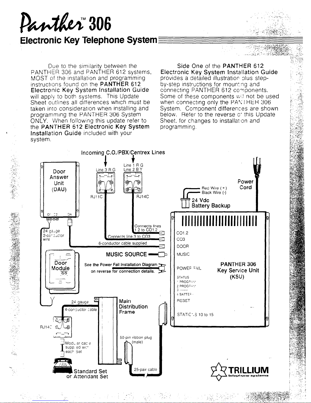
bNcY. When following this update-refer to
Due to the similarity between the
PANTHER 306 and PANTHER 612 systems,
the PANTHER 612 Electronic Key System
MOST of the installation and programming
instructrons found on the PANTHER 612
Installation Guide
included with your
Electronic Key System installation Guide
will apply to both systems. This Update
system.
Sheet outlines all differences which must be
taken into considerarron when installing and
proaramminq the PANTHER 306 System
Side One of the PANTHER 612
Sheet. for changes to installar’on and
Electronic Key System installation Guide
provides a detailed illustration olus step-
programming.
by-step instructions for mount,ng and
connecting PANTHER 612 components.
Some of these components V/I not be used
when connecting only the PANTHER 306
System. Component differences are shown
below. Refer to the reverse o’ this Update
Incoming,C.O.iPBX/~entrex Lines
Door
Answer
Unit
PAW
f v
Line 1 R G
Line 3 R G Line 2 B Y
&conductor cable supplied
MUSIC SOURCE e
See the Power Fail Installation Diagram
on reverse for connection details.
Standard Set
or Attendant Set
Main
Distribution
Frame
DOOR
MUSIC
PANTHER 306
POWEF =IIL
Key Service Unit
STATUS WW
. ;)R(-JG= 1’.’
1 DROG=“.’
j .
13*n::.
I
RESET
STATIC’.5 10 to 15
50-pin ribbon plug
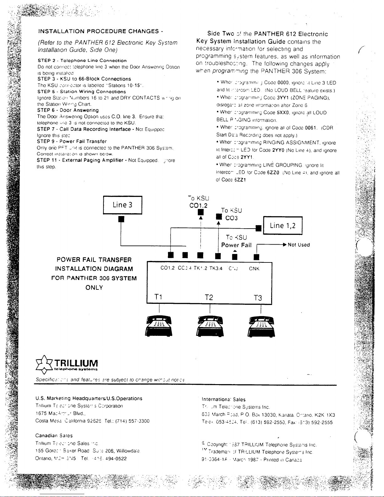
INSTALLATION PROCEDURE CHANGES -
(Refer to the PANTHER 612 Electron/c Key System
lnsta//arron G&e, S/de One)
STEP 2 - Telephone Line Connection
Do not COI!~HX! :clephone Irr~e 3 when Ihe Door AnswcrrnG Oo\ron
IS bcrny rrxi&x
STEP 3 - KSU to 66-Block Connections
The KSU ;wr :.z.1or IS labelled “SLattons 10-15”.
STEP 5 - Statron Wiring Connections
Ignore SIZ:,G~! Vi,irnbers 16 IO 21 and DRY CONTACTS LA:“1’~ or,
the StaIror Wjr,c~g CharI
STEP 6 - Door Answering
The Door ir!swerrrlg Option uszs C.O. lrne 3. Ewurc [ha:
lelephoric ..:ii’ 3 s no! connecreo to Ihe KSU.
STEP 7 - Call Data Recording Interface - Not Equlppes
Ignore 1t11s s!e:
STEP 9 - Power Fail Transfer
Only on’c P’T .:;II IS connecwc !o the PANTHER 306 SYS:~T.
Correct rns:a!‘a! 3n IS shown w:ow.
STEP 11 - External Pagrng Amplifier - NOI Eourpped ..?ore
lhrs sleo.
Side Two ;! the PANTHER 612 Electronic
Key System Installation Guide contains the
necessary infer-nation for selecting and
programmlng s,stem features. as well as tnformation
on :roubleshoz:,ng. The followrng changes apply
wFen progran-ung the PANTHER 306 System:
l
Whet :‘j,,ra~nm\. ; Coce 0000, qncri 81Line 3 LED
and III .f’~or’: LE3 INo LOUD BELL ‘?diure CXISIS )
l Whe.
:-;yra:‘lnw_: Coci: 3YYl (ZONE PAGING).
alsregz: 3;I zone 10’3rn-~a:lon a!ler Zorw 6
l
Wher ;~x4rawrnrr:j Coae 5Xx0. lgruri: all LOUD
BELL P ‘.GING rr::owat1on.
l
Whe!’ r’~yramnwy. Ignore all of Cooe 0061. (CDR
Srarl Dz.2 Reczrdq does not apply.)
l
Wher I-sgra’wirrq RINGING ASSIGNMENT. qnore
111Inter:: -. LE3 ior CoUe 2YY0 (No Ltw 1). arid lynore
all of c:a:< 2YYl
l
Wher- r-~yrammrng LINE GROUPING qoore 111
interco-. -ED ror C;de 6220 iNo Lrne 11, and Ignore all
of Coaf 6221
-0 KSU
.I Line 1,2 I
POWER FAIL TRANSFER
INSTALLATION DIAGRAM
FOR PANTHER 306 SYSTEM
ONLY
C01.2 CC: 2 TK’ 2 TK3.4 C’.: CNK
TRILLIUM
teltphsmsystefns
-.
Spef2rfrc.c :.‘i and fea:,‘es zre subject 10 crsnge WI:-:.A nor :f
U.S. Marketing HeadquartersU.S.0peration.s Internationa’ Sales
Trlllrurn T+ ?I’ xe Sys[e,- s ‘Czrporatrorl Tr ..m Tele: :rle S;srerl:s Inc.
1675 Ma::,:*.-’ Blvd., 62: h,farch =:.;j, P 0 Bsl 13030, li3nala r?:wo. K2K 1X3
Costa M51.2 C-;lrforn~a 92625 Tel.: (714) 55i-3300 Tee; 0%::::. Te; (613) 592-2555. F& .5’3) 592-2555
Canadian Sales
Trrllrunl T< $;’ xe Sales “,c
155 Gore: . s.t=:er Roac 3~ ._ 206, Wrllowda:e
Ontarro. *,‘.I- :‘J5 Tel ‘1: 494-0522
.
‘C ,-
tizoyrryh: -37 TalLLI’JM Telephone .Sys:?:,js Inc
Tk’ Tradema.. :I TR’LLIUM Telephor:? Sys!e’--j lnc
3: -:364-l; ‘.larc’, 196: Prlnred I:, Cana-:

Technical Service Manual
\.
. . . . . . . . . . . . . . . . . . . . . . . . . . . . . . . . . . . . . . . . . . . . . . . . . . . . . . . . . . . . . . . . . . . . . . . . . . . . . . . . . . . . . . . . . . . . . . . . . . . . . . . . . . . . . . . . . . . . . . . . . . . . . . . . . . . . . . . . . . . . . . . . . . . . . .,... . . . . . .._ . . . . . _. . . .., . . .
:::::::::::;::::“‘.......‘........................:~:::::~:~:;::::::::::::::::::::::::::: . . . . . . . . . . . . . . . . . . . . . . . . . . . . . . . . . . . . . . . . . . . . . . . . . . . . . * . . . . . ** . . . . . . . *a . . . . . . . . . . . . . . . . . . . . . . . . . . . . . . . . . . . . . . . . . . . . ..--.............................................................
. . . . . . . . . . . . . . . . . . . . . . . . . . . . . . . . . . *
-Panther 306/Panther 612
Electronic Key Telephone Systems
NOTE
i.
Whentheorganizationfor thismanualwasfirst conceived,mostchapterswere
designedtoincludemorethanonesystem- sincealargenumberof functions,
features,andcharacteristicsarecommontoTFULLIUM’stelephonesystems.
Forexample,thePanther306and612ElectronicKeyTelephoneSystemsare
very similar;coverageof thesetwo systemswastohavebeencombinedinto a
singlechapter- asevidencedbythesinglePanther306/612tab.
However,interruptingthe
flow
of textandgraphicstoidentifyandexplainthe
differencesbetweenthesesystemsprovedtobetoodisruptive- andthepoten-
tialfor readerconfusionbegantooutweighthebenefitsof sharedcoverage.
In the
end,givingeachseparatesystemitsownchapterwasjudgedtobemuch
moreusefulto fieldinstallersandtechnicians(thismanual’sprimaryaudience)
in theirnormalworkenvironment,undertheirnormaloperatingcircumstances.
Therefore,thePanther306system- andonly thePanther306system- is
thesubjectof thefirst chapterunderthistab(startingatthefirst redpage),fok
lowedbytheseparatePanther612chapter(startingatthesecondredpage).
:::::::::::::::::::::=::::::::::::::::::::::::::::::::::::~:::::::::::::::::::::::::::::::::::::::::::::::::::::::::::::::::::::::::::::::::::::::::::::::::::::::::::::::::::::::::::::::::::::::::~~:::~::~::::::::::=::::::::::::::~:::::::~:::::::::::,
I
L.
TRILLIUM Telephone Systems

..................... .~..
f
Technical
Service
Manual
Table of
Contents
. . . . . . . . . . . . . . . . . . . . . . . . . . . . . . . . . . . . . . . . . . . . . . . . . . . . . . . . . . . . . . . . . . . . . . . . . . . . . . . . . . ” . . . . . . . . . . . . . . . . . . . . . . . . . . . . . . . . . . . . . . . ........... -- ....... - .............................................................................................................................,
. . . . . . . . . . . . . . . . . . . . . . . . . . . . . . . . . . . . . . . . . . . . . . . . . . . . . . . . . . . . . .e.. . . . . . . . . . . . . . . . . - . . . . . . . . . . . . . . . . . . . . . . . . . . . . . . . “.. . . . . . . . . . . . . -..* . . . . . . ......................................... ... .......................... * ........... . ........................................
Topic Page
Chapter Introduction
PREFACE ....................................................................................................................................................
Intro-l
ABOUTTHIS CHAPTER.. .............................................................................................................................. Intro-l
QUICK-REFERENCE CHART .......................................................................................................................... Intro-2
SectionA - FCC Requirements
RADIO AND TELEVISION INTEW;ERENCE ...................................................................................................... A-l
HEARING AID COMPATIBILITY ....................................................................................................................... A-l
RESPONSIBILITIES ......................................................................................................................................... A-2
User Responsibiliti es..................................................................................................................................... A-2
Telco Responsibilities ..................................................................................................................................... A-2
SectionB - SystemComponents
STANDARDCoh4.Po~ ..............................................................................................................................
B-l
One Key Service Unit (KSU) ........................................................................................................................... B-l
Up
to Six Telephone Sets.. ............................................................................................................................. B-l
OPTIONAL COMPONENTS ................................................................................................................................ B-2
One Door Answer Unit .................................................................................................................................. B-2
One Power Fail Transfer Unit ......................................................................................................................... B-2
Up to Five Off Premises Extension/Data Interface (OPX) units.............................................................................. B-2
Set Stands/Wall-Mounts.. ............................................................................................................................... B-2
Designation Cards. ........................................................................................................................................ B-3
Face Plates................................................................................................................................................... B-3
SectionC - Technical Specifications
CONNECTORS ................................................................................................................................................. C-l
ENvIRONMENTALREQUIREMENTS ................................................................................................................ C-l
POWERREQUIREMENTS .................................................................................................................................. C-l
STATION NUMBERING PL.AN........................................................................................................................... C-l
SYSTEM CAPABILITIES ................................................................................................................................... C-l
:::::::::::::::::: ..“.::z :::::::: ::::::::::::::: 1 ::::: “. ::::::: ~~::::y~:::::::: ::::............... - . . . . . . . . . . . . . I-.. . . . . . . . . . . . . . . . .
. . . . . . . . . . . . I.......... . . . . . . . . . . . - . . . . . . . . . . . . . . . . . . .
i.
. . . . . . . . . . . . - . . . . . . . . .
. . . . . - . . . . . . . . . - . . . . . . . . . . . . . . . . . . . . . . . . . . . . . . ..-.-..........................................
. . . . . ..- ,,..............” . . . . . . . . . . . . - . . . . . . . . . . . . . . . . . . . . . . . . . . . . . . . . . . . “......I
TRILLIUM
Telephone
’Panther.306
Systems
Page i
................................. ......... .
Table of
’Technical
Service
Contents
Manual .
.............._................................................................
:::::::::::::::::::::::::::::........................,............ ............................................................................-......-............-...................- ........................................
..................................a.......
.....................................................”................................”............................- .......................................
c ”
Topic Page
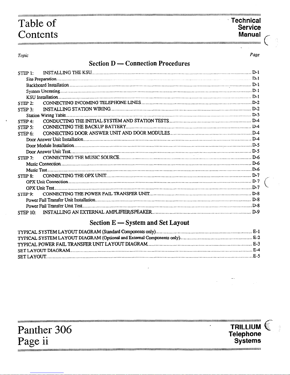
SectionD - Connection Procedures
STEP 1: INSTALLING THE KSU................................................................................................................... D-l
Site Preparation. ........................................................................................................................................... D-l
Backboard Installation .................................................................................................................. :............... D-l
System Uncrating ......................................................................................................................................... D-l
KSlJ
Instalhtion
........................................................................................................................................... D-l
STEP2 CONNECTING INCOMING TELEPHONE LINES ................................................................................ D-2
sTEP3: INSTALLING STATION WIRING ..................................................................................................... D-2
Station Wiring Table..................................................................................................................................... D-3
< STEP 4: CONDUCTING THE INITIAL SYSTEM AND STATION TESTS.. ......................................................... D-4
STEP 5: CONNECI’ING THE BACKUP BA’ITERY .......................................................................................... D-4
STEP 6: CONNECTING DOOR ANSWER UNIT AND DOOR MODULES.. ......................................................... D-4
Door Answer Unit Installation ........................................................................................................................ D4
Door Module Installation ............................................................................................................................... D-5
Door
Answer
Unit Test., ................................................................................................................................. D-5
STEP 7: CONNECI’ING THE MUSIC SOURCE ................................................................................................ D-6
Music Connection ........................................................................................................................................ D-6
Music
Test .................................................................................................................................................. D-6
STEP 8: CONNFLTING THE OPX UNIT ........................................................................................................ D-7 /
OPX Unit Connection ...................................................................................................................................
OPX Unit Test .............................................................................................................................................
STEP 9: CONNECTINGTHEPOWERFAILTRANSFERUNIT. ........................................................................ D-8
Power Fail Transfer Unit Installation ............................................................................................................... D-8
Power Fail Transfer Unit Test ......................................................................................................................... D-8
STEP lo: INSTALLING AN EXTERNAL AMPLIFIER/SPEAKER ...................................................................... D-9
SectionE - Systemand SetLayout
TYPICAL SYSTEM LAYOUT DIAGRAM (Standard Components only). .................................................................... E-l
TYPICAL SYSTEM LAYOUT DIAGRAM (Optional and External Components only). .................................................. E-2
TYPICAL POWER FAIL, TRANSFER UNIT LAYOUT DIAGRAM.. ........................................................................ E-3
SET LAYOUT DIAGRAM .................................................................................................................................. E-4
SETLAYOUT.. .................................................................................................................................................. E-5
” :::::. ‘:‘=-,‘*~:~.:~:~::::::::::::“‘......... * ..*.... . ..~..............::: :7”‘“‘:.;: ye: y::““‘::“““” :::. 2:: ::::::::::: :::::::::::::::::::::. z :::::::::::::::::::: :” ::::::::: :“:::z :::::::::::: “< :::::::::: ::“:
. . . . . . . . . . . . . . . . . . . . . . . . . . . . . . . . . . . r
Panther
306
Page ii I
TRILLIUM &
Telephone
Systems
Technical
Service
Manual
’Table of
Contents
SectionF - Feature Programming
FEATURE CATEGORIES .................................................................................................................................... F-l
Categories Versus Codes............................................................................................................................... ..F- I
Referencing Categories to Codes................................................................................................ ...................... F-l
Interrelated Features..................................................................................................................................... ..F- 1
Feature Programming Cross-Reference Table ..................................................................................................... .F-2
SYSTEM-WIDE FEATURES .............................................................................................................................. ..F-4
System-Wide Feature Programming Table .......................................................................................................... F-5
INDIVIDUAL SET FEATURES ............................................................................................................................ F-8
Individual Set Feature Programming Table. ........................................................................................................ F-9
INDIVIDUAL LINE FEATURES .......................................................................................................................... F-10
Individual Line Feature Programming Table ..................................................................................................... F-11
INDIVIDUAL GROUP FEATURES ..................................................................................................................... F-12
Individual Group Feature Programming Table .................................................................................................... F-13
SPEED CALL NUMBERS .................................................................................................................................. F-14
Speed Call Programming Notes...................................................................................................................... F-14
Common Speed Call Numbers ........................................................................................................................ F-14
Private Speed Call Numbers. .......................................................................................................................... F-15
FEATURE DESCRIPTIONS ............................................................................................................................... F-15
SectionG - Operating Instructions
OPERATING INSTRUCTIONS TABLE ..................a..... ........................................................................................G-l
SectionH - Troubleshooting
TROUBLESHOOTING TABLE.. ................................................................................................_..._.................... H-l
I
c
I
TRILLIUM
Telephone
Systems
Panther 306
Page iii
Technical
Service
Manual
PREFACE
The Panther 306 Electronic Key Telephone System is a
state-of-the-art system that incorporates sophisticated elec-
tronics to meet the communications needs of today’shome,
offke, and small business user.
It connectS three outside tone or rotary telephone lines (only
two if the optional Door Answer Unit and Door Modules are
installed) with up to six station Sets- which are all wired
in a star configuration. Both Handsfree and Non-Handsfree
< Sets are available; the Handsfree Sets also include Busy
Lamp Field (BLF) indicators that show the status of all sys-
tem stations.
Common and private speed call numbers, call transferring,
door answering (with optional Door Answer Unit and Door
Modules), internal monitoring, conferencing (up to 3 par-
ties), internal intercom paging (station-to-station, zone, and
all page paging), and last number redialing are just some of
the many features offered.
The attractive. well-designed system makes feature pro-
gramming and operation very easy. In addition, the Panther
system is designed to allow easy interfacing with modems
and answering devices through an optional OPX device.
The fully sealed Panther 306 Electronic Key Telephone
System may be installed in either a standalone mode or be-
hind a CENTRJSX or PBX. The microprocessor-controlled
circuitry operates all system communications and the flexi-
ble programming.
An optional external backup 24 V battery can be connected
to the system; the backup battery is automatically brought on
line in the event of a power failure, thus preventing interrup-
tions in telephone service.
Also, in the event of a total system failure, incoming lines
will be transferred to standard sets if the optional Power
Transfer Unit has been installed in the system.
ABOUT THIS CHAPTER
This chapter has also been designed specifically to enable
technicians to install, operate, and maintain the Panther 306
Electronic Key Telephone System. Information is presented
in a logical order, without undue wordiness - to help the
technician find, understand, and use the relevant informa-
tion, quickly and easily.
Therefore, for example, the Connection Procedures are sep-
arated into concise steps that have a logical and necessary
sequence; and reference material (Technical Specifications,
Feature Programming, Operating Instructions, and
Troubleshooting) is presented in a variety of easy-to-follow,
visible-at-a-glance tabular formats.
To acquaint yourself with this chapter, please review the
Table of Contents and spend a few moments browsing
through the different sections.
CAUTION
Panther equipment is sealed. Breaking the seal
will void your warranty.
If you have an installation, operation, or troubleshooting
problem that you cannot solve by using this chapter (and that
your dealer cannot help solve), call TRILLIUM Customer
Service at l-800-848-2444 (inside California, call 1-800-
422-7600).
NOTE
For your ready reference, a chart summarizing
indicator signals appears on the back of this
page-
TRlLLlUM
Telephone
Systems
Panther 306
Page Intro-l
1
Chapter
Introduction
Technical
Service
Manual
:::::::::::::::::::::::::::::::::::::::::::.................................................................,..I.-...a.....,....-,.....,.............- .....................................
...................................................................................u ....s.............- ......_.....”......................................................_ ...........,,....,...,................
.................................,.I ...............n....................... c.
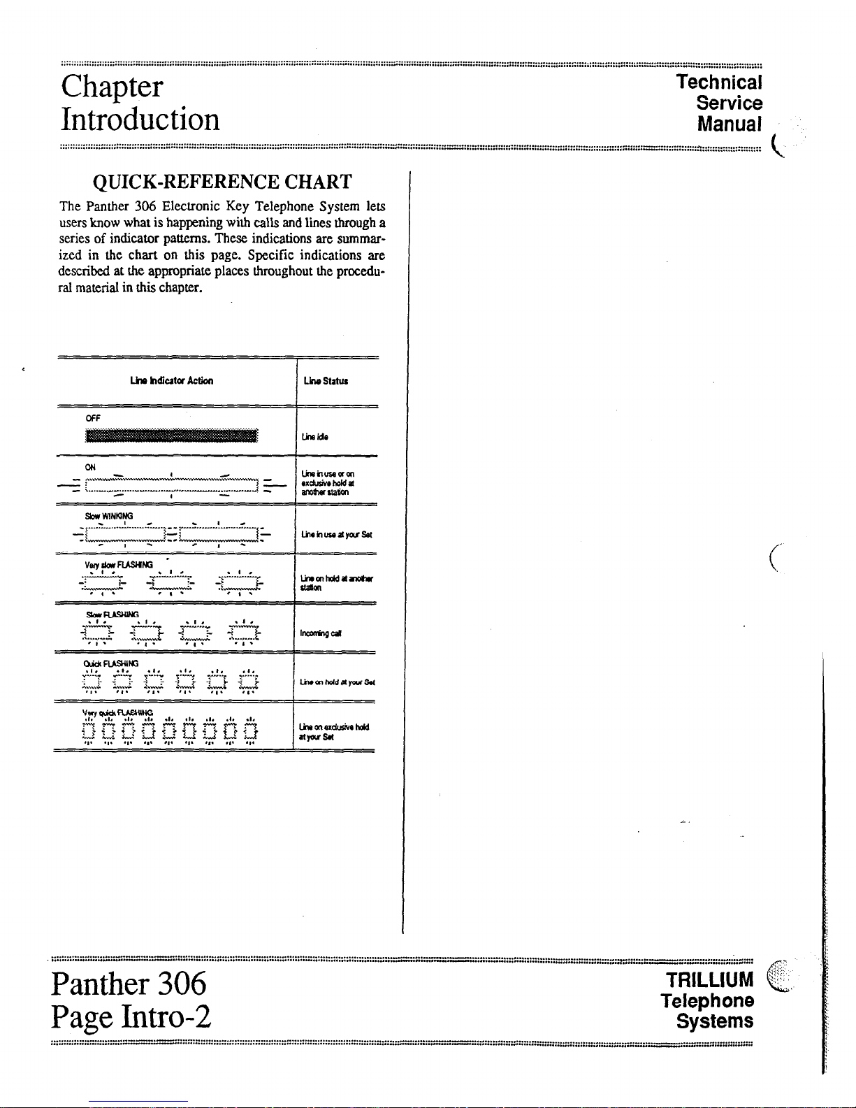
QUICK-REFERENCE CHART
The Panther 306 Electronic Key Telephone System lets
usersknow what is happening witi calls and lines through a
series of indicator patterns. These indications are summar-
ized in the chart on this page. Specific indications are
described at the appropriate places throughout the procedu-
ral material in this chapter.
cu Linutiuseaan
- ....- ..,~......-.......!...,
-: IL
- ..,,._._.-......-" ..-. ~....-...-...--,.,,...-...-,..,,.1 rxdu3iwhoida
-
I anoswua~
S&WWINkING I
_ -
-( .....*.. ....A .....f... ...i,‘“““’ .....! _.......i, ..,. _
-t k-:..-“---.4--A Lhrhuseayous4
- I - 0 I -
vwyskwFusHffi -
.r;;-;c -p-!&
-:
&-,&A-
.;.A.“‘“.+
&.-..A7
.
TLyy..g
I
umfflhddanotu
aam
- I . - I *
TRILLIUM &,
Telephone
Systems

....._................................................................._.......................................................- ............................
...............
...............................................................................................................-............................::::::::::::::::::::::::::::::::::::::::::::::::::::::::::::::::~::::::::::::::::::::::::::::::::~
Technical
Service
FCC
Manual
Requirements
.............................................................
...................................................
..........
..“‘........::::::::::::::::::::::::::::::::::::::::::::::::::::~~:::::::::::::::::::::~::::::::::::::::::::::::::::::::::::::::~:::::::::::::::;~::::::::::::::::::::::::::::::::::::::::::::::::::::
RADIO AND TELEVISION
INTERFERENCE
WARNING
The Panther 306 Electronic Key Telephone
System generates and usesradio-frequency en-
ergyand- if not installed and used in strict
accordance with these instructions - may
cause interference to radio and television
reception.
The Panther 306 Electronic Key Telephone System hasbeen
certified to comply with the limits for a Class B computing
device, pursuant to Subpart J of Part 15 of the Federal
Communications Commission (FCC) Rules which are de-
signed to provide reasonable protection from radio and
television interference in a residential installation. However
there is no guarantee that interference will not occur in a
particular installation.
If interference is encountered, test to determine if the unit is
at fault by unplugging the Key Service Unit (KSU) from the
wall outlet..
If unplugging the KSU removes the interference, try the fol-
lowing corrective measures, singly or in combination, until
the interference is eliminated:
l
Change the location or position of the indoor re-
ceiving antenna of the radio or television.
.
Relocate the Panther 306 Set or KSU in relation to
the radio and television receivers experiencing
interference.
.
Plug the KSU into an outlet that does not also serve
radio or television sets.
If further help is needed, consult your TRILLIUM dealer or
an experienced radio/television technician - or refer to the
FCC’s booklet, “How to Identify and Resolve Radio-TV
Interference Problems.” It is available from the US
Government Printing Office, Washington, DC 20402 (stock
number CQ4-000403454).
HEARING AID COMPATIBILITY
The Panther 306 Set is compatible for those requiring a
hearing aid as defined in section 68.316, Part 68 of FCC
Rules.
L
TRILLIUM
Telephone
Panther 306
Systems
Page A-l
FCC
Requirements
‘Technical
Service
Manual
...............................................................................................................a..........
..............................................................................-...........-.......................................................
......................................*
,...*...........*a....................................................*..........a.........................................................a.....................”............- ..................
.,...........,.....,.............,.,
e
RESPONSIBILITIES
The FCC’s rules permit the Panther 306 Electronic Key
Telephone System to be connected to the telephone network
via a jack or jacks provided by the telephone company
(telco). Thesejacks are not provided for coin or party lines.
- UserResponsibilities
Before connecting your Panther 306 Electronic Key
Telephone System to the telephone lines, you must contact
the telephone company and provide them with the following
c information:
. Telephone numbers of the lines to which the
Panther 306 Electronic Key Telephone System is to
be connected (lines 1,2, and 3)
. FCC Registration Number (found on the side of the
Key Service Unit or KSU: tire number for the
Panther 306 Electronic Key Telephone System is
EBS7ST-71737-KF-E)
. Ringer Equivalence Number (also found on the side
of the KSU: the number for the Panther 306
Electronic Key Telephone System is33B)*
l
USOC jacks required (usually one Q-conductor,
RJ14 modular jack for lines 1 and 2; and one 2-
conductor RI 11jack for line 3)
You also have the responsibility to disconnect a malfunc-
tioning Panther 306 Electronic Key Telephone System from
the telephone lines until the cause of the malfunctioning is
identified and repaired. Otherwise, the telephone company
may temporarily disconnect service.
* The Canadian Department of Communications load num-
ber for the Panther 306 Electronic Key Telephone System is
16B.
Telco Responsibilities
The telephone company isrequired to give you adequate no-
tice of any changes it makes in its technical operations or
procedures that may affect the compatibility or use of your
Panther 306 Electronic Key Telephone System.
, . . . . . . . . . . . . . . . . . . . .
,..............,...... - “::::::::::::::::::::::::::::~~:::::::~~:~~:::::::::::::::::::::::::::::::~:;:::::::::::::;:~:::::::::::::::::~:::::::::::::::::::::::::::::=::::~~=:;::::::~:::::::::::;:::::::”:::
I
Panther 306 TRlLLiiJMc 1,
...<.
Page A-2
Telephone
Systems
..............................................................................................
.........................- ..................................................................................................................-....
................................................................................................*.......................- ....................................................................................................-”........,......:::::::::::::::::::::::::::
Technical
Service
System
Manual
Components
........................................................................................................................- .........................................
,..................................................................*...a...............................................- .......................................
::::::::::::::::::::::::::::::::::::::::::::::::::::~::::~::::::::~::::::::::::::::::::::::::::;
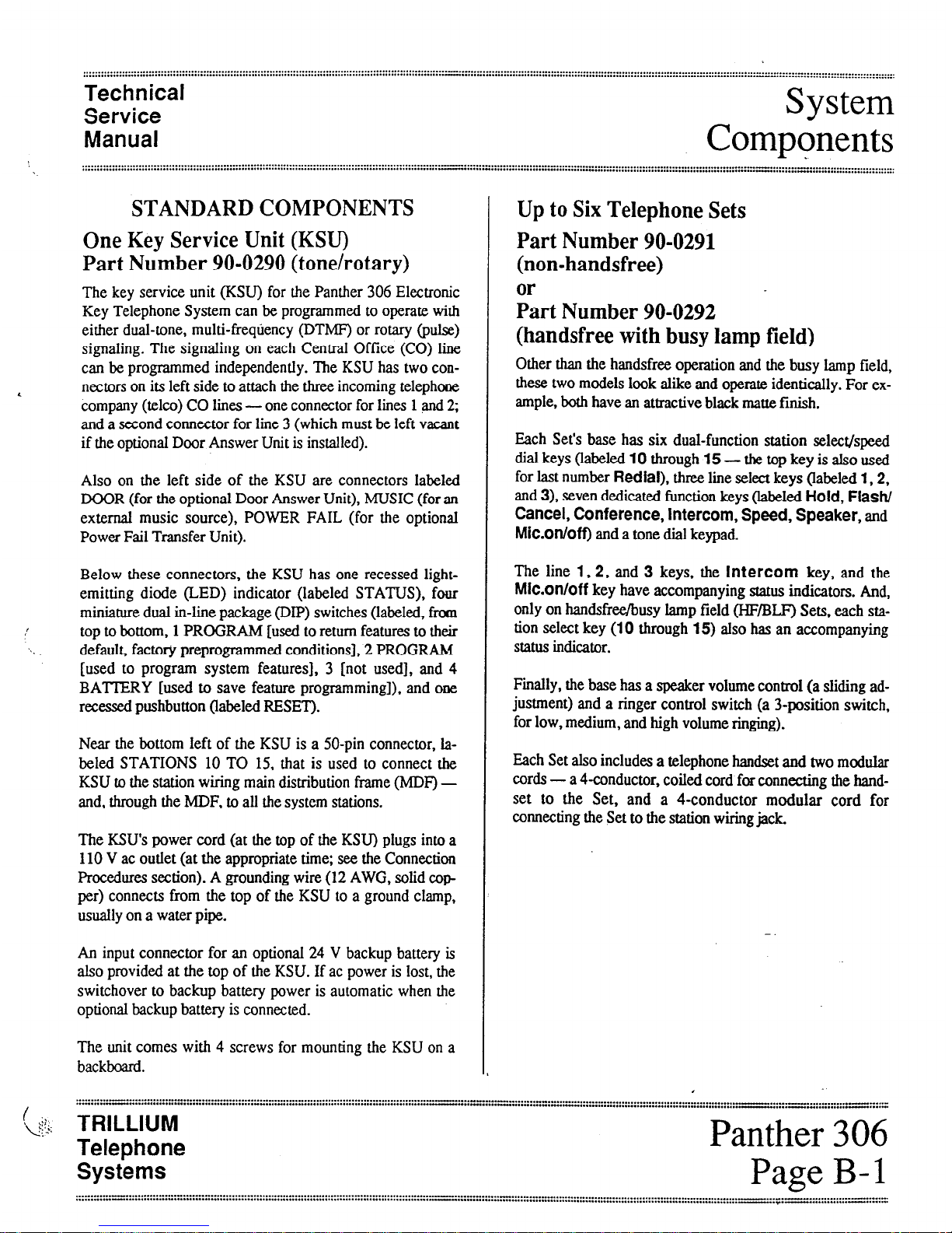
STANDARD COMPONENTS
One Key Service Unit (KSU)
Part Number 90-0290(tone/rotary)
The key service unit (KSU) for the Panther 306 Electronic
Key Telephone System can be programmed to operate with
either dual-tone, multi-frequency (DTMF) or rotary (pulse)
signaling. The signaling on each Central Office (CO) line
can be programmed independently. The KSU has two con-
nectors on its left side to attach the three incoming telephone
company (telco) CO lines - one connector for lines 1and 2;
and a second connector for line 3 (which must be left vacant
if the optional Door Answer Unit is installed).
Also on the left side of the KSU are connectors labeled
DOOR (for the optional Door Answer Unit), MUSIC (for an
external music source), POWER FAIL (for the optional
Power Fail Transfer Unit).
Below these connectors, the KSU has one recessed light-
emitting diode (LED) indicator (labeled STATUS), four
miniature dual m-line package (DIP) switches (labeled, from
top to bottom, 1 PROGRAM [used to return features to their
default, factory preprogrammed conditions], 2 PROGRAM
[used to program system features], 3 [not used], and 4
BATIERY [used to save feature programming]), and one
recessedpushbutton (labeled RESET).
Near the bottom left of the KSU is a 50-pin connector, la-
beled STATIONS 10 TO 15, that is used to connect the
KSU to the station wiring main distribution frame (MDF) -
and, through the h4DF, to all the system stations.
The KSU’spower cord (at the top of the KSU) plugs into a
110 V ac outlet (at the appropriate time; see the Connection
Procedures section). A grounding wire (12 AWG, solid cop
per) connects from the top of the KSU to a ground clamp,
usually on a water pipe.
An input connector for an optional 24 V backup battery is
also provided at the top of the KSU. If ac power is lost, the
switchover to backup battery power is automatic when the
optional backup battery is connected.
Up to Six TelephoneSets
Part Number 90-0291
(non-handsfree)
k-t Number 90-0292
(handsfreewith busylamp field)
Other than the handsfree operation and the busy lamp field,
these two models look alike and operate identically. For ex-
ample, both have an attractive black matte finish.
Each Set’sbase has six dual-function station select/speed
dial keys (labeled 10 through 15 - the top key is also used
for last number &dial), three line select keys (labeled 1,2,
and 3), seven dedicated function keys (labeled Hold, Flash/
Cancel, Conference, Intercom, Speed, Speaker, and
Mic.on/off) and a tone dial keypad
The line 1,2, and 3 keys, the Intercom key, and the
Mic.on/off key have accompanying status indicators. And,
only on handsfree/busy lamp field (HF/BLF) Sets, each sta-
tion select key (10 through 15) also has an accompanying
status indicator.
Finally, the base has a speaker volume control (a sliding ad-
justment) and a ringer control switch (a 3-position switch,
for low, medium, and high volume ringing).
Each Set also includes a telephone handset and two modular
cords - a 4-conductor, coiled cord for connecting the hand-
set to the Set, and a 4-conductor modular cord for
connecting the Set to the station wiring jack.
The unit comes with 4 screws for mounting the KSU on a
backboard.
.
I
s<~;: TRILLIUM
Telephone
Panther 306
Systems
Page B-l
............-......................................................................................................_-........
......._...........................................................
..........“-....................................................................................................
..-.............................................................................
:::::::::::::::::.-....-.----............-----..-
-.*.- .............- ......
_.. .
. . . . . . . . . . . . . . . . . . . . . . . . . . . . . . . . . . . . . . . . . . . . . . . . . . . . . . ..-......... :::::::::::::::::::::::::::::::::::::::::::::::::::::::::::::::::::::::::::::::::::::~:::::::~~:.~ :::: ::I’:.-
. . . . . . . . . . . . . . . . . . . . . . . . . . . . . . . . . . . . . . . . i . . . . . . . . . . . . . . . . . . . . . . . . . -.:::-““:~::::::I:::::::::::::::::::::::::::::::::::~::::::::::::::::::
System
Technical
Components
Service I’
Manual
..._....................................................::::::::~::::::::::::::::::::::::::::::::::::::::::::::::::::::::::::::::::::::::::::::::~~:::::~:~::::~::::::::
.....................................”...............
~:::~:::::::~::::::::::::::::::::::::::::::::::::::::::::::::::::
c
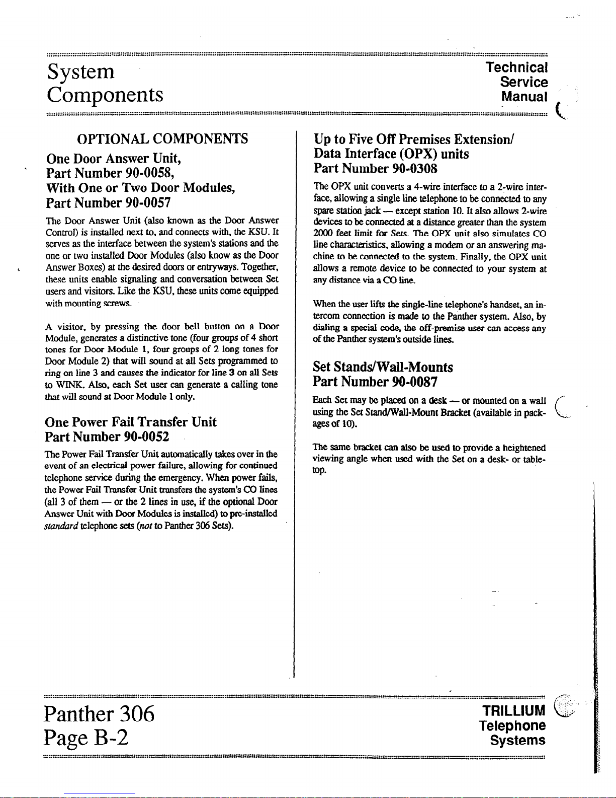
OPTIONAL COMPONENTS
OneDoor Answer Unit,
. Part Number 90-0058,
With Oneor Two Door Modules,
Part Number 90-0057
The Door Answer Unit (also known as the Door Answer
Control) is installed next to, and connects with, the KSU. It
servesas the interface between the system’sstations and the
one or two installed Door Modules (also know as the Door
< Answer Boxes) at the desired doors or entryways. Together,
these units enable signaling and conversation between Set
usersand visitors. Like the KSU, these units come equipped
with mounting screws.
A visitor, by pressing the door bell button on a Door
Module, generates a distinctive tone (four groups of 4 short
tones for Door Module 1, four groups of 2 long tones for
Door Module 2) that wilI sound at all Sets programmed to
ring on line 3 and causes the indicator for line 3 on all Sets
to WINK. Also, each Set user can generate a calling tone
that will sound at Door Module 1 only.
OnePower Fail Transfer Unit
Part Number 90-0052
The Power Fail Transfer Unit automaticalIy takes over in the
event of an electrical power failure, allowing for continued
telephone service during the emergency. When power fails,
the Power Fail Transfer Unit transfers the system’sCO lines
(all 3 of them - or the 2 lines in use, if the optional Door
Answer Unit with Door Modules is instaUed) to pre-installed
standard telephone sets(nor to Panther 306 Sets).
Up to Five Off PremisesExtension/
Data Interface (OPX) units
Part Number 90-0308
The OPX unit convertS a 4-wire interface to a 2-wire inter-
face, allowing a single line telephone to be connected to any
spare station jack -except station 10. It also allows 2-wire
devices to be connected at a distance greater than the system
2000 feet limit for Sets. The OPX unit also simulates CO
line characteristics, allowing a modern or an answering ma-
chine to be connected to the system. Finally. the OPX unit
allows a remote device to be connected to your system at
anydistanceviaaCOline.
When the user lifts the singleline telephone’shandset, an in-
tercom connection is made to the Panther system. Also, by
dialing a special code, the off-premise user can access any
of the Panther system’soutside limes.
SetStands/Wall-Mounts
Part Number 90-0087
Each Set may be placed on a desk - or mounted on a wall
using the Set Stand/Wall-Mount Bracket (available in pack-
agesof 10).
The same bracket can also be used to provide a heightened
viewing angle when used with the Set on a desk- or table-
top*
..................................--
................................-
:::::::::::::-~:::::::::-‘:::::~~~:::;:::::::~~~~::~~.-~~”~:~::~“~:~:~.--.‘-“-‘“.~--
__I-...-“”..-. “.~.....__:::::n:~“-........--”
_I.“...“.....“.......
,::-
::c
Panther 306 TRILLIUMi;$‘.;;’
c
Page B-2
Telephone
Systems

Technical
Service
System
Manual
! Components
.......................................................................
.
.
.............
........................................................................a.
........................................................................................................................
............::::::::::::~:::::~:::::::::::::::::::::::::::::::::::::::::~::::;
‘..
Designation Cards
Part Number 90-0296
(for non-handsfree Sets)
Lrt Number 90-0297
(for handsfreelbusjl lamp field Sets)
Designation Cards are used to list the first five private spe43d
call numbers and identify the assignment or location of the
< six system stations.
Although each Set comes equipped with one installed and
one spare Designation Card, you may order additional cards
(in packages of 10) for your system.
Notice
that e&h type of Set uses a
different
Designation
FacePlates
Part Number 70-0211
(for non-handsfreeSets)
&-t Number 70-0212 -
(for handsfree/busylamp field Sets)
Face Plates cover and protect the Designation Cards. You
may order spare Face Plates for your system.
Notice that each type of Set usesa
diJkrenf
Face Plate.
TRILLIUM
Telephone
Systems
Panther 306
Page B-3
cal
Technical
Service
Techni
Manual
L Specifications
.
::::::::::::::::::::::::::::::::::::::::::A.,..........................-........,.........-.........-....
............................-..................-................:::““:::::::::::::::::::::::::::::::::::::::::::::::::::::::::::::::
::::::::::::::::::::::::::::::::=:::
;:::::::.::::
::::::::::::::::::::::::::::::::::::
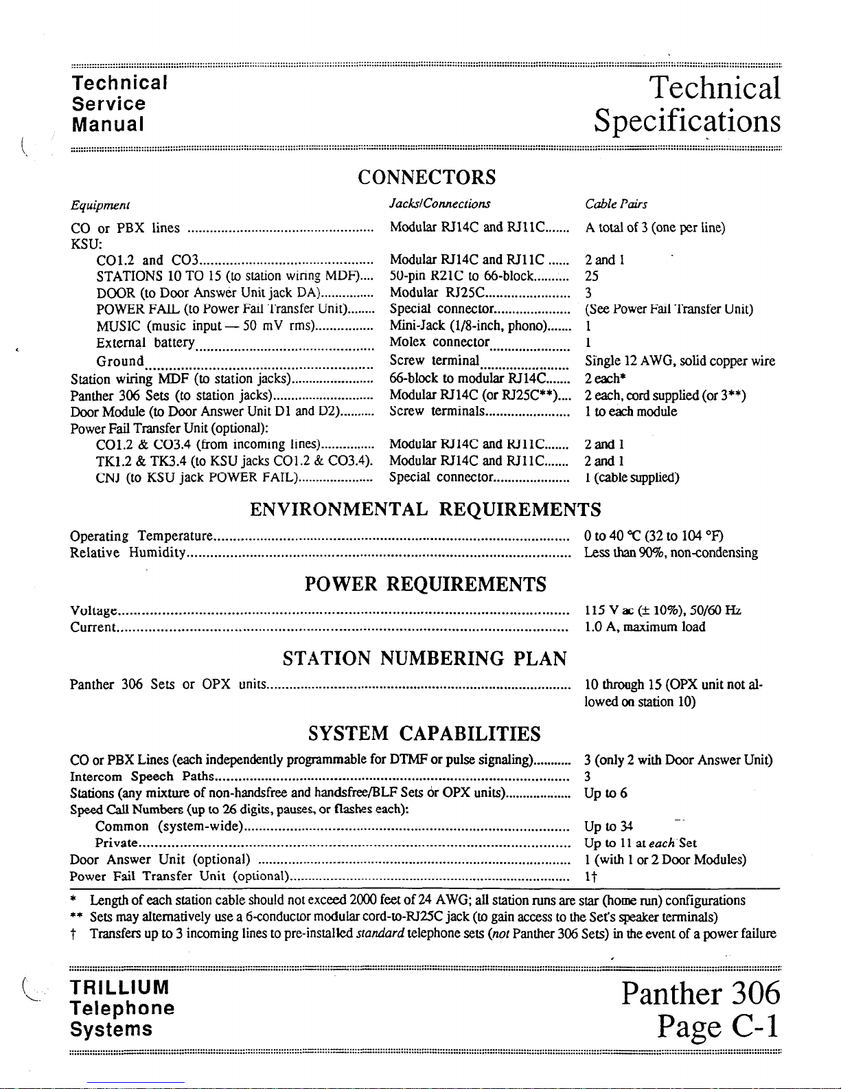
Equipment
CONNECTORS
JackslConnections Cable Ptis
CO or PBX lines ..................................................
KSU:
C01.2 and CO3 ......................................-.......
STATIONS 10 TO 15 (to station wiring MDF)....
DOOR (to Door Answer Unit jack DA) ...............
POWER FAIL (to Power Fail Transfer Unit) ........
MUSIC (music input - 50 mV rms)................
< External battery ......................................-........
Ground ..........................................................
Station wiring MDF (to station jacks) .......................
Panther 306 Sets (to station jacks) ..........._......._........
Door Module (to Door Answer Unit Dl and D2) ._........
Power Fail Transfer Unit (optional):
C01.2 & C03.4 (from incoming lines).....__........
TK1.2 & TK3.4 (to KSU jacks C01.2 & C03.4).
CNJ (to KSU jack POWER FAIL) ...._......._........
Modular RJ14C and RJllC ....... A total of 3 (one per line)
Modular RJ14C and RJllC ......
50-pin R21C to 66-block.. ........
Modular RJ25C.. .....................
Special connector.. ...................
Mini-Jack (1/8-&h, phono). ......
Molex connector ......................
Screw terminal ........................
66-block to modular RJ14C.. .....
Modular RJ14C (or RJ25C**) ....
Screw terminals.. .....................
Modular RJ14C and RJllC.. .....
Modular RJ14C and RJllC.. .....
SpeciaI connector.. ...................
2andl -
25
3
(See Power Fail Transfer Unit)
1
1
Single 12 AWG, solid copper wire
2 each*
2 each, cord supplied (or 3**)
1 toeachmodule
2andl
2andl
1(cable supplied)
ENVIRONMENTAL REQUIREMENTS
Operating Temperature ................................--.......................................................... 0 to 40 “C (32 to 104 “I!)
Relative Humidity ......................................--.......................................................... Less than !9t?%,non-condensing
POWER REQUIREMENTS
Voltage .....................................................---........................................................ 115 V ac (* 10%). 50/60 Hz
Current ................................................-......--....................................................... 1.0 A, maximum load
STATION NUMBERING PLAN
Panther 306 Sets or OPX units ..................---.....-...................................................... 10 through 15 (OPX unit not al-
lowed on station 10)
SYSTEM CAPABILITIES
CO or PBX Lines (each independently programmable for DTMF or pulse signaling) ........... 3 (only 2 with Door Answer Unit)
Intercom Speech Paths ............................................................................................ 3
Stations (any mixture of non-handsfree and handsfree/BLF Sets or OPX units). .................. Up to 6
Speed CaU Numbers (up to 26 digits, pauses,or flashes each):
Common (system-wide) .................................................................................... Upto -.
Private ........................................................................................................... Up to 11 at eachSet
Door Answer Unit (optional) ................................................................................... 1 (with 1or 2 Door Modules)
Power Fail Transfer Unit (optional) ........................................................................... 1-t
* Length of each station cable should not exceed 2000 feet of 24 AWG; all station runs are star (horae run) configurations
** Setsmay ahernatively use a 6-conductor modular cord-to-RI25C jack (to gain accessto the Set’sspeaker terminals)
t Transfers up to 3 incoming lines to pre-installed
standard
telephone sets
(not
Panther 306 Sets) in the event of a power failure
TRILLIUM
Telephone
Systems
Panther 306
Page C-l

. . . . . . . . . . . . . . . . . . . . . . . . . . z ::::;::::::::: :::::::: :::: :::::::::::::::::::::::::::::::::::::::::::::::::::::~:::::::::::::::::::::::::::::::::::::::::::::::::::::::::::::::::::::::.~::::::::::::::::::::::::::::::::::::::::::.:~::....-........ . . . . . . . . . . . . . . . . . . . . . . . . . . . . .
,. . . . . . . . . . . . . . . . . . . . . . . . . . . . . . *a . . . . . . . . . . . . . . . . . . . . . .
Technical
Service
Connection
Manual
Procedures
..............._.........._
.._.._.................................................................................................................................
,.................-.........................................................................................
..........a.
..............“.......................................................................*..................#............................................................-................................................“...I
....,.........,...........,.......,..,
STEP 1
INSTALLING THE KSU
Site Preparation
Because the KSU is at the heart of the operation of the
Panther 306 Electronic Key Telephone System, ensure that
its installation site meets the following criteria:
l
Clean, dry, and well ventilated (should meet the en-
vironmental requirements listed in Section C)
. Within seven feet of the incoming CO, CENTREX,
or PBX line terminations
WARNING
If you are in area subject to power transients,
instali a surge protector on the dedicated outlet.
. Within five feet of a dedicufed 110 V ac, 60 Hz, 3-
wire grounded outlet - an outlet that is not on a
wall switch
. Not too distant from station terminations (the maxi-
mum distance to each station is 2000 feet, using 24
AWG wiring)
. A 30” by 30” area of wall space should be reserved,
allowing room for the Power Fail Transfer Unit and
Door Answer Unit (whether they are being installed
now or might be in the future)
Backboard Installation
If the KSU is to be mounted on a concrete or masonry wall,
the use of a l&inch thick plywood backboard (30 inches
square) isrecommended.
Depending on the wall’sconstruction and your method of in-
stalling the backboard, you might need screwdrivers
(various kinds and sizes), drills and bits (various sizes), # 10
masonry screws with plastic anchors (4 of each), or l/4”
screws with wall grip screw anchors (4 of each).
Mount the backboard at least 12 inches above the floor.
SystemUncrating
a Carefully unpack the System and confirm that all
ordered parts are present by checking them off
against the Customer’s order sheet and the packing
list.
h Make sure that the customer’sfeature requirements
have been documented on a Customer Feature
Selection Form.
KSU Installation
a Mark the position of the 4 screw holes needed to
mount the KSU on the backboard.
b. Drive four screws (supplied) until their heads are
within l/g-inch of the board’ssurface.
c. Using the four keyhole slots (narrow end up) in the
side flanges of the KSU cabinet, hang the unit on
the four screws and tighten them securely.
CAUTION
Failure to properly ground the KSU may void
your Panther 306 Electronic Key Telephone
System warranty-
d Connect the ground lug at the top of the KSU to a
cold water metal pipe or ground stake, usirig copper
wire that is 12 AWG or heavier (not supplied).
Be sure that the cold water pipe’smetal continuity
is not broken by the use of plastic pipe.
Aground stake should also meet the &allation re-
quirements of your local electrical code.
e At the electrical service panel, equip the electrical
breaker for tbii outlet with alocking clip - or
mark it with a label to serve notice that this unit
should not be disconnected or shut off.
. . . .
,’
. . . . . . . . . . . . . ..-._“......“” . . . . . . . . . . . . . . . . . . . . . . . . . . . . . . . . . . . . . . . . . . . . . . . . . . . . . . . * . . . . . . . . . . . . . .
. . . . ..“....... “” . . ...““..” . . . . . . . . . . . . . . . . . . . . . . . . . . . . . . . . . . . . . . . . . . . . . . . . . . . . . . . . . . . . . . . . . . . . . . . . :::::::::::::::::::::::::::::::::::::::::::::::::::::~~:::: :::“:: zv::.“.I”::zFG :::::“:::: rG:“.*y*wz :::: _~ ::“:: ““& ::::::“::::;
.. TRILLIUM
Telephone
Panther 306
Systems
Page D-l
...............a”““.................................................................................
”..........”__“_“.....................,..................................s..................
::::::::::::::::::::::::::‘;:::::::::::~::::::::::::~~::~:::::~~:::‘~~::::~::::::::::::“:::::::~::::::~:::::::::::::::::::::::
Table of contents
Other Trillium Telephone manuals

Trillium
Trillium Talk To 308 User guide

Trillium
Trillium Panther II 1032 User manual

Trillium
Trillium Panther 612 User manual

Trillium
Trillium Talk To 308 User manual

Trillium
Trillium Talk To 616 User manual

Trillium
Trillium Panther II 2064 Operating manual

Trillium
Trillium Panther II 820 User guide

Trillium
Trillium Panther II 820 User guide

Trillium
Trillium Talk To 616 User manual

Trillium
Trillium Talk To 1032 User manual


