Trillium Talk To 308 User manual

.
.
:.
----
>I

Table of Contents
FCC Requirements and
Warnings . . . . 2
Introduction
Preparation
,,
,,
,,
,,
,,
,.
..4
Pre-installation
Requirements . . . . . . . . 4
Installation
KSU Installation ......................................................................... 5
Station Wiring Method 1............................................................ 7
Station Wiring Method
2..
.........................................................
.7
Central Office/PABX Line Connection.. .................................. .lO
Music Input ............................................................................. 10
Paging Output
......................................................................... 10
Door Answer Option
...............................................................
1 1
Power Failure Transfer Option.. .............................................. .13
System Programming
Preparation .............................................................................. 17
Programming
Mode
................................................................ 17
Initial Programming. ................................................................ 17
Reprogramming
...................................................................... 17
Feature Programming.. ........................................................... 17
Individual Feature Programming
Hold
Recall
-
Pulse Duration
-
Flash Cancel..
................... .18
C.O./PABX
Line
....................................................................... 18
Calibrated Flash/Cancel.. .................
,.:
.................................... .18
Pause on Number
................................................................... 18
Incoming Call Only
-
By Line
............................................... 18
Outgoing Call Restriction
-
By
Station.. ................................ .19
Night Transfer and Private Lines
-
By Station ...................... .19
Flexible Ringing
-
By Station and C.O. Line
......................... 19
Operating Mode..................................................................... .19
Speed Calling
-
Common Numbers,
Programming ...............
i
........................................................... 19
Troubleshooting
._..,.,,,,,.,.,_._...,,.,.,.,.,,,.,,.,.,,,_,.,_,_._._...............
21
1

2
FCC Requirements
The Federal Communications Commission (FCC)
has established rules which permit the Trillium Telephone
Systems
TalkTo
308 Electronic Key Telephone System to
be directly connected to the telephone network. A jack
is provided by the telephone company. Jacks for this type
of customer provided equipment will not be provided on
party lines or coin lines.
If the system is malfunctioning, it may also be caus-
ing harm to the telephone network; the system should be
disconnected until the source of the problem can be deter-
mined and until repair has been made. If this is not done,
the telephone company may temporarily disconnect
service.The telephone company may make changes in its
technical operations and procedures; if such changes
affect the compatibility or use of the system, the telephone
company is required to give adequate notice of the
changes.
Service Requirements
In the event of equipment malfunction, all repairs
will be implemented by Trillium Telephone Systems. It is
the responsibility of users requiring service to report the
need for service to Trillium Telephone Systems or to one
of their authorized agents.
Company Notification
Before connecting the
TalkTo
308 Electronic Key
Telephone System to the telephone network, the telephone
company must be provided with the following:
l ‘four telephone number
l The FCC Registration Number
l The Ringer Equivalence Number
l The USOC jacks required.
The FCC Registration Number, and the Ringer
Equivalence are indicated on the System label.
The jacks for the system are:
l Lines one and two
-
RJ14C.
l Line three
-
RJllC.
Warnings
Radio Frequency Energy
The
TalkTo
308 Electronic Key Telephone System
generates and uses radio frequency energy and if not
installed and used properly, that is, in strict accordance
with manufacturer’s instructions, may cause interference
to radio and television reception. It has been type tested
and found to comply with the limits for a Class B com-
puting device in accordance with the specifications in Sub-
part I of Part 15 of FCC rules which are designed to pro-
vide reasonable protection against such interference in a
residential installation. However, there is no guarantee that
Interference will not occur in a
particular
installation If this
equipment causes interference to radio or television recep-
tion, which can be determined by unplugging the
Talk75
308 Key Service Unit (KSU), from electrical power, the user
is encouraged to try to correct the interferences by one
of the following measures:
Re-orient the receiving antenna.
Relocate
TalkTo
308 units with respect to the receiver.
Move
TalkTo
308 units away from the receiver
If necessary, the user should consult the supplier
or an experienced radio/television technician for additional
suggestions. The user may find the following booklet,
prepared by the Federal Communications Commission,
helpful: “How to Identify and Resolve Radio-TV Interference
Problems’: This booklet is available from the U.S. Govern-
ment Printing Office, Washington, DC 20402, Stock No.
004-000-00345-4.
Hearing Aid Compatibility
‘This telephone is not hearing aid-compatible as is
defined in Section 68.316 of Part 68 FCC Rules. As such,
the FCC rules prohibit the use of this telephone in the
following locations:
a) Coin telephones. All new and existing coin-operated
telephones whether located on public property or in a
semi-public location (e.g. drugstore, gas station, private
club).
b) Emergency use telephones. Telephones “provided for
emergency use” include the following:
1) Telephones in places where a person with impaired
hearing might be isolated in an emergency, including but
not limited to, elevators, automobiles, railroad or subway
tunnels, and highways.
2) Telephones specifically installed to alert emergency
authorities, including, but not limited to, police or fire
departments or medical assistance personnel.
3) Telephones needed to signal life-threatening or
emergency situations in confined settings, including, but
not limited to, rooms in hospitals, residential health care
facilities for senior citizens convalescent homes, and
prisons. A telephone is not needed to signal life-threatening
or emergency situations if an alternative means of signall-
ing such a situation is available.
c) Telephones frequently needed by the hearing impaired.
1) Any telephone on which calls may only be paid for by
credit card or other pre-arranged credit. Each such
telephone must be hearing aid-compatible unless a hear-
ing aid-compatible coin-operated telephone providing
similar services is nearby and readily available

2) Any telephone made available at the work station of a
hearing-impaired employee for use by that employee in
his or her employment duty. An employee’s “work station”
is defined as the location within a workplace where that
employee is usually found in the course of his or her
employment duties. .
3) Any telephone, including internal extensions and
telephones restricted to local calling areas, made available
for use by the public in places of business or buildings
in which visits by the public are reasonably expected.
Examples include, but are not limited to, telephones
located in lobbies of hotels or apartment buildings;
telephones in stores, which are used by patrons to order
merchandise; telephones in public transportation terminals
which are used to call taxis or to reserve rental
automobiles.
4) Any telephone in a hotel or motel room.
Provided that,
if at least ten percent of the rooms in a hotel or motel are
equipped to accommodate a hearing impaired customer,
the hotel or motel need not purchase or install a compat-
ible telephone when it replaces a telephone. A room is
equipped to accommodate a hearing impaired customer
if (1) it contains a permanently installed hearing
aid-
compatible telephone; or (2) it contains a telephone which
will accept a plug-in hearing aid-compatible handset,
which shall be provided to the hearing impaired customer
by the hotel or motel; or (3) the room contains a jack into
which a hearing aid-compatible telephone provided to the
customer by the hotel or motel may be plugged (i.e., in
addition to a permanently installed telephone which is not
hearing aid-compatible).
If fewer than ten percent of the rooms in a hotel or motel
are hearing aid-compatible, when replacing a telephone
the hotel or motel must, until the ten percent minimum is
reached: (1) replace it with a hearing aid-compatible
telephone,
or
(2) procure and maintain a plug-in hearing
aid-compatible telephone handset which it will provide to
a hearing impaired customer upon request at check-in.
5) Any telephone in the locations listed in (b) (3) in which
an alternative means of
.signalling
a life-threatening or
emergency situation is not available.
* *
*

INSTALLATION
Introduction
This manual details the procedures to install and
program the
TalkTo
308 Electronic Key Telephone System.
A section on Troubleshooting is also included.
Installation is easy, and can be carried out by a cer-
tified installer, using standard cable runs and modular
jacks; or if so desired by the end-user, using standard
modular telephone line cords, extension cords, and
adapters.
Preparation
The installer should ensure that the area chosen
to mount the KSU is:
l
Clean, dry and well ventilated. The temperature should
be between
0’
and
40%
(32O
and
104OF).
The relative
humidity should be 90% or less, and be non-condensing,
*
Within seven feet of the C.O./PABX line terminations.
*
Within close proximity to the station terminations (in the
case where outdated equipment is being replaced). The
distance to each station is limited to a maximum of 2000
feet (609 meters) when 24 AWG wire is used.
0
Within five feet (1.5 meters) of a
11OV
ac
60Hz
three-
wire dedicated
unswitched
power outlet.
Station wiring should be standard two pair twisted
communication cable, 24 AWG. It is assumed that the
C.O. lines are terminated at RJ style modular jacks.
Pre4nstallation Requirements
Unpack the system and check that all items con-
form to the list of parts ordered. Make sure that the
customer’s feature requirements have been documented
on a Customer Feature Selection form.
Description
TalkTo
308 Key Service Unit
(KSU) (DTMF)
TalkTo
308 Key Service Unit
(KSU) (Rotary or
DTMF)
TalkTo
308 Set
TalkTo
308
Set (Handsfree)
TalkTo
Door Answer Unit
TalkTo
Door Module
TalkTo
Power Fail Transfer Unit
Part Number
90-0048
go-0053
90-0055
go-0049
go-0057
90-0058
go-0052
If the Key Service Unit (KSU) is to be mounted on
a concrete or masonry wall, a plywood backboard should
be provided.
-
It is recommended that a surge protector be pro-
vided for the dedicated power outlet. A suitable device is
the
TII
Model.428 plug-in protector or equivalent.
The
TalkTo
308 Set is intended for desk or table
use, but can be wall mounted using a special bracket
available as an option.
The Key Service Unit (KSU) is contained in a metal
cabinet and should be wall mounted.
The Door Answer Module is
moulded
in plastic,
measures 4 inches x 5 inches, and is fitted at the door
requiring intercom service.
4

INSTALLATION
KSU Installation
The KSU contains no user adjustable controls or
parts. All switches used during programming are acces-
si ble at the exterior of the KSU. An indicator on the left
side of the KSU flashes when the system is up and
running..
The Door Answer Unit measures 6.25 inches x 8
inches and should be wall mounted adjacent to the
KSU.
The Power Fail Transfer Unit measures 3.5 inches x
4.5 inches and should be wall mounted adjacent to
the KSU.
***
Installation
The MkTo 308 System is easily installed using the
following procedures:
l
KSU installation
l
Station Wiring (2 methods)
l Music Input,
l Paging Output
l Door Answer Option
l
Power Fail Transfer Option
The
11OV
ac three-wire outlet should be
dedicated to the KSU. At the service panel, the elec-
trical breaker for this outlet should be equipped with a lock-
ing clip, or marked with label, to prevent accidental shut-
down of the system. A surge protector should be install-
ed at the 11 OV ac outlet,
A suitable unit is the TII Model 428, plug-in power
line surge protector. Install the protector in accordance with
the manufacturer’s instructions.
The KSU is intended for wall mounting only. If a
backboard is to be used, start the KSU installation by
mounting the backboard on the wall. Then:
l
Mark the position of the four KSU mounting screws on
the backboard.
l Drive in four screws (supplied with the KSU) to within
l/8
inch of the board surface.
l
Using the four keyhole slots in the KSU cabinet, hang
the unit on the four screws.
l
Tighten the screws to secure the KSU to the backboard
Connect the ground lug of the KSU, to a metal cold
water pipe or ground stake, using 12 AWG
(2.64mm
diameter) or heavier, copper wire. If a cold water pipe is
used, ensure that the continuity to ground is not broken
by the use of plastic pipe. If a ground stake is used for
this purpose, it must be properly installed in accordance
with the local electrical code.
Caution: Failure to properly ground the KSU may
affect the system warranty.
Carry out a preliminary check of the KSU opera-
tion as follows:
l Set the switch, Battery, to On.
l Set the Switches, Program
1
and 2, to Off.
l Connect the KSU power cord to the surge protector
previously installed at the
11OV
ac power outlet.
l Status indicator lamp should flash.. ,
This indicates that the KSU is operative
To prevent accidental damage to the KSU while the
system wiring is being installed, remove the power from
the KSU as follows:
l Set the switch, Battery, to Off.
l Disconnect the power cord from the surge protector.
5

INSTALLATION
Program 1
Program 2
-
Not Used
-
Battery-
Status Indicator
-
Reset Push Button
-
0
E
-.
JL
I
-
12.68” (31 lmm)
/+-
11.36” (289mm) Ground Lug
/
c
Stations
10-17
-
PFUC
-
Page Out
-
Music In
-
Door
-
co 3
-
co 1.2
T&To
308
KSU Cabinet
-
Dimensions
6

INSTALLATION
<-
::
Station Wiring
-
Method 1
This method uses standard station wiring equip-
ment such as:
l 625 type four-wire jacks
l
communication cable
-
two pair, twisted, 24 AWG wire.
l
modular telephone Iine’cords. Two 625 type jacks and
one short modular line cord are required for each set to
be installed.
At the KSU location mount one jack for each station
line. Jacks should be mounted to the right of the KSU,
with jack opening facing the KSU. Leave about six to nine
inches (225mm) between the KSU cabinet and the jacks.
It is recommended that jacks be arranged neatly in a ver-
tical line.
At each location where a Set is to be installed,
mount a 625 type modular jack in a suitable position.
Run the communication cable between the KSU location
and the Set positions. Connect the cable to the 625 type
jacks, obeying color codes shown in the following Table.
Older quad type cable is shown for reference.
625 Type Quad Communication Function
Jack Cable Cable
Green Green White/Blue Voice Tip
Red Red Blue/White Voice Ring
Black Black White/Orange Data Tip
Yellow Yellow Orange/White Data Ring
At the KSU, connect the KSU station jacks to the
appropriate 625 type line jacks, using short modular line
cords.
You are now ready to connect the KSU to the
C.O./PABX lines.
Station Wiring
-
Method 2
This method uses a Proto-Tel adapter (8 RJ14
plugs to one 50 pin
amphenol
plug), a 66 Type Punch
down block, communications cable (2 pair 24 AWG),
industry standard 50 pin connectors, industry standard
25 pair cable (24 AWG), 625 type 4 wire jacks, and
modular line cords.
At the KSU, install the Proto-Tel adapter
(PM&25ST4-I)
in the station modular jacks using the
manufacturers instructions. Prepare a 25 pair cable of ap-
propriate length with a jack on the KSU end and a plug
at the S66
MI-?OR
end. (A
66Ml-50
block may be used
but requires installer cut down). Connect the 25 pair cable
at the KSU, and replace the cover of the adaptor box. Con-
nect the other end of the cable to the 66 type block. (See
Method 2Wiring Table). Run communication cable to each
station location from the 66 type block and terminate each
run with a 625 type modular jack. Install each set using
a modular line cord.
You are now ready to connect the
-KSU
to the
C.O./PABX lines.
Method 2 Wiring Table
Pin Lead
25 Pair Comm.
Line Sta.
Desig. Cable Cable
Cord No.
Colors Colors Colors
26 IVT White-Blue White-Blue Green
1
1VR Blue-White Blue-White Red
10
27 1DT White-Orange White-Orange Black
2
1DR Orange-White Orange-White Yellow
28 2VT White-Green White-Blue Green
3
2VR Green-White Blue-White Red
11
29 2DT White-Brown White-Orange Black
42DR Brown-White Orange-White Yellow
30 3VT White-Slate White-Blue Green
53VR Slate-White Blue-White Red
12
31
3DT Red-Blue White-Orange Black
6
3DR Blue-Red Orange-White Yellow
32 4VT Red-Orange White-Blue Green
7
4VR Orange-Red Blue-White Red
13
33 4DT Red-Green White-Orange Black
a
4DR Green-Red Orange-White Yellow
34
5vr
Red-Brown White-Blue Green
95VR Brown-Red Blue-White Red
14
35 5DT Red-Slate White-Orange Black
10 5DR Slate-Red Orange-White Yellow
36 6VT Black-Blue White-Blue Green
11
6VR Blue-Black Blue-White Red
15
37 6DT Black-Orange White-Orange Black
12
6DR Orange-Black Orange-White Yellow
38 7VT Black-Green White-Blue Green
13 7VR Green-Black Blue-White Red
16
39 7DT Black-Brown White-Orange Black
14
7DR Brown-Black Orange-White Yellow
40 8VT Black-Slate White-Blue Green
15
8VR -Slate-Black Blue-White Red
17
41
8DT Yellow-Blue White-Orange Black
16 8DR Blue-Yellow Orange-White Yellow
VT Voice Tip VR: Voice Ring
DT!
Data Tip
DR: Data Ring
Typical 625 type jack showing wiring connections.

INSTALLATION
Gnd
308 KSU
1 IOV AC
o-
0
T I I 428
Pwr
Jack
STA
17
STA
17
6
Stations Total
6
Stations Total
STA
10
Plug
Plug 4 Conductor
Modular Line Cords
Surge ProtectorSurge Protector
#12
AWG
l%
Metal Cold Water PipeMetal Cold Water Pipe
4 Conductor4 Conductor
1
0
0 2Pair 625 625 Type Type Jack Jack
Communication Cable
T
4
Conductor
Modular Line Cord
Supplied with Set
TalkTo
Set
Jacks
C.O./PABX Lines
System Wiring
-
Method 1
a

INSTALLATION
25 Pair Cable
Gnd
#I2
AWG
Proto
Tel
PM8-25ST4-
I
\
308 KSU
P\n
irir
11OV
AC
0’
0
Tit
428
S66-MI-50R
Block
STA 10STA 10
JackJack
Plug
4 Wire Modular Line Cords
..ie
Metal Cold Water Pipe
Surge Protector
Plug
1
2 Pair Communication Cable
8
625 Type Jack
Plug
K----.
Plug
8
7
625 Type Jacks
3
Supplied with Set
TalkTo
Set
6 Stations Total
C.O./PABX Lines
System Wiring
-
Method 2
9

INSTALLATION
Central Off ice/PABX Line Connection
These lines are normally terminated by
RJllC
type
jacks. When requesting service from the telephone com-
pany, please request that the first two lines are terminated
with an
RJ14C
type jack. Alternatively, if the lines are
already installed using
RJllC
type jacks, an adapter such
as an
SE 2678
(Suttle Apparatus Corp.) will be required.
Where the connection is made directly from the CO.
line 625 type jack to the KSU, use a four conductor
modular line cord.
Where the connection is made using the splitter
adapter (SE
2678)
the connections from the 625 type CO.
line jacks to the adapter are made using modular line
cords. The connection from the adapter to the KSU is
made using a modular telephone extension cord (female
to male).
Music Input
The
TalkTo
308 System provides both music on hold
(MOH) and background music if an external music source
is provided. This music source is connected via the Music
In
jack on the KSU with a
l/8
inch miniature plug. The
KSU requires a music signal not exceeding 50mV rms.
Paging Output
The
TalkTo
308 System provides external
loudspeaker paging by the stations through the
Page
Out
jack. The voice output from the KSU to the customer pro-
vided external amplifier is connected with a
118
inch
miniature plug. The output is
2QOmV
rms at 600 ohm
impedance.
Page Out
Music In
Paging Amplifier
Mon
118
Mini Plugs
50mV
II
308 KSU
Music Source
Music and Paging Connections
10

INSTALLATION
Door Answer Option
The
TalkTo
308 System will provide door signaling
and 2 way conversation with up to 2 doors. To provide this
option, one door answer unit and a maximum of 2 door
modules are required.
The Door Answer Module is
moulded
in plastic,
measures 4 inches x 5 inches, and is fitted at the door
requiring intercom service.
Door
308 KSU
Plug
I I I
3.89”
(99mm)
1.57” (40mm)
I
*
I_1
Mount each of the door modules adjacent to the
door to be equipped with intercom service. The door
module consists of 2 pieces, the base and the electronics
unit. To separate the base from the electronics unit, remove
one screw at the bottom front face. Mount the base on
the wall or on an electrical outlet box using the screws
provided.
Door Answer Unit
6 Conductor Telephone Line Cord
(Supplied with Door Answer Option)
Cable
Door Module 1
Door Module 2
Door Answer Option Connections

INSTALLATION
1’
t---6.26”
(lSSmm)-----rJ
The Door Answer Module with front cover
Jetached
showing the two screw terminals.
Door Answer Unit
The Door Answer Unit (DAU) is mounted on the
backboard with the screws supplied. The Door Answer
Unit is connected with a modular 6 conductor cord sup-
plied with the Unit. At the KSU plug the 6 conductor cord
into the jack labeled
Door.
At the Door Answer Unit, plug
the cord into the jack labeled DA.
I
)--5.78”
(147mm)-+
I
Caution: If the Door Answer Unit is connected it
replaces the third C. O./PABX line; therefore with the
door option installed the system will only accom-
modate 2
C.O./PABX
lines. Do not use jack C.0.3.
Run 2 conductor cable from the Door Answer Unit
to each of the door modules. Connect the wires under the
screw terminals at each end. At the Door Answer Unit,
Door
7
connects to
D7
terminals and Door 2 connects
to
02
terminals. After connecting the 2 wires at the door
module, replace the electronics unit in the base.
Door Answer Unit
-
Dimensions
12
INSTALLATION
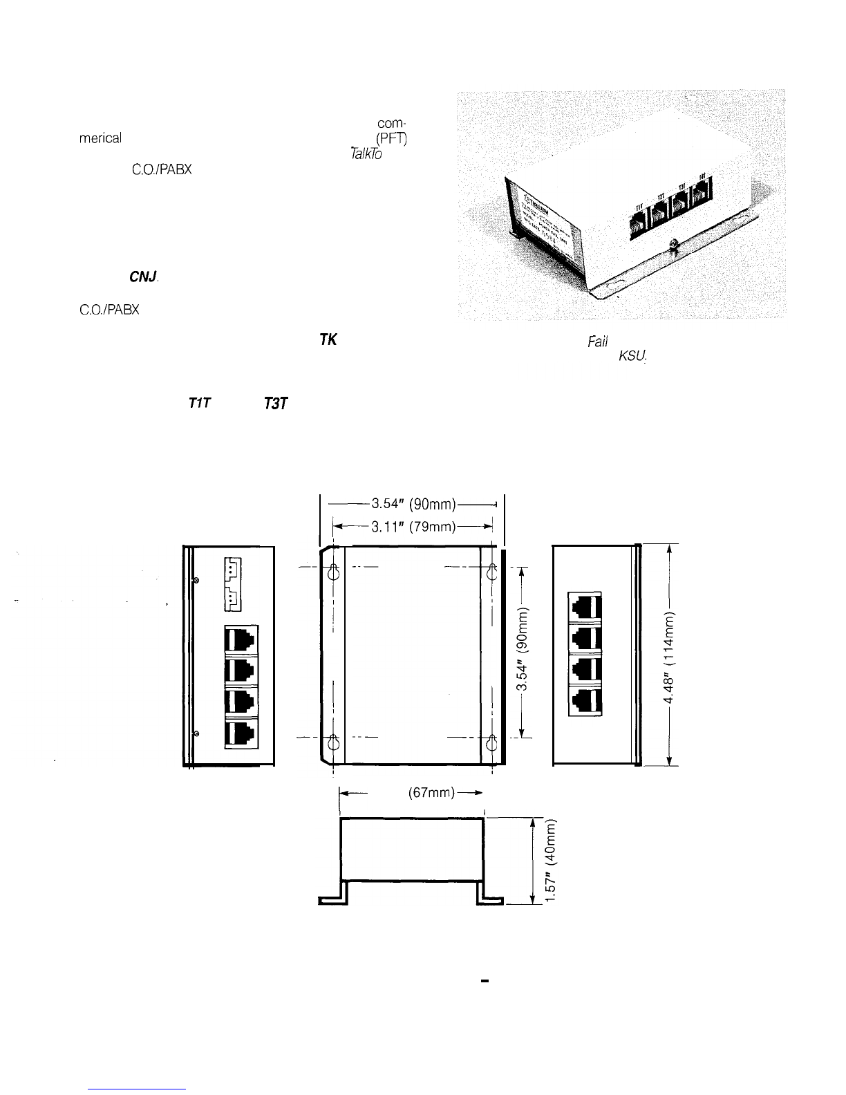
Power Failure Transfer Option
To provide Telephone service in the event of a com-
merical power outage, a Power Failure Transfer Unit (PFT)
must be installed. The PFT will allow all 3 of the
TalkTo
308
system’s C.O./PABX lines to be transferred to 3 individual
industry standard 2 wire telephones when the commer-
cial power fails.
Mount the PFT unit on the backboard near the
KSU. Install the 2 conductor special cable supplied with
the unit. At the KSU, plug one end into the jack marked
PFUC. At the PFT unit, plug the other end into the jack
marked
CNJ.
Using 4 conductor modular line cords, connect the
C.O./PABX lines to the jacks marked CO 1.2, CO 3.4 on
the PFT unit. Connect the PFT line outputs to the KSU us-
ing two 4 conductor modular line cords.
TK
1.2 on PFT
to CO 7.2 on KSU and
TK
3.4 on PFT to CO 3 on KSU.
Mount up to 3 industry standard 2 wire telephone
sets in convenient locations and connect each of them to
the jacks marked
T7T
through
T3T
on the PFT unit.
The system is now ready for programming.
The Power
Fail
Transfer Unit should be wall
mounted
adjacent to
the
KS?.
-3.54”
(90mm)-
k3.11”
(79mm)4
II
t-
2.63”
(67mm)-
Power Fail Transfer Unit
-
Dimensions
13

INSTALLATION
PFU
co 3
co 1.2
308
KSU
Cable Supplied with Power Fail Unit
/
D
J
Plug
I3
RJ 4 Wire Modular Line Cord
Plug
Plug
c
I
IY
L
q
CNJ
T4T
TK 3.4
T3T
TK 1.2
T2T
co 3.4 TIT
co 1.2
Power Fail Transfer Unit
625
Type Jacks
C.O.IPAB;
Linesq
Not Used
q -w Maximum
1
0-p
Per incoming Line
P
Power Fail Telephone
Power Fail Transfer Option Connections
System Programming
Before programming the system, check that the
It is recommended that the system is programmed
customer has completed a Features
Selection
form. Aimmediately following installation. Programming makes use
copy of the form and instructions for feature selection is of station 10 dial pad, keys and indicator lamps when enter-
included in this section. ing selected feature parameters.
14

SYSTEM PROGRAMMING
System Requirements for Programming
For the system to be programmed to meet your re-
quirements, it is necessary to decide what features are
needed, and what parameters are required for those
features selected. The following notes are intended to aid
you in choosing the correct features and parameters. For
reference purposes, please complete the accompanying
programming form.
(1) Hold Recall Time: Determines the time period
between putting a caller on hold and receiving a tone
reminder that the caller is still on hold. Periods are 1 minute,
2 minutes, 3 minutes or no hold recall.
(2) Tone Duration:
This sets the time duration for each
dialed DTMF tone. Can be
55ms
or 75ms.
(3) Flash/Cancel:
Which function is the flash/cancel key
to have? There are four calibrated periods
-2250ms,
500ms,
1 sec., or 3
sets.
to choose from.
(4) Pause on Number:
Allows an automatic pause to be
inserted into speed called numbers. Used when the
system is behind a PABX, and it is necessary to wait a
short period of time for C.O. dial tone to be returned,
Pause can be inserted after the digit 7, 8, 9 or 0.
(5) C.O./PABX Line:
Used to tell the system whether the
lines are CO. or PABX types.
(6) Incoming Call Only By Line: Allows individual
C.O./PABX lines to be restricted to incoming calls only.
Restriction is system wide.
(7)
Outgoing Call Restriction By
Stu:ion:
Allows indi-
vidual stations to be restricted for toll and outgoing calls.
There are three classes of service: A, B or C.
l Class A: No restriction.
l Class B
-
C.O. Line: Dialing 0 + a number, 1 + a
number or dialing more than 8 digits, is restricted.
l Class B
-
PABX Line:
Dialing C.O. line access code
+0 + a number, CO. line access code + 1 + a number,
or CO. line access code + more than 8 digits, is restricted.
l
Class
C: Calling is restricted to other stations connected
to the system. No outside access at all.
If class B is selected private speed call numbers are
restricted, common speed call numbers are not.
(8) Night Transfer: Allows ringing to be assigned to
selected stations when the system is put into a night transfer
mode. At least one station must be selected, if night transfer
is to be used.
(9) Private Line: Allows line 1 to be assigned to a
designated station as a private line. Other stations do not
have access to the assigned
C.O./PABX
line.
(10) Flexible Ringing Assignment:
Allows ringing to be
assigned by C.O. line at selected stations. Note that if CO.
line 1 is assigned as a private line to a designated station,
ringing will be heard, at that station irrespective of whether
ringing is assigned or not.
(11) Door Answering:
If the door option is equipped, CO.
line 3 is always associated with door answering, and can-
not be used as a C.O./PABX line.
Station List.
Speed Calling List
Yi
Ringer Control
A
Designation Card
w
Volume Control
Tone Dial
Pad’
/
Conference
A
Microphone on/off
-
Direct Station Select (DSS) Keys
Speed Call Keys
I
Hold
TalkTo
368 Set keys and switch layout.

SYSTEM PROGRAMMING
Customer Feature Selection
Hold Recall
(l)*
*Select
ok
item per Line
1 min
IJ
L
min
0
3 min
0
No Recall Cl
Tone Duration
(2)*
I
55ms
a
75ms
0
Flash/Cancel (3)
*
Flash
0
250
ms
0
500ms
0
1
set
0
3
set
0
Cancel
GT
500ms is recommended for calibrated flash
Pause on Number (4)
Yes
0
70809000
No
F
C.O./PABX LINE (5)
C.O.
u
1
Liz
p-3
c
PABX
0
102030
Incoming Call Only By Line (6)
Yes
0
No
I2
Line 1
c3
Line 2
0
Line 3 Cl
Outgoing Call Restriction
By Station (7)
StnKlass
Yes
I3
mi
11111
r;T;n
W]
No
0
Night Transfer (8)
Yes
0
stn#
q q q q
No
W
q
mmm
Private Lines (9)
;
Yes
EC!
No
0
Flexible Ringing (10)
Yes
0
%/Line
lTT-rr.mm
telephone systems
Should you require service, please calf the following number:
16

SYSTEM PROGRAMMING
Preparation
-
Before attempting to program the system, check
l
Station 10 is connected.
l The switches, Program
7
and 2, are set of Off.
l The KSU is connected to a
1lOV
ac power supply.
l The status
hdicator’on
the KSU is flashing.
l The switch, Battery, is set to On.
l
A Features Selection form, completed by the customer,
is available.
Note:
Default data is automatically loaded as feature pro-
gramming if the switches, Program
7
and Program 2,
are set to
On,
and the
Reset
button is pressed. The default
states are shown in the Feature Programming Tables.
Programming Mode
Caution:
If
the system is a/ready in use and is to be
reprogrammed, the following operations should be
carried out at a low traffic period. The’system can-
not be used during programming.
‘-.
Initial Programming
Feature programming is entered using station 10.
Each feature is accessed using a 3-digit code entered from
the dial pad. The status of the feature is then displayed
on the
C.O. Line
1,2,3,
and
mic. on/off
indicator lamps.
The status can be changed by pressing the key associated
with appropriate indicator lamp. In the case of the mic.
on/off
indicator, the key used is
hold.
Each access key
functions as a press on/off switch; press once, the lamp
To put the system into programming mode; at the KSU:
l
Ensure that the switch,
Battery,
is set to
On.
l Set the switches, Program 1 and Program 2 to On. turns on, press again, the lamp turns off
?
Press the
Reset
key.
l
Status Indicator lamp stops flashing.
l Set the switch, Program
7
to Off.
l
Press the Reset key.
l
Press
*
key on station 10.
l int. indicator comes on.
l System now ready to be programmed.
Reprogramming
To put the system into a reprogramming mode; at the KSU:
l
Ensure that the switch,
Battery,
is set to
On.
l Set the switch, Program 2, to On
l
Press the
Reset
key.
l
Status indicator lamps stop flashing.
l
Press
*
key on station 10.
l int. indicator comes on.
l System now ready to be reprogrammed.
Feature Programming
C.O. Line Select
1,2,3
Indicators
C.O. Line Select Keys
Hold Key
Microphone on/off
Indicator
TalkTo
308 Set
17

INDIVIDUAL FEATURE PROGRAMMING
Features need not necessarily be programmed in
a specific order. Each is accessed simply by entering the
specific 3-digit access code. The following charts show the
Feature, the Access Code the Access Keys and their
functions.
Hold Recall
-
Pulse Duration
-
Flash/Cancel
Access Code 010
Default is
-
No recall
-
75ms
-
Flash
Caiibrated Flash/Cancel
Access Code 030
Default is
-
250ms
Feature Data C.O.
7
C.O.
2
co.
3 hold
mic.
on/off
250ms Not Not
Off Off
500ms
appk-
applic- on
Off
1
second
able able
Off
on
3 seconds
on on
Note: 500ms is recommended for calibrated flash.
Pause on Number
Access Code 040
Default is
-
no pause
C.O.
2
C.O.
3 hold
mic. on/off
Feature Data C.O.
1
No Recall
Off
1 Minute on
2 Minutes
Off
3 Minutes on
Off
Off
on
on
55ms Tones
75ms Tones
(Recommended)
Flash
Cancel
Feature Data
Off
Off
on
Off
Off
3n
3ff
Off
on
Off
Off
Off
on
Off
Ofi
on
Examples
1 mrnute Recall
55ms Tones
Flash
on
Off Off
on
Off
on
1 minute Recall
75ms Tones
on
*
on
Incoming Call Only
-
By Line
Access Code 070
Default is
-
No Restriction
Off off-
C.
O./PA BX Line
Access Code 060
Default is
-
CO.
C.O.
3 hold
mic. on/off
co.
1
C.O.
2
I
Feature Data
Line 1
Unrestricted
Line 1
Restricted
Line 2
Unrestricted
Line 2
Restricted
Line 3
Unrestricted
Line 3
Restricted
Examples
Line 1
Unrestricted
Line 2
Restricted
Line 3
Unrestricted
Off
on
Cature Data
C.O. Line 1
PABX Line 1
C.O. Line 2
PABX Line 2
C.O. Line 3
PABX Line 3
Examples
Line 1
_
C.O.
Line 2 . PABX
Line 3
-
PABX
Line 1
-
C.O. _
Line 2
-
CO.
Lrne
3 . PABX
co. 1
C.O.
2
Off
on
C.O.
3
Off
on
hold
mic. on/off
Not
applicable
Off
on
A
Off
Off
Off
on
Not
applicable
Off
on
on
Off
on
on
Not
applicable
Off
Not
applicable on
18

INDIVIDUAL FEATURE PROGRAMMING
Outgoing Call
Resiric
tion, Night
Transfer and Private Lines
-
By Station
Access Code
1Xx
(where XX is station number 10-17)
Default is
-
No Restriction, No Ringing, No Private Line
Sature
Data
C.O.
1
C.O.IPABX
Line
Restrictions
Class A
No
Restrictron
Off
Class
B
-
Dialing 0 +
number
Dralrng
1
+
number
Dialing more
than 8 digits
on
Class C
-
Dialing an
outside line
Off
Nrght Transfer
No ringing
Ringing
Private Line
(only applies
to Line 1)
C.O. Line 1
No
C.O. Lrne 1
Yes- a
Examples
Station 13
Class B
Restrictions,
Night Transfer
Ringing
C.O. 1 Private
Line
Access Code
113
on
C.O.
2
Off
Off
on
Off
C.O.
3
Off
on
on
hold
mic. on/off
Off
on
on
Notes:
Class B Restrictions
-
If the line is a PABX line, the CO.
line access code is included in the restriction.
Class C Restrictions
-
If the line is a PABX line dialing
the C.O. line access code only, is restricted.
FIexible
Ridging
-
By Station and
CO.
Line
Access Code 2XX
(where XX is station number 10-17)
Default is
-
No Ring
I
=eature
Data
C.O.
1
No ranging
C.O.
2
No ringing
cm
3
No
ringrng
C.0 1 ringing
CO. 2 ringing
C.O. 3 ringing
Examples
Station 10 rungs
for C.O. 1 and
2, but not C.O.
3
Access Code
210
Station
17
rings
for C.O. 3 only
Access Code
217
C.O.
1
Off
on
on
Off
C.O.
2
Off
on
on
Off
C.O.
3
Off
on
Off
on
hold
mic. on/off
Not
applicable
Not
applicable
Operating Mode
0
p”
-e
programming has been satisfactorily completed,
tQe
ystem should be switched to its operating mode as
follows.
At the set
l
Press
#
key.
l All indicator lamps at station 10 turned off.
At the KSU
l Set the switch, Program 2, to
Off.
l
Press Reset key.
l
Indicator lamp at KSU starts to flash
The system is now ready for use.
Speed Calling
-
bubers,
Programming
A maximum of forty numbers can be programmed.
Numbers are stored against two digit access codes in the
range 20 to 59 inclusive. These numbers must be pro-
grammed from station 10. f
Before programming check that the
int.
indicator is off.
l Press the speed key.
l
int.
indicator winks slowly (My-Line).
l Internal dial tone is heard at the Set’s speaker.
l Dial the two digit access code (20 to 59).
l
int.
indicator flashes very quickly, and dial tone is turn-
ed off.
l Dial the speed call number to be programmed (Max-
imum number of digits is 16).
Other manuals for Talk To 308
1
Table of contents
Other Trillium Telephone manuals

Trillium
Trillium Panther II 820 User guide

Trillium
Trillium Panther 306 Operating manual

Trillium
Trillium Panther II 820 User guide

Trillium
Trillium Panther II 2064 Operating manual

Trillium
Trillium Talk To 1032 User guide

Trillium
Trillium Talk To 308 User guide

Trillium
Trillium Panther II User manual

Trillium
Trillium Talk To 1032 User manual

Trillium
Trillium Panther 612 User manual

Trillium
Trillium Talk To 616 User manual


