Trillium Panther 612 Operating manual

Trillium
Panther 612
Electronic Key Telephone System
Technical Service Manual

3
AtoZ KELLATRONICS, INC,
[:m:mE:f:f:f:
=7zlwER- -m’m-

I
....................................... I.. ...........................................
..................... ..“. ............ -. .......................................... -. ... --. ........
-.-.-. ......... -. ...............................
-. ................................................................................................................... .. -_.
..- ........................................ ..................................... .._.__
..-
.........................................................
Technical
Service
Table of
Manual
Contents
.........-..........................._.
.......................” ...........................................-.
...
..............-........................................
-1..
........
-.
.............................................
..--..-.............-
............................................
::::::::::::::::::::::::::::::-=:::::::::::::::::::::::::::::::
....................-I..
...”
..“.
.......
::::::::::::::::::::::::
Topic Page
Chapter Introduction
PREFACE ................................. ................................................................................................................... Intro-l
ABOUTTHlSCHAPTER
..............................................................................................................................
QUICK-REFERENCE CHART.. Intro- 1
... .......................................................................................... ..[ ....................... Intro-2
SectionA - FCC Requirements
RADIO AND TELEVISION INTERFERENCE ...................................................................................................... A-l
HEARING AID COMPATIBILITY ....................................................................................................................... A-l
RES’ONSII3ILITES .............................................................................................. ........................................... A-2
User Responsibilities .................................................................................. .................................................. A-2
Telco Responsibilities .................................................................. .................................................................. A-2
SectionB - SystemComponents
STANDARD COMPONENTS ......................................................................... ..................................................... B-l
One Key Service Unit (KSU)................................................... ........................................................................ B-l
Up to Twelve Telephone Sets.. ....................................................................................................................... B-l
OPTIONAL COMPONENTS ................................................................................ ................................................ B-2
One Door Answer Unit .................................................................................................................................. B-2
Up to Two Power Fail Transfer Units ............................................................................................................... B-2
Up to Eleven Off Premises Extension/Data Interface (OPX) units .......................... ................................................ B-2
One Station Message Detail Recorder (SMDR) Interface ..................................................................................... B-2
Set Stands/Wall-Mounts ............................................. .................................................................................... B-3
Designation Cards ............................................................................ ............................................................ B-3
Face Plates............... ..................................................................................... ............................................... B-3
SectionC - Technical Specifications
CONNECl’ORS ................................................................................................................................................. c-1
SMDR INTERFACE UN-IT (Optional) ................................................................................................................... C-l
ENVIRONMENTALREQUIREMENTS ................................................................ ................................................ c-2
POWERREQUlREMENTS .................................................................................................................................. c-2
STATION NUMBERING PLAN ........................................................................................................................... c-2
SYSTEM CAPABILITIES ................................................................................................................................... c-2
>
. . . . . . . . . . . . . . “...... . . . . . . *.** . . . . *.......- .
. . . . . . . . . . . . . . . . . . . . . . . . . . . . . . . . . . . . . . . * . . . . - . . . . . . . . . . . . . . . . . . . . . . . . . . . . . . . . . . . . . . . . . . . . . . . . . . . . . . . . . . . . . . . . . . . . . . . . . . . . . . . . ......................... * .........................................-.................................-............-.....................,....
. . . . . . . . . . . . . . . . *..a.** . . . . . . . . . . *...*...* . . . . . . . . . . . . . . . . . . . . . . . . . . . . . ..* . . . . . . . . . . . * . . . . . . . . . . . . . . . . . . . . . . . . . . . . . . . . . . . . . . .....................--..........................................-..........................
TRILLIUM I
Telephone
Panther 612
Systems
Page i
.............................................“-.............................................................................
.......................*...........................s.................s.........,........*............................................................,........................”...........“..“_”
..,....................,....................
“..”
.......,.......,.....
..................-..............................................................................................................................

Table of
Contents
Technical
Servic-
Manu :
_ ..................... ..-..- .................................................... -- ................................ . . ...............
... . ......... . . ........... -.** .................... ......... . . . ......... ....... -. ......................................... ... . . ... -. .............................................................
-. . . . ... . ..................................................... :::::::::::::::::::::::::x::“:‘-:::::::::::: :::: ‘-~:
Topic Page
SectionD - Connection Procedures
STEP 1: INSTALLlNG THE KSU ................................................................................................................... D-l
Site Preparation. ........................................................................................................................................... D-l
Backboard Installation ......................................................................................... .......................................... D-l
~~Systemunclating .......................................................................................................................................... D-l
KSU Installation ........f .................................................................................................................................. D-l
STEP 2: CONNECTING INCOMING TELEPHONE LINES ................................................................................ D-2
STEP 3: INSTALLING STATION WIRING ..................................................................................................... D-2
Station Wiring Table..................................................................................................................................... D-3
STEP 4: CONDUCTING THE INITIAL SYSTEM AND STATION TESTS........................................................... D-5
STEP 5: CONNECTING THE BACKUP BATTERY .......................................................................................... D-5
STEP 6: CONNECTING DOOR ANSWER UNIT AND DOOR MODULES ........................................................... D-6
Door Answer Unit Installation ................................................................................ ......................................... D-6
Door Module Installation ........................................................................................ ........................................ D-6
DoorAnswerUnitTest.. .................................................................. ............................................................. D-7
STEP 7: CONNECI’ING THE MUSIC SOURCE ............................................................................................... D-8
Music Connection ......................................................................................................................................... D-8
Music Test.. ........................................................................... ...................................................................... D-8 /
STEP8: CONNEC’l.ING THE EXTERNAL PAGING EQUIPMENT ..................................................................... D-9
Equipment Connection ................................................................................................................................... D-9 ’
Paging Test.. ................................................................................................................................................ D-9 /
STEP 9: CONNECTING AN EXTERNALLOUDBELL ..................................................................................... D-9
muipment Connection ................................................................................................................................... D-9
Loud Bell Test. ............................................................................................................................................. D-9
STEP lo: CONNECIING THE OPX UNlT .................................................................................................... ...
D-10
OPX Unit Connection ................................................................................................................................. D-10
OPX Unit Test............................................................................................................................................ D-10
STEP 11: CONNECTING THE SMDR INTERFACE UNIT ................................................................................. D-11
SMDR Interface Unit Installation .................................................................................................................. D-11
SMDR Interface Unit Test ........................................................................................................................... D-11
SMDR Printout Formats ............................................................................................................................... D-11
STEP 12:
CONNECl-INGTHEPOWERFAILTRAN!WERuNITS .
.. ................................................................... D-12
Power Fail Transfer Unit Installation ............................................................................................................... D-12
Power Fail Transfer Unit Test........................................................................................................................ D-13
STEP 13: INSTALLJNGANEXTERNALAMPLIFIER ...................................................................... . ............... D-14
TRILLIUM 1).
Telephone
Systems


Technical
Service
“2 Manual
Chapter
Introduction
;r ..................................
.................................-.
..................................................................................................................................................
....................................................................................
.“.
........................................................
..-
..-
................................
................................
::::::::‘-::
::::::::::::::::::::::::::::::::::
PREFACE
The Panther 612 Electronic Key Telephone System is a
state-of-the-art system that incorporates sophisticated elec-
tronics to meet ti communications needs of today’s home,
office, and small business user.
It’connects six outside telephone lines (only five if the op
tional Door Answer Unit and Door Modules are installed)
with up to twelve station Sets- which are all wired in a
star configuration Both a tone only key service unit (KSU)
and a tone/rotary KSU are available. Also, both Handsfree
and Non-Ham&free Sets are available; the Handsfree Sets
also include Busy Lamp Field (BLF) indicators that show
the status of all system stations.
Common and private speed call numbers, call transferring,
door answering (with optional Door Answer Unit and Door
Modules), internal monitoring, conferencing (up to 3 par-
ties), internal intercom paging (station-to-station, zone, and
all page paging), external loudspeaker paging, call detail and
account code recording (through an optional SMDR inter-
face unit), and last number redialing are just some of the
many features offered.
The attractive, well-designed system makes feature pro-
gramming and operation very easy. In addition, the Panther
system is designed to allow easy interfacing with modems
and answering devices through an optional OPX device.
The fully sealed Panther 612 Electronic Key Telephone
System may be installed in either a standalone mode or be-
hind a CENTREX or PBX. The microprocessor-controlled
circuitry operates all system communications and the flexi-
ble programming.
An optional external backup 24 V battery can be connected
to the system; the backup battery is automatically brought
on line in the event of a power failure, thus preventing inter- :
ruptions in telephone service.
Also, in the event of a total system failure, incoming lines
will be transferred to standard sets if optional Power
Transfer Units have been installed in the system.
>
. . . . . . . . . . . . . . . . . . . . . . . . . . . . . . . . . . . . . . . - . . . . . . . . . . . . . . . . . . . . . . . . . . . . . . . . . . . . . . . . . . . . . . . . . . . . . . . . . . . . . . . . . . . . . . . . . . . . . . . . . . ................................
. . . . . . . . . . . . . . . . . . . . . . . . . . . . . . . . **.CI . . . . . . . . . . . . . . . . . . . . . . . . . . . . . . . . . . . . . . . . . . . . . . . . . . . . . . . . . . . . . . . . . . . . . . . . . . . . . . . . . . . . . . . . . . . . . .....................................................-................................................ ” ....................... _,
. . . . . . . . . . . . . . . . . . . . . . . . . . . . . . . . . . - . . . . . . . . . . . . . . . . . . . . . . . . . . . . . . . . . . . . . . . . . . . . . . . . . . . . . . . . . . . . . . . . . . . . . . . . . . . . .
I
TRILLIUM
Telephone
Panther 612
Systems
Page Intro- 1
ABOUT THIS CHAPTER
This chapter has also been designed specifically to enable
technicians to install, operate, and maintain the Panther 612
Electronic Key Telephone System. Information is presented
in a logical order, without undue wordiness - to help the
technician find, understand, and use the relevant informa-
tion, quickly and easily.
Therefore, for example, the Connection Procedures are sep
arated into concise steps that have a logical and necessary
sequence; and reference material (Technical Specifications,
Feature Programming, Operating Instructions, and
Troubleshooting) is presented in a variety of easy-to-follow,
visible-at-a-glance tabular formats.
To acquaint yourself with this chapter, please review the
Table of Contents and spend a few moments browsing
through the different sections.
CAUTION
Panther equipment is sealed. Breaking the seal
will void your warranty.
If you have an installation, operation, or troubleshooting
problem that you cannot solve by using this chapter (and
that your dealer cannot help solve), call TRILLIUM
Customer Service at l-800-848-2444 (inside California, call
l-800422-7600).
NOTE
For your ready reference, a chart summarizing
indicator signals appears on the back of this
page.
. . . . . . . . .
. . . . . . . . . . --.~ . . . . . I .
. . I.... . . . . . ..-...............................................
. . . . . . . . . . . . . . . . . . “_...I . . . . . . . . . . . . . .. . . .. “” . . . . . - . . . . . . . . , . . ...” . . . .. . . .. .
. . . . ...” . . . . . - . . . . . . . . . . .. . . . .. . . . . . . . . . . .
. . . . . . . . . . . . “.” . . . . . .. . . . .. .
-.a . . . . - . . . . . . * . . . . . . . . . . . . . .. . . .. . *. . . . .. . . .. . . .. . . . .. . . .. . . . .. . . . . . .. . . . ..-............... k..
. . . . . . . . . . . . * . . . . . . . . . . ....” ....................................................: ..._._._....._._.. I ......:..-
. . . . . . ..-.-_..................... __._
Chapter
Technical
Introduction
Servic’ -.;
Maw j
................ ..-- ..............
...... ..-. ..... ...“. .............. -.
I..
..................................................
...........................................................................................................................................................................
. ................................ . ........................................ . .
..- ......................................... .
...
. ...:::::: “‘“~::“==: ::::::::: ::: :::::::::::::: :”
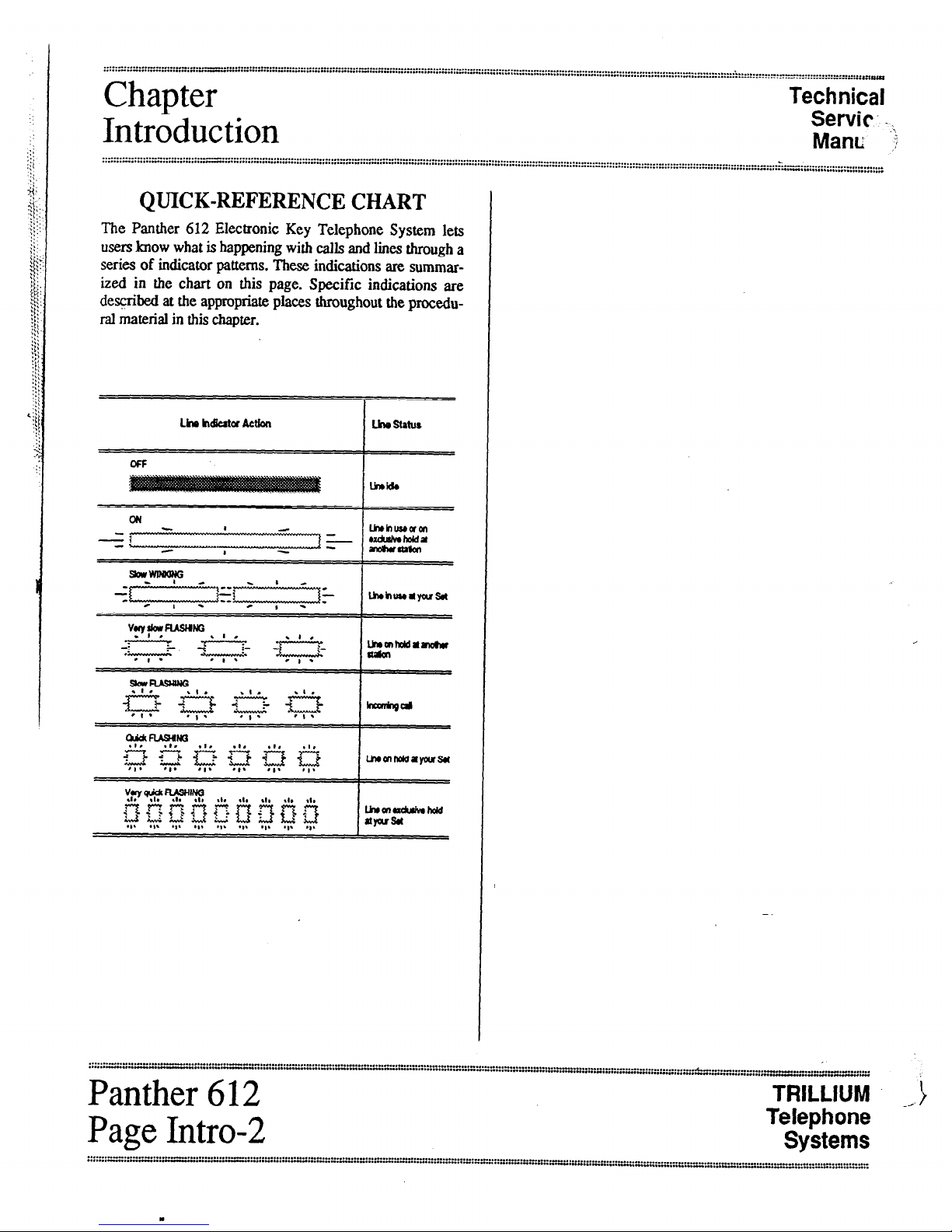
QUICK-REFERENCE CHART
The Panther 612 Electronic Key Telephone System lets
users lmow what is happening with calls and lines through a
series of indicator patterns. These indications are summar-
ized in the chart on this page. Specific indications are
desqibed at the appropriate places throughout the procedu-
ral material in this chapter.
Lim h&atorActbn Lhestatus
lhehuseam
- mdsiv.hokl*
inauapkn
. . . . . . . . . . . . . .
. . . . . . . . ..1.*.......1.- . . . . . . . u
. . . . . . . . . - . . . . . . . . . . . . “m” . . . . . . , . . . . . . . . . . . . . . . . . . . . . . ...” . . . . . . . . . . . I . . . . . . . . . . . . . . . . . ...” . . . . . . . . . . . . . . . . . . . . . . . . . . . . . . . . ..-.......... *...* . . .........................-....-...........--..” ........._.” ........
. . . . ..“..--“.“*...-..“-~-.-..“.* . . . . . . . . . . . . . . . . . ““..‘+” . . . . . . . . “.._.,“...I...” . . . . . . . . I . . . . . ..._.” . . . . . ...” . . . .._._ “.._ _...........,,... ..__..-_
Panther 612
%i LLIUM __)
Page Intro-2
Telephone
Systems
. . . . . . . - . . . . . . . . . ..“I_” . . . . . ..“...rn . . . . . I . . . . . . . .
. . . . . . -“..I . . . . . ..-........-................-.................................................................................. ” . . . . . . .._.....” . . . ..-...................” . . . . . . .._...........................-..............--............. ” . . . . . . . . . . . . .
. . . . . . I . . . . . -“..- . . . . . -.- . . . . . I . . . . . . . . . . . . . _.“I . . . . . . . I .I....... _ .-.........-.. “.“__ -.,._. *...*-._” . . .._..._. “..” __....... “.” . . . . . . . “.“..
.
::::::::::::::::::::::::::::::::::::::::::::::i:::............,........,................._.........................................................................................................................................I...........................................
......*...........-.................-.....................................*................................................................................................................................................,
Technical
Service
FCC
Manual
i Requirements
RADIO AND TELEVISION
INTERFERENCE
WARNING
The Panther 612 Electronic Key Telephone
System generates and usesradio-frequency en-
ergy and - if not installed and used in strict
accordance with these instructions - may
cause interference to radio and television
reception.
The Panther 612 Electronic Key Telephone System hasbeen
certified to comply with the limits for a Class B computing
device, pursuant to Subpart J of Part 15 of the Federal
Communications Commission (FCC) Rules which are de-
signed to provide reasonable protection from radio and
television interference in a residential installation. However
there is no guarantee that interference will not occur in a
particular installation.
If interference is encountered, test to determine if the unit is
at fault by unplugging the Key Service Unit (KSU) from the
( wall outlet
If unplugging-the KSU removes the interference, ay the fol-
lowing corrective measures, singly or in combination, until
the interference is eliminated:
l
Change the location or position of the indoor re-
ceiving antenna of the radio or television.
. Relocate the Panther 612 Set or KSU in relation to
the radio and television receivers experiencing
interference.
. Plug the KSU into an outlet that does not also serve
radio or television sets.
If further help is needed, consult your TRILLIUM dealer or
an experienced radio/television technician - or refer to the
FCC’s booklet, “How to Identify and Resolve Radio-TV
Interference Problems.” It is available from the US
Government Priutiug Office, Washington, DC 20402 (stock
number OO4-000-003454).
HEARING AID COMPATIBILITY
The Panther 612 Set is compatible for those requiring a
hearing aid as defined in section 68.316, Part 68 of FCC
Rules.
/’
\
TRILLIUM
Telephone
‘ Panther-612
Systems
Page A-l

. . . . . . . . . , . . . . . . _- . . . . . . . . . . . . . . . . . . . . . . . . . . . . . . . . . . . . . . . . . . . . . . . . . . - . . . . . . . . . . . . . . . . . . . . :.::::::::::::::::::::::::::::“‘:::::::::::~::~:::::::::.~::::::::::::::::::: ::::: ::::::::: z :::::::::: c:.:::: ::::::; z ::::: :::::::x-:::::.
. . . . . . . . . . . . . * I..... --................................................. - . . . . . . . . . . . . . . . . . . . . --
FCC
Technical
Requirements
Service
Manual
::::::::::::::::::::..1...::::::::::::::::::::::::::::::~:::::::::::::::::::::::::::::::::::::::::::::::::::::::::::::::::::::::::::::::;:::::::::::::::::::::::::::::::::::::::::::::::::::::::::::::::::::::::::::::::::::::::;:::::::::~~::::::::-..---
f .-.
RESPONSIBILITIES
The FCC’s rules permit the Panther 612 Electronic Key
Telephone System to be connected to the telephone network
via a jack or jacks provided by the telephone company
(telco). Thesejacks are not provided for coin or party lines.
UserResponsibilities
Before connecting your Panther 612 Electronic Key
Telephone System to the telephone lines, you must contact
the telephone company and provide them with the following
information:
.
Telephone numbers of the lines to which the
Panther 612 Electronic Key Telephone System is to
be connected (lines 1 through 6)
l
FCC Registration Number (found on the side of the
Key Service Unit or KSU: the number for either the
tone only KSU is EBS78T-71738-KF-T, or, for the
tone/rotary KSU, the number is EBS78T-71738-
=-E)
.
Ringer Equivalence Number (also found on the side
of the KSU: the number for either version of the
Panther KSU is l.lB)*
.
USOC jacks required (usually three 4-conductor.
RJ14 modular jacks)
You also have the responsibility to disconnect a malfunc-
tioning Panther 612 Electronic Key Telephone System from
the telephone lines until the cause of the malfunctioning is
identified and repaired. Otherwise, the telephone company
may temporarily disconnect service.
* The Canadian Department of Communications load num-
ber for the Panther 612 Electronic Key Telephone System is
16-B.
Telco Responsibilities
The telephone company is required to give you adequate no-
tice of any changes it makes in its technical operations cr
procedures that may affect the compatibility or use of your
Panther 612 Electronic Key Telephone System.
=::::::::::::~ :::::::::::::::::::::::::::::::::::::::::::::z*l::::".."".............................."....................I......"".......-..............."..............................".-..........-- -...-.-
.........."................"".."........I...................."."..".."..,"....."......I........."......-............-..""......-. -...-
Panther 612
I
TRILL;UM (
pag
:e
A-2
Telephone
Systems
TechnicalTechnical
ServiceService
ManualManual
System
Components
System
Components
STANDARD COMPONENTS
OneKey ServiceUnit (KSU)
Part Number 90-0166(tone only)
or
Part Number 90-0084(tone/rotary
The ~onelrotary key service unit (KSU) for the Panther 612
Electronic Key Telephone System can be programmed to
operate with either dual-tone, multi-frequency (DTMF) or
rotary (pulse) signaling. The signaling on each Central
< Office (CO) line can be programmed independently. The
tom only KSU operates only with DTMF signaling. Other
than signaling differences, both KSU models look alike and
operate identically.
The KSU has three connectors on its left side (labeled
C01.2, C03.4, and CO%) to attach the six incoming tele-
phone company (telco) CO lines - one connector for each
pair of lines (line 6 must be left vacant if the optional Door
Answer Unit is installed). Also on the left side of the KSU
are connectors labeled DOOR (used for the optional Door
/- Answer Unit), PAGE (used for external paging equipment),
MUSIC (used for an external background and on-hold music
source). POWER FALL (used for the optional Power Fail
Transfer Unit).
Next, the KSU has one recessed light-emitting diode (LED)
indicator (labeled STATUS), four miniature dual in-line
package (DIP) switches (labeled, from top to bottom, 1
PROGRAM [used to return features to their default, factory
preprogrammed conditions], 2 PROGRAM [used to pro-
gram system features], 3 [not used], and 4 BATTERY [used
to save feature programming]), and one recessed pushbutton
(labeled RESET).
Near the bottom left of the KSU is a 50-pin connector, la-
beled STATIONS 10 TO 21/LOUD BELL, that is used to
connect the KSU to the station wiring main distribution
frame (MIX) - and, through the MDF, to alI the system
stations. The last pair is also optionally available for con-
necting an external loud bell or other sounding device
through an external dry contact interface unit.
On the bottom of the KSU is a connector labeled SMDR
(used for the optional SMDR Interface unit).
The KSUs power cord (at the top of the KSU) plugs into a
110 V ac outlet (but only at the appnpriate time; see the
Connection Procedures section). A grounding wire (12
AWG, solid copper) which connects to the top of the KSU
must be attached to a ground clamp, umally on a water pipe.
An input connector (labeled EXTERxti BATTERY) for
an optional 24 V backup battery is aha provided at the top
of the KSU. If ac power is lost, the switchover to backup
battery power is automatic when the qcional backup battery
is connected.
The unit comes with 4 screws for mmting the KSU on a
backboard
Up to Twelve Telephonetits
Part Number 90-0266
(non-handsfree)
&t Number 90-0168
(handsfreewith busylamp field)
Other than the handsfree operation and the busy lamp field,
these two models look alike and operaa: identicatly. For ex-
ample, both have an attractive black marretIni&.
Each Set’sbase has twelve dual-functkm statiort select/speed
call keys (labeled 10 through 21- tix top key is also used
for last number
Redial),sixline
seleukeys (labeled 1,2,3.
4,5, and 6), seven dedicated functim keys (labeled
Hold,
Flash/Cancel, Conference, Intercom, Speed,
Speaker,andMic.on/off) and
a tone d&l keypad
The line
1,2,3,4,5,
and 6 keys, the
Uercom key,
and the
Mic.on/off key
have accompanying szus indicators. And,
only on handsfreebusy lamp field (HFELF) Sets, each sta-
tion select key (10 through
21)
also has an accompanying
status indicator.
Finally, the base has a speaker volume control (a sliding ad-
justment) and a ringer control switch (a ‘J-position switch,
for low, medium, and high volume riqing).
Each Setalso includes a telephone hardset and two modular
cords - a4-conductor, coiled cord fa connecting the hand-
set to the Set, and a 4-conducur modular cord for
connecting the Set to the station wiring jack.
=:=:I” :::::::::::. x:; :::::::: ;:r< ::::::::::::::::::; ::::::::::::: ~‘::.w’“-“:“:~“:::..- . . . . . . . . . . . . . . . . . . . . . . . . . . . . . . . . . . . . . . . . . . . . . . . . . . . . . . . . . . . . . . . . . . . . . . . . . . . . . . ..-...........................
. . . . . ...” . . . . . . . . . . . . “... . . . . . . . . . . . . . . . . . . . . . ...” . . . . . . . . . . . . . . . . . . . . . . . . . . . . . . . . . * . . . . . -..- ._............... I
..” . . . . . . . . . . . . . . --.....“*..* . . . . . . . *..
,-
c
TRILLIUM
Telephone
’ Panther 612
Systems
Page B-l

System
.Technical
Service
Components
Manual
..................................................................- ................d......................................................-
......,......................................
:::::::::::::::::::::“::::::::::::::::::::::::::::::::::::::::::::::;:::::.,.................................................................A ...................”..........................................*.*.......- ............................................. C
OPTIONAL COMPONENTS
OneDoor Answer Unit,
Part Number 90-0058,
With One or Two Door Modules,
Part Number 90-0057
The Door Answer Unit (also known as the Door Answer
Control) is installed next to, andconnects with, the KSU. It
servesas the interface between the system’s stations and the
one or two installed Door Modules (also know as the Door
Answer Boxes) at the desired doors or entryways.
Together, these units enable signaling and conversation be-
tween Set usersand visitors. Like the KSU, these units come
equipped with mounting screws.
A visitor, by pressing the door bell button on a Door
Module, generates a distinctive tone (four groups of 4 short
tones for Door Module 1, four groups of 2 long tones for
Door Module 2) that will sound at all Sets programmed to
ring on line 6 and causes the indicator for line 6 on all Sets
to WlNK. Also, each Set user can generate a calling tone
that will sound at Door Module 1only.
Up to Two Power Fail Transfer Units
Part Number 90-0052
The Power Fail Transfer Unit automatically takes over in the
event of an electrical power failure, allowing for continued
telephone service during the emergency. One Power Fail
Transfer Unit can handle up to 4 incoming lines.
When power fails, the Power Fail Transfer Units transfer in-
comingCOlines(uptoall6ofthem-ortbe5linesinuse,
if the optional Door Answer Unit with Door Modules is in-
stalled) to pre-installed srundard telephone sets (not to
Panther 612 Sets).
Up to Eleven Off PremisesExtensibnl
Data Interface (OPX) units
Part Number 90-0308
‘TheOPX unit converts a 4-wire interface to a 2-wire inter-
face, allowing a single line telephone to be connected to any
spare station jack - except station 10. It also allows 2-wire
devices to be co~ected at a distance greater than the system
2&lO feet limit for Sets. The OPX unit also simulates CO
line charactistics, allowing a modem or an answering ma-
chine to be
co~ected
to the system. Finally, the OPX unit
allows a remote device to be connected to your system at
any distance via a CO line.
When the user lifts the single-line telephone’s handset, an in-
tercom connection is made to the Panther system. Also, by
dialing a special code, the off-premise user can access any
of the Panther system’soutside lines,
One Station MessageDetail Recorder
(SMDR) Interface
Part Number 90-0169only (I .
This unit allows information on system, line, and station
usage to lx captumd and recorded.
:::::::::::::::::::‘~::::::::::::::::::::::::::::::::::::::::::::::::::::::::::::::::::::::::~::~::::~::::::::::::::~::::. -.......-
-.._......_ “::::“:“~n~:“““~:~=-::::~:~:~ . . . . . . . . . . . . . . . . e..... -..... . . . ..-
..“...” . . . . . . . . . . . . . . . . . . ..“...I....... _-
Panther 612 I
TRILLIUM (
Page B-2
Telephone
Systems
. . . . . . ._ . . . . . . . . . . . . . . . . . . . . . . . . . . . . . . . . . . . . . . . . . . . . . . . . . . . . . . . . . . . . . . . . . . . . . . . . . . . . . . . . . . . . . . . . . . . . . . . . . . . . . . . . . . . . . . . . . . . . . . . . . . . . . ..I . . . . . . . . . . . . . . . . . . . . . . . . . . . . . . . . . . . . . . . . . . . . . . . . . . . . . . . . . . . . . . . . . . . . . . . . . . . . . . . . . . . . . . . . . . . . . . . . . . . . . . . . . . . . . . . . . . . . . . . . . . . . . . . . . . . .
. . . . . . . . . . . . . . . . . . . . . . . . . . . . . . . . . . . . . . . . . . . . . . . . . . . . . . . . . . . . . . . . . . . . . . . . . . . . . . . . . . . . . . . . . . . . . . . . * . . . . . . . . . . . . . . . . . . . . . . . . . . . .... * .......... # ....................................................................................................................................
Technical
Service
System
Manual
Components
::::::::::::‘.:::::::::::::::::::::::::::::::::::::::;::::::::’........................................................................................................................
.........................................................................
~
.................
...........................***.**.*..........*.....*...*.....*..............*....................................................................
..................................................................
SetStands/Wall-Mounts
Part Number 90-0087
Each Set may be placed on a desk - or mounted on a wall
using the Set Stand/Wall-Mount Bracket (available in pack-
ages of 10).
The same bracket can also be used to provide a heightened
viewing angle when used with the Set on a desk- or table-
top*
DesignationCards
Part Number 90-0192
(for non-handsfree Sets)
Krt Number 90-0193
(for handsfree/busylamp field Sets)
Designation Cards are used to list the eleven private speed
call numbers and identify the assignment or location of the
twelve system stations.
Although each Set comes equipped with one installed and
one spare Designation Card, you may order additional cards
(in packages of 10) for your system.
Notice that each type of Set uses a different Designation
FacePlates
Part Number 70-0171
(for non-handsfree Sets)
k-t Number 70-0172
(for handsfree/busylamp field Sets)
Face Plates cover and protect the Designation Cards. You
may order spare Face Plates for your system.
Notice that each type of Set usesa d$erent FacePlate.
c.
““‘““‘::::“~~~:~::::::::::::::~~~~:::::::::::::::::~~:~:::::~~:::::::::~~:::::::::::::~~:::::::::::::::::::::::::::.~::::::::::::::::::~::::::::::~::::::::::~:::~::::~::~~~:~~~~~
*::::““..:::::::.z::::“:::::::::z
TRILLIUM I
Telephone
Panther 612
Systems
Page B-3

Technical
Service
Technical
Manual
(. Specifications
..._.......__._._.........................................................................................
,.............................................................................................
........................................
..~............:::::::::::::::::::::::::::::::::::::::~:::::~::::::::::::::::::::::::::::::::::::::::::::::::::::::::::::::::::::::::::::::
CONNECTORS
Equipmenf
CO or PBX lines ..................................................
KSU:
C01.2, C03.4, and C05.6.. ..............................
STATIONS 10 TO 21 (to station wiring MDF) ....
DOOR (to Door Answer Unit jack DA). ..............
POWER FAIL (to first Power Fail Transfer Unit) ..
PAGE (output - 2.00 mV rms into 600 f2).........
MUSIC (music input - 50 mV rms). .................
SMDR (to SMDR Interface unit) ........................
EXTERNAL BATTERY ...................................
Ground ..........................................................
Station wiring MDF:
To station jacks.. .............................................
To dry contact interface (2 A, maximum). ............
Panther 612 Sets (to station jacks) ............................
Door Module (to Door Answer Unit D 1 and D2). .........
Fit Power Fail Transfer Unit (optional):
C01.2 & C03.4 (from incoming lines l-4). .........
TK1.2 & TK3.4 (to KSU jacks C01.2 & C03.4).
CNJ (to KSU jack POWER FAIL). ....................
CNK (to 2nd Power Fail Transfer Unit jack CNJ) ..
Second Power Fail Transfer Unit (optional):
C01.2 (from incoming lines 5 & 6)....................
TK1.2 (to KSU jack C05.6) ..............................
CNJ (to 1st Power Fail Transfer Unit jack CNK) ...
SMDR Interface unir
To KSU connector SMDR.. ..............................
To printer, terminal, or personal computer.. ..........
JackstConnections
Cable Pairs
Modular RJ14C ....................... A total of 6 (one per line)
Modular RJ14C ......................
50-pin RJ21C to 66-block .........
Modular RJ25C .......................
Special connector .....................
Mini-Jack l/&inch, phono) ........
Mini-Jack (l/&inch, phono) .......
Special ...................................
Molex connector ......................
Screw terminal ........................
66-block to modular RJ14C.. .....
66-block to screw terminals.. .....
Modular RJ14C (or RJ25C**) ....
Screw terminals.. .....................
Modular RJ14C.. .....................
Modular RJl4C.. .....................
Special connector.. ...................
Special connector.. ...................
Modular RJ14C.. .....................
Modular RJ14C.. .....................
Special connector.. ...................
special ...................................
DB-25 ....................................
2each
25
3
(See first Power Fail Transfer Unit)
1
&e SMDR Interface)
1’
Single 12 AWG wire
2 each*
1
2 each, cord supplied (or 3**)
1for each module
2each
2t.!ach
1(cable supplied)
(See 2nd Power Fail Transfer Unit)
2each
2each
1(cable supplied)
Special (cable supplied)
RS-232 cable
SMDR INTERFACE UNIT (optional)
Data
code.. ............................................................................................................ ASCII
Data rates (SMDR switch-selectable) ......................................................................... 300.600. or 1200 bits per second
Output device (user supplied) .................................................................................... 8a-character, serial printer
Time before recording starts (programmable) ............................................................... lto6lseconds
Grace period before timer starts (programmable) ..................................................... ltol6seconds
Account Codes (as they appear in SMDR printout) ....................................................... “A”+ 4 user-entered digits
* Length of each station cable should not exceed 2000 feet of 2A AWG; ail station runs are star (home,r@ configurations
** Setsmay alternatively use a 6-conductor modular cord-toRJ25C jack (to gain accessto the Set’sspeaker terminals)
c
TRILLIUM
Telephone
Systems
I
Panther .612
Page C-l
Technical
Specifications
Technical
Service
Manual -
......................................................................................................................................................................................._...................._...............-_.......
....................................................................................................................................................................................“_”...............^._..............._......
::::::~:::::::::::::::“::::::::::
c
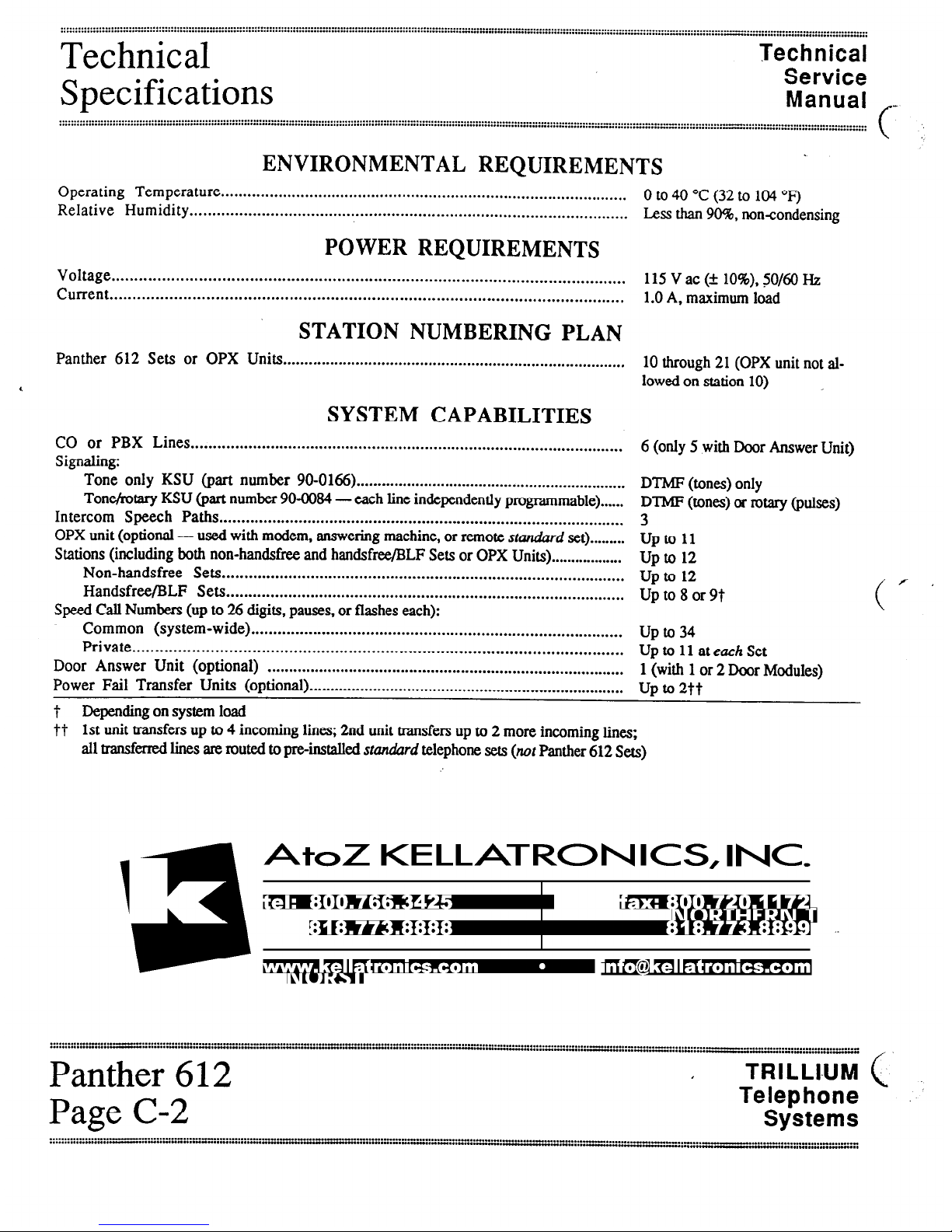
ENVIRONMENTAL REQUIREMENTS
Operating Temperature ............................................................................................ 0 to 4I) “C
(32
to104
Relative Humidity
“F)
.................................................................................................. Less than 90%. noncondensing
POWER REQUIREMENTS
Voltage ................................................................................................................
Current 115 V ac (* 10%). 50/60 Hz
................................................................................................................ 1.0 A, maximum load
STATION NUMBERING PLAN
Panther 612 Sets or OPX Units ................................................................................ 10 through 21 (OPX unit not al-
lowed on station 10) _
SYSTEM CAPABILITIES
CO or PBX Lines ..................................................................................................
Signaling:
Tone only KSU (part number 90.0166) ................................................................
Tor&otary KSU (part number 90.0084 - each line independently programmable) ......
Intercom Speech Paths ............................................................................................
OPX unit (optional - used with modem, answering machine, or remote standard set).........
Stations (including both non-handsfree and handsfree/BLF Sets or OPX Units). .................
Non-handsfree Sets...........................................................................................
Handsfree/BLF Sets..........................................................................................
Speed Call Numbers (up to 26 digits, pauses. or flashes each):
Common (system-wide) ....................................................................................
Private ...........................................................................................................
Door Answer Unit (optional) ...................................................................................
Power Fail Transfer Units (optional) ..........................................................................
6 (only 5 with Door Answer Unit)
DTMF (tones) only
DTMF (tones) or rotary (pulses)
3
upto 11
upto 12
upto 12
UptogorBt
Upto
UptollateuchSet
1 (with 1 or 2 Door Modules)
up to
2tt
t Depending on system load
tt 1st unit transfers up to 4 incoming lines; 2nd unit transfers up to 2 more incoming lines;
all transferred lines are routed to p&nstalled
stun&rd
telephone sets
(not
Panther 612 Sets)
AtoZ KELLATRONICS, INC
/
(
. . . . . . . . . . . . . . . . . .
. . . . . a... . . . . . . . . . . . -
. . -“.‘:::::::“:::::::““::“::“:::“::”:::” :::::::: ~::“::“:::” -........” ._....-” . . . . . . . . . ..___
_II” . . . . . . ..“- . . ...” . . . . . “....““‘::“:“::::.~:::~~~
Panther
612
I
TRILLI-UM (
Page
C-2
Telephone
Systems
Technical
Service
Manual
/
:::::::::::::::::::::::::::::::::::::::::::::::::::::::::::::::::::::::::::::::~:::::::::::::::::::::::::::::::::::::::::::::::::::::~
STEP
1
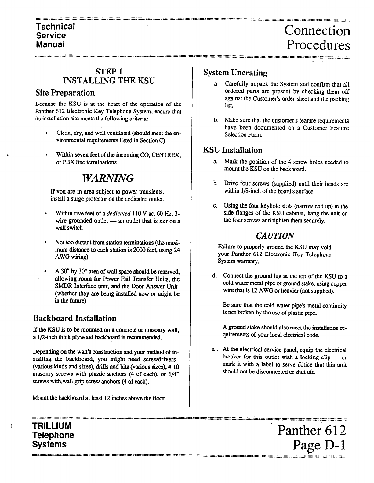
INSTALLINGTHEKSU
SitePreparation
Because the KSU is at the heart of the operation of the
Panther 612 Electronic Key Telephone System, ensure that
its installation site meets the following criteria:
. Clean, dry, and well ventilated (should meet the en-
vironmental requirements listed in Section C)
. Within seven feet of the incoming CO, CENTREX,
or PBX line terminations
WMNING
If you are in area subject to power transients,
install a surge protector on the dedicated outlet
. Within five feeCof a dedicated 110 V ac, 60 Hz, 3-
wire grounded outlet -
an outlet that is not
on a
wall switch
. Not too distant from station terminations (the maxi-
mum distance to each station is 2000 feet, using 24
AWG wiring)
. A 30” by 30” area of walI space should be reserved,
allowing room for Power Fail Transfer Units, the
SMDR Interface unit, and the Door Answer Unit
(whether they are being installed now or might be
in the future)
Backboard Installation
If the KSU is to be mounted on a concrete or masonry wall,
a l/2-inch thick plywood backboard is recommended.
Depending on the wall’s construction and your method of in-
stalling the backboard, you might need screwdrivers
(various kinds and sizes), drills and bits (various sizes),# 10
masonry screws with plastic anchors (4 of each), or l/4”
screws wjkwall grip screw anchors (4 of each).
Mount the backboard at least 12 inches above the floor.
Connection
Procedures
. . . . . . . . . . . . . . . . . . . . . . . . . . . . . . . . . . . . . . . . . . . .
I... . . . . . . . . * . . . . . . . * . . . . . . I . . . . . . . . . . . . . . . ::::::::::::::::::::::::I::::::::::::::::::::::::::::::::::::::::::::::~::::::::::::::::
SystemUncrating
a Carefully unpack the System and confirm that all
ordered parts are present by checking them off
against the Customer’s order sheet and the packing
list
h Make sure that the customer’s feature requirements
have been documented on a Customer Feature
Selection Form.
KSU Installation
a. Mark the position of the 4 screw holes needed to
mount the KSU on the backboard.
b. Drive four screws (supplied) until their heads are
within l/8-inch of the lxxrd‘s surface.
c. Using the four keyhole slots (narrow end up) in the
side flanges of the KSU cabinet, hang the unit on
the four screws and tighten them securely.
CAUTION
Failure to properly ground the KSU may void
your Panther .612 Electronic Key Telephone
System warranty.
d Connect the ground lug at the top of the KSU to a
cold water metal pipe or ground stake, using copper
wire that is 12 AWG or heavier (not supplied).
Be sure that the cold water pipe’s metal continuity
is not broken by the use of plastic pipe.
A ground stake should also meet the installation re-
quirements of your local electrical code.
e . At the electrical service panel, equip the electrical
breaker for this outlet with a locking clip - or
mark it with a label to serve notice that this unit
should not be disconnected or shut off.
l
TRILLIUM I
Telephone
Panther 612
Systems
Page D-l
,......”...................................
....-.............I............e.......................................................................-I.....................
..-.........................................................................................----..............-.
__.......”.......
...*..........................”..........“.I......”.....-.................................L.._..“..”.............................._
..............................”
._._................_-............
_,

Connection
Procedures Technical
Service
Manual
..........................................I...........I....................................................................................................................,......................................
...............................................................-.................................................................................................................................................:::::::::::::::::::::~:::::::::
“‘::::::::::::::::::::::::::
f
STEP2
CONNECTING
INCOMINGTELEPHONELINES
WARNING
Do not plug in the KSU’s power cord until in-
structed to do so in Step.4.
NOTES
1. If the incoming telephone lines are not yet
installed, ask the telco that they be terminated,
each 2 lines in a single 4-conductor RJ14 jack.
2. If optional Power Fail Transfer Units are to
be installed, follow the instructions in Step 12
to connect the incoming lines.
3. If the optional Door Answer Unit is to be in-
stalled,line6
must be left vacant.
If the incoming lines are terminated in RJ14 jacks - with
each 2 lines terminated in a single RJ14 jack - simply in-
stall one 4conductor, modular line cord between the single
RJ14 jack at which incoming lines 1 and 2 both terminate
and the jack labeled CO 1.2 on the left side of the KSU.
Similarly, install a 4conductor, modular line cord between
the single RJ14 jack at which incoming lines 3 and 4 both
terminate and the jack labeled C03.4 on the left side of the
KSU.
Finally, install a 4-conductor. modular line cord between the
single RJ14 jack at which incoming lines 5 and 6 both termi-
nate and the jack labeled CO56 on the left side of the KSU.
STEP3 .-
INSTALLINGSTATIONWIRING
WARNING
To prevent damage to the KSU while wiring,
make sure that the KSU’s power cord is not
plugged in. Do not apply power to the KSU
until instructed to do so in Step4.
NOTES
1. Becausemuch of the feature programming is
performed from station 10, choose a conven-
ient or strategic location for station 10.
2. If an external amplifier/speaker is to be used
at any of the station locations, mount a 6-
conductor RJ25 jack at the station location in-
stead of a 4conductor RJ14 jack SeeStep 13.
3. Refer to the Typical System Layout
Diagram (on page E-l) and the Station
Wiring
Table (that starts on the facing page) for wiring
details f/
a
h
C.
d.
e
\
Decide on the location and station number (from 10
up through 21) for each Set.
Mount a 4-conductor RJ14 jack within 6 feet of the
desired Set location at each station.
On the backboard, mount a 66-block with a female
50-pin connector.
Installa25-pair
cable - with male 50-pin connec-
tors at both ends - between the 66block’s 50-pin
connector and the KSU SO-pin connector labeled
STATIONS 10 TO 21. Secure the KSU end of the
cable with the screw and plastic tie-wrap provided
with the unit.
For each station, install a length (not to exceed
2000 feet) of 4-conductor, 24 AWG cable from the
66-block terminals to the station wiring jack.
. . . . . . ..-.... I . . . . . . . . . . . . . . ..-.. . . . . . . . . . . . . . . . . . . . . . . . . . . . . . . . . . . . . . . . . . . . . . . . . . . . . . . . . . . . . . . . . . . . .
. . . . . . . . . . - . . . . . I............. . . . . . . . . . . . . . . . . . . . . . . . . . _” . . . . . . . . . . . . . . . . . . . . . . . . . . . . . . . . ...” . . . . . . . . . . . . . . ...” . . . . . . . . . .
. . . . . . . . . . . . . . . . . ..-..................... ” .._...............-.....................-.................... ” ..........
. . . . . . . . ...” .--................_._ . . . . . . . . . . .._._.........-.... ““.” .......... - . . . . . . “....”
-.-.... :.
Panther 612 I TRILLIUM(‘f ..
Page D-2 Telephone
Systems

Technical
Service
Manual
Connection
Procedures
.._,..........,........,...........................................,..........,..........................................................._.........
...,..........,.
...........................................................................................................................-........
;::::::--r::::::~::::~::::::::::::::::::::::::::::::::::::::::::::::::::::::::::::::
....................,
...................
Station
Number
10
11
12
1s :.
14
15
Circuit CConductor 66-Block SO-Pin 25 Pair
Function Station Jack? Termhal Connector Cable*
voice (tip) green GN) 1 26 white/blue
voice (ring) red W) 2 1 blue/white
data WP) black (BK) 3 27 white/orange
data (ha yellow (YL) 4 2 orange/white
voice (tip) green WO 5 28 white/green
voice (ring) red (RD) 6 3 green/white
data (GP) black (BK) 7 29 white/brown
data (ring) yellow (YL) 8 4 brown/white
voice (tip) gTeen(W 9 30. white/slate
voice (ring) red WI 10 5 slate/white
data WP) black (BK) 11 31 red/blue
data b-ha yellow (YL) 12 6 blue/red
voice (tip) green (0 13 32 redorange
voice (ring) red (RD) 14 7 orange&d
data @PI black (BK) 15 33 red/green
data(ring) ’ yellow (YL) 16 8 green/red
voice (tip) green (0 17 34 red/brown
voice (ring) d(RD) 18 9 brown/red
data (GP) black (BK) 19 35
l-d/Slate
data w%) yellow (YL) 20 10 slate/red
voice (tip) green (GN) 21 36 black/blue
voice (ring) .=d(RD) 22 11 blue/black
data (GP) black (SK) 23 37 black/orange
data ww) yellow (YL) 2A 12 orange/black
f Usemathing color codesfor the4-amdnctor smion wiring cables.
* The first colorlistedisthepredominant
Color the second c&r listed is tbt tracex
or seipe color.
Station Wiring Table (Sheet1 of 2) -
,_-
i
TRILLIUM
Telephone
Systems
’ Panther-612
Page D-3

Connection
Procedures
Technical
Service
Manual _
Station
Number
16
17
18
19
20
21
Circuit 4-Conductor 66-Block SO-Pin 25 Pair
Function Station Jackt Terminal Connector Cable*
voice (tip) green (W 25 38 black/green
voice (ring) red (RD> 26 13 green/black
data (tip) black (BK) 27 39 black/brown
data w%) yellow (YL) 28 14 brown/black
voick (tip) green (W 29 40 . black/slate
voice (ring) red CW 30 15 slate/black
data (tip) black (BK) 31 41 yellow/blue
data (fig) yellow (YL) 32 16 blue/yellow
voice (tip) green WI 33 42 yellow/orange
voice (ring) red WI 34 17 orange/yellow
data (tip) black (BK) 35 43 yellow/green
data @WI yellow (YL) 36 18 green/yellow
voice (tip) green GN) 37 44 yellow/brown
”
voice (ring) red WI 38 19 brown/yellow
data (tip) black (BK) 39 45 yellow/slate
data 0-w yellow (YL) 40 20 slate/yellow
voice (tip) green GW 41 46 violet/blue
voice (ring) red (RD) 42 21 blue/violet
data (tip) bhd 0 43 47 violet/orange
data (e%) yellow (YL) 44 22 orange/violet
voice (tip) green GN) 45 48 violet/green
voice (ring) red 0) 46 23 greenhiolet
data (tip) black (BK) 47 49 violet/brown
data w%) yellow (YL) 48 ’ 24 brown/violet
t Usematchingcolor codesfor the4umductor stationwiring cables.
* The first color listedisthepredominant color; thesecondcolorlistedisthetracer
or stripe color.
Station Wiring Table (Sheet2 of 2)
Panther612 I
TRILLIUM 4”
Telephone
Systems
PageD-4

Technical
Service
Manual
Connection
Procedures
:::;::::::::::::::::::::::::::::::::::::::::::::::::::::::::::::::::::::::::::::::..........................................................................................................................................................-..-”............................,
......... .........*.............................*.....................................................................................-....................- .........-.................,
STEP 4
CONDUCTING THE INITIAL
SYSTEM AND STATION TESTS
NOTES
1. If the indications described below do not
occur, refer to the Troubleshooting section.
2.If the SMDR Interface unit is to be installed,
it should be installed
prior to
conducting these
tests. seestep 11. -
a Connect the KSU power cord to the surge protector
previously installed at the 110 V ac power outlet:
the recessed STATUS indicator goes ON (with a
slight flicker) indicating that the KSU is operative.
b. Set KSU switch 4 BATTERY to ON (if necessary,
use a paper clip or other pointed object such as a
pen or pencil to set the KSU miniature DIP
switches).
c Set KSU switch 1PROCRAM to ON.
d Push the recessed RESET pushbutton once.
e SetKSU switch 1 PROGRAM to OFF.
f. Push the recessed RESET pushbutton again: the
system is now set the factory preprogrammed con-
ditions (for details on what those conditions are, see
the Feature Programming section).
g. At station 10, plug in the 4-conductor modular cord
supplied with the Set between the Set and the sta-
tion wiring jack
h Press the Set’s
Intercom
key: the Set’s speaker
emits a continuous tone and
theIntercom
indicator
goesON.
i Lift the handset and press the line 2 key: dial tone
is heard; the
Intercom
indicator goes OFF; if
yours is a BLF Set, yout station indicator goes ON,
and the line 2 indicator WINKS slowly.
j. Hang up the handset: dial tone is removed; and all
indicators go OFF.
k Repeat steps i and j for lines 1.3.4, and 5 - and
line 6 as well, if not used for the Door Answer
Unit
L Repeat steps g through k for the remaining stations.
Unless you have optional items to install (the Door Answer
Unit, the OPX unit, the SMDR Interface unit, the Power Fail
Transfer Unit, external paging equipment, a dry contact in-
terface, or a music source), your Panther 612 Electronic Key
Telephone System is now ready for programming or
operation.
STEP 5
CONNECTING
THE BACKUP BATTERY
The KSU has a white plastic Molex connector at its top for
connecting an external backup battery. The backup battery
used (such as the TRI 24/2.5B from Alpha Technologies)
should provide 24 V dc at 2 Amps for an extended period of
time.
a Connect the positive (+) terminal of the battery
(usually the red lead) to the left side of the KSU
connector.
b Connect the negative (-) terminal of the battery
(usually the black lead) to the right sideof the KSU
connector.
Once connected, switchover to the backup battery occurs au-
tomatically when power fails.
:
I
TRILLIUM
Telephone
Panther 612
Systems
Page D-5

Connection
Procedures
Technical
Service
Manual f’.
. . . . . . . . . . . . . . . . . . . . . . . . . . . . . . . . . . . ...” . . . . . . . . .
I................................................ ::::::::::::::::::::::::::::::::::::::=”::::::::c::::::::::“”:::::::::::::::::::::::::::::::::::::::::::::~ ::::::::::::::::::::: z ::::::::::::::::::::::::::::::::::::::::::::::::::::::::::::::::::::::::::: (,
STEP 6
CONNECTING
DOOR ANSWER UNIT
AND DOOR MODULES
NOTE
If you have chosen to install the Door Answer
Unit with its one or two Door Modules, line 6
must be left vacant
Door Answer Unit Installation
G
a Mount the Door Answer Unit on thi: backboard
along with the KSU, using the four screws supplied
with the equipment.
b C%‘mect a 6-conductor modular cord (not supplied)
to the connector labeled DOOR on the KSU and the
connector labeled DA on the Door Answer Unit.
.Door Module Installation
a
h
C.
d
e
f.
g.
Remove the screw securing the Door Modules’
front cover, and separate the front from the back.
Mount the backs of the Door Modules at the de-
sired entryway locations, using the two mounting
screws furnished with each Door Module.
RM a length (not to exceed 2000 feet) of 2-
conductor, 24 AWG wire from the Door Answer
Unit to each Door Module.
Feed the wire through the hole in the base of the
back of the Door Module.
Strip the cable end and secure it to the screw termi-
nals found on the backside of the Door Module’s
fhnt assembly.
Replace the Door Module’s cover and tighten the
screw to secure the front to the back.
At the Door Answering Unit, strip the cable ends
and secure the cable from Door Module 1 to the
screw terminals labeled Dl and the cable from
Door Module 2 to the screw terminals labeled D2.
. . . . . . . . . . . . . . . . . . . . . - . . . . . - . . . . . . . . . . . . . ~ . . . . . . ...” . . . . -
. . . . . . . . . . . . I . . . . . . -““- . . . . . . . . . . . -..“““...“- .y’:..z- . . . ...” . . . . . . . . . . . . . . . . . . . . . . . . . ...”
m . . . . . . . . . ...” . . . . “I..“.......- “:::“‘“‘“.““::::::::““‘:::::“‘::::”::: ..:‘-...“::..~~““:““‘:: __
Panther 612 I
TRILLIUM 6
Page D-6
Telephone ..
Systems
Other manuals for Panther 612
1
Table of contents
Other Trillium Telephone manuals

Trillium
Trillium Talk To 308 User guide

Trillium
Trillium Talk To 616 User manual

Trillium
Trillium Talk To 308 User manual

Trillium
Trillium Panther 306 Operating manual

Trillium
Trillium Panther II 820 User guide

Trillium
Trillium Talk To 616 Configuration guide

Trillium
Trillium Talk To 1032 User guide

Trillium
Trillium Panther II User manual

Trillium
Trillium Talk To 616 User manual

Trillium
Trillium Talk To 1032 User manual


