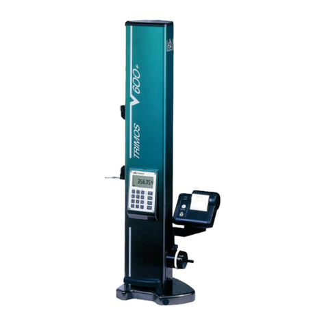
TRIMOS V3 User manual

USER’S MANUAL
V3 / V4 / V5 / V6 / V8
750 50 0045 03


TRIMOS SA
Av. de Longemalle 5
CH - 1020 Renens
T. + 41 21 633 01 01
F. + 41 21 633 01 02
www.trimos.com
1
Dear customer, congratulations for choosing a TRIMOS measuring instrument. For more
than 40 years, our products have built up an excellent reputation in terms of quality, accuracy
and longevity. For full satisfaction with the present product, we recommend to read this
user’s manual carefully.
750 50 0045 03 Version 1.6/2019-01
Valid for following firmware versions:
Module 1.29
Mainboard 2.37
Sensor 3.30
TRIMOS ® - All modification rights reserved

User's Manual
750 50 0045 03 2
CONTENTS
1. Safety regulations............................................................................................................... 4
1.1 Important Information ................................................................................................ 4
1.2 Security Symbols........................................................................................................ 4
1.3 General Warnings....................................................................................................... 4
2. Instrument Description ...................................................................................................... 5
2.1 Instrument................................................................................................................... 6
2.2 Interfaces/Connectors............................................................................................... 6
2.3 Display........................................................................................................................ 6
3. Setting up ............................................................................................................................ 7
3.1 Packing List ................................................................................................................ 7
3.2 Setting-up ................................................................................................................... 8
4. Getting Started.................................................................................................................. 10
4.1 Displacement Modes : Manual/Motorized.............................................................. 10
4.2 Setting into Operation ............................................................................................. 11
5. Main Functions.................................................................................................................. 13
5.1 Selection of Height and Diameter / Centerline Measurements .............................. 13
5.2 Height Measurements .............................................................................................. 13
5.3 Diameter and Centerline Measurements................................................................. 14
5.4 References................................................................................................................ 16
5.5 Selection of the Resolution ...................................................................................... 16
5.6 Setting / Memorizing of the Probe Constant .......................................................... 17
5.7 Selection of the Measuring Unit .............................................................................. 17
5.8 Measuring in Min / Max / Delta Mode .................................................................... 17
5.9 Average Between 2 Last Measurements ................................................................. 19
5.10 Difference Between 2 Last Measurements.............................................................. 20
5.11 Zero Setting of the Display ...................................................................................... 20
6. Secondary Functions........................................................................................................ 21
6.1 Perpendicularity Measurement ................................................................................ 21
6.2 Measurement History (Buffer).................................................................................. 23
6.3 Distance and Centerline Measurement ................................................................... 25
6.4 Inversion of the Measuring Direction....................................................................... 26
6.5 Probe Holder Change .............................................................................................. 27
6.6 Manual Recording of the Probe Constant............................................................... 27
6.7 Display Modes ......................................................................................................... 28
6.8 Shrinking Factor ....................................................................................................... 28
6.9 Temperature Compensation .................................................................................... 29

V3 / V4 / V5 / V6 / V8
750 50 0045 03 3
7. Data Transfer and Print-out ............................................................................................. 30
7.1 USB Connection....................................................................................................... 30
7.2 RS232 Connection ................................................................................................... 31
8. Remote control of the instrument.................................................................................... 32
8.1 Command attributes ................................................................................................ 32
8.2 List of commands..................................................................................................... 33
9. Configuration..................................................................................................................... 35
10. Application and Adjustments.......................................................................................... 40
10.1 Probing ..................................................................................................................... 40
10.2 Air Cushion (V4 ÷ V8) ............................................................................................... 40
10.3 Adjustment of Floating Probe Suspension Balancing ............................................. 41
10.4 Other motorised movement methods (V5 & V6) ..................................................... 41
10.5 Replacement of Battery Block .................................................................................. 42
10.6 Recycling of Electronic Components ...................................................................... 42
10.7 Resetting of the Instrument...................................................................................... 42
10.8 Cleaning ................................................................................................................... 42
11. After Sales Service ........................................................................................................... 43
11.1 Complaints / Repairs................................................................................................ 43
11.2 Agents ...................................................................................................................... 43
12. Dimensions........................................................................................................................ 44
12.1 V3, V4, V5, V6 ........................................................................................................... 44
12.2 V8.............................................................................................................................. 45
13. Technical Specifications.................................................................................................. 46
14. Declaration of Conformity................................................................................................ 49
User's Manual
750 50 0045 03 4
1. SAFETY REGULATIONS
1.1 Important Information
In order to prevent any damages due to wrong manipulation, please carefully read the
following instructions. TRIMOS will not accept any responsibility in case of damages caused
by inadequate use not in line with the present manual.
1.2 Security Symbols
The following security symbols are used in this manual:
General warning, utilisation advice
Risk of electric shock
Electrostatic protection
1.3 General Warnings
Protection against electrostatic interferences:
Static electricity can damage the electronic components of the instrument. In
order to prevent this type of damages, avoid any contact with the connector pins.
In order to prevent any changes of the instrument performance or any accident,
the instrument should never be dismantled.
If, for any reason, the electronic unit has to be opened, only authorized personnel
are allowed to do so.
Do not expose the instrument, its components and accessories to rain or any
projection of fluids. Avoid penetration of foreign substances into the connectors
and the instrument openings.
Do not cover or wrap the display unit during use. The unit must be kept well
ventilated to avoid any overheating.
In case of problems with the instrument or any of its parts (no display,
overheating, abnormal smell...), immediately switch off the instrument and
disconnect the power supply. Please contact your local TRIMOS agent.
This is a high accuracy instrument. Particular care should be taken during its entire
operational lifetime. Pay special attention to the following specific points :
- Use the instrument on a stable, smooth and clean surface plate.
- Avoid any shock to prevent the instrument from losing its characteristics.
- Use the instrument in a vibration free area.
- Avoid exposure to direct sunlight and excessive humidity.
- Avoid proximity of heating or air conditioning systems.
- Respect the advised environmental conditions.

V3 / V4 / V5 / V6 / V8
750 50 0045 03 5
2. INSTRUMENT DESCRIPTION
8
10
7
5
4
3
2
1
6
2.1
2.3
38
32
33
34
35
36
37
39
31
2.2
9
11
21
12
22
23
24

User's Manual
750 50 0045 03 6
2.1 Instrument
1. Upper probe holder (V4 ÷ V6)
2. Screw for the adjustment of the floating probe suspension
3. Handle for carriage displacement
4. Transport safety screw for locking of probe suspension (chromium plated)
5. Lower probe holder
6. Insert holder (V3 ÷ V6)
7. Measuring insert
8. Operating handle for the displacement of the instrument
9. Button for activation of air cushion and programmable functions keys (V4 ÷ V6)
10. Base with air cushion system for instrument displacement (V4 ÷ V6)
11. Handwheel for carriage displacement / Activation of manual/motorised movement
(V5 ÷ V6)
12. Buttons for motorised displacement (V5 & V6)
2.2 Interfaces/Connectors
21. Mini USB connector (on top of display unit)
22. Connector for electronic perpendicularity probe (V6 & V8)
23. Connector for RS232 communication (on lower right side of height gauge)
24. AC adaptor connection (on lower right side of height gauge)
2.3 Display
31. Status symbols (battery level, units, active functions, etc.)
32. Upper display line
33. Lower display line
34. Visual signal of function activation
35. On/Off key (power ON / OFF)
36. Print-out of data
37. Function key: Selection of height and diameter - centerline measurements / Validation
key
38. Function buttons and numeric keypad.
39. Zero setting of the display

V3 / V4 / V5 / V6 / V8
750 50 0045 03 7
3. SETTING UP
3.1 Packing List
The standard packing of the instrument includes the following elements:
1. Instrument with display unit and measuring
insert holder
2. Measuring insert
3. Setting gauge
4. Charging unit
5. Protection cover (V5 & V6)
6. User’s manual (V4 ÷ V6) / Quick guide (V3)
7. Calibration certificate
While unpacking, carry the instrument by lifting if by its displacement handle (8)
and body. In NO case should the instrument be carried by the handle for
carriage displacement (3). Keep the original packaging for future transportation.
If the instrument has been stored at a temperature below 5°C, wait a few hours
before unpacking to prevent the instrument parts from condensation.
Condensation can affect sensitive parts of the instrument.

User's Manual
750 50 0045 03 8
3.2 Setting-up
After unpacking, prepare the instrument as follows:
1. Clean the pads positioned underneath the
base using a clean cloth, slightly dampened
with alcohol.
2. Position the instrument with care on a clean
measuring plate.
3. Mount the display unit on its support using
the 2 screws..
4. Connect the HDMI cable between the
instrument and the display unit.
The straight connector shall be connected to the display unit and the right-angle
connector to the instrument.
Static electricity can damage the electronic components of the instrument. In
order to prevent this type of damages, avoid any contact with the connector
pins.

V3 / V4 / V5 / V6 / V8
750 50 0045 03 9
5. Slide the measuring insert into the holder and lock
it, using the knob. Take care to position the
eccentric probes correctly.
6. Release the transport safety screw.
7. Check / adjust the floating probe suspension
balancing (§ 10.3).
8. If the instrument does not switch on or in
case of low battery level, proceed to a full
loading of the batteries (plug in the charging
unit to the instrument). Empty batteries are
fully loaded in about 3 hours.
Only use the charging unit supplied with the instrument to load the batteries.
It is not necessary to wait until the battery pack is fully charged. The instrument
becomes operational immediately after having connected the charging unit.
It is not dangerous to leave the charging unit connected. Permanently plugged-in
instruments automatically switch to trickle charge mode.
The batteries are of Lithium-ion type. An excessive room temperature can affect
the battery capacity and therefore the instrument autonomy. It is not
recommended to load the battery in case of room temperature superior to 40C°.
Incorrect loading of the battery can result in a decrease of capacity, overheating,
or even an explosion and cause important damages.
The battery can be loaded and unloaded 300 times before a significant reduction
of their capacity. The number of loading cycles and the autonomy can vary
according to use and operating conditions.
V3
V4
V5
V6
V8
V3, V4, V5, V6
V8

User's Manual
750 50 0045 03 10
4. GETTING STARTED
4.1 Displacement Modes : Manual/Motorized
4.1.1 Manual Displacement Mode
V3, V4 & V8
The manual displacement of the carriage is carried out with
the help of the handle. This is the only possible
displacement mode for V3 & V4. The V8 has a fine
adjustment.
V5 & V6
Push the handle inwards in order to pass into manual
mode. In manual mode, V5 & V6 are used in the same way
as V3 & V4.
4.1.2 Motorized Displacement Mode (V5 & V6)
Pull the handle outwards to work in motorized mode. In this
mode, the rotating handle can be tucked inside for
ergonomic reasons.
The motorized displacement is carried out with the 2
buttons situated behind the handle. For other motorized
displacement methods, see § 10.4.
Rapid Displacement
A prolonged pression on one of the buttons causes a rapid
movement in the chosen direction. The carriage will
continue its displacement as long as the pressure is
maintained.
Slow Displacement (Probing)
A short pressure causes a continuous displacement in
probing speed, i.e. speed used for measuring. As soon as
the probe gets in touch with a surface, a measurement is
made.
Release of Probe
When the probe is in contact with the part (after probing),
a short pressure on the button for the opposite direction
allows to release the probe (ca. 0.5 mm).
Movement Stop
While displacing in low speed mode, a short pressure on
the button for the same direction as that of the
displacement will stop the movement.
Activation of
motorised mo
de
(V5 & V6)
Button for upward
displacement
Button for downward
displacement
Activation of
manual
mode
(V5 & V6)

V3 / V4 / V5 / V6 / V8
750 50 0045 03 11
4.2 Setting into Operation
1. Switch on the instrument by pressing button
On/Off during 2 seconds. All segments of the
display will light up.
Switch off the instrument by pressing the same
button until the instrument turns off.
> 2 s
2. The display will ask for the reference position.
Move the measuring carriage slowly across the
mark indicating the reference position with the
help of the handle for carriage displacement (the
acquisition of reference is carried out by
displacing the carriage upwards). An acoustic
signal will confirm that the reference has been
detected and the display starts counting. If the
display does not start counting, repeat the
sequence.
Note :
This procedure is automatically carried out in
motorized mode (V5 & V6). The probe will
position itself at the same level as the reference
gauge (see below).
3. The instrument is now asking for the probe
constant. This function compensates the
dimension and the deflexion of the measuring
insert when probing downwards and upwards
(reversed surfaces, diameters). The last stored
probe constant value will be displayed.
Note 1 :
This procedure may be interrupted by pressing on
the probe constant key or on the
Validation key
.
The latest probe constant value measured is then
recorded.
Note 2 :
The start mode can differ, according to the
instrument configuration (§ 9).
or

User's Manual
750 50 0045 03 12
4. Use the setting gauge supplied with the
instrument to carry out this operation.
Note:
A different setting gauge may be used. In this
case, its dimension must be configured in the set-
up menu (§ 9).
5. Move the measuring insert downwards (use the
handwheel for the displacement of the measuring
carriage) until it touches the surface and an
acoustic signal confirms the measurement
(=probing).
6. Without moving any part (instrument and gauge),
move the measuring insert towards the top and
perform the same sequence on the upper surface
of the setting gauge.
7. Repeat the sequences 5 and 6 one more time.
This allows establishing the probe constant more
precisely.
2x
8. The screen will display the setting gauge value
during the latest probing, as well as that of the
new probe constant. The instrument is then ready
to be used.
In motorized mode (V5 & V6) this procedure can be
automatically carried out by pressing the key opposite
The probe constant needs to be checked and stored again after each measuring
insert change, after change of its position in the holder, after each adjustment of
the measuring force or adjustment of the floating probe suspension.

V3 / V4 / V5 / V6 / V8
750 50 0045 03 13
5. MAIN FUNCTIONS
5.1 Selection of Height and Diameter / Centerline Measurements
To select the functions of height measurements or
diameter/centreline distances, press the
Function key
.
The corresponding symbol will be displayed.
Height
diameter / centerline
5.2 Height Measurements
H1 = Height measurement downwards ( )
H2 = Height measurement upwards ( )
H12 = Chain dimensions
H1
H2
H12

User's Manual
750 50 0045 03 14
1. Select height measurement mode.
2. Set the display at zero or at a preset value with
the measuring insert probing a reference
surface (see § 5.11 and § 5.4.2).
or
3. Probe the surface to be measured downwards
or upwards. The probing indicator will display
the progression of the measuring force
application. When the right force is reached,
an acoustic signal will confirm the
measurement.
Note:
The first line of the display indicates the height
measured.
The second line indicates the distance from
the former height measurement (chain of
dimensions).
This display mode can be configured (§ 6.7).
5.3 Diameter and Centerline Measurements
D = Diameter measurement ( )
C = Centreline measurement ( )
D
C

V3 / V4 / V5 / V6 / V8
750 50 0045 03 15
1. Set the display at zero or at a preset value on
a reference surface (see § 5.11 and § 5.4.2).
or
2. Select the diameter / centerline mode by
pressing the
Function key
.
3a. Internal diameter :
Position the measuring insert into the bore
near the reversal point (1) and engage the
measuring force until acoustic signal. Move
the part (or the instrument) laterally to
determine the reversal point (2). A double
beep sounds if SmartReverse is on (§9).
4a. Probe a point near the reversal point on the
side opposite the diameter (3). Move the part
(or the instrument) laterally to determine the
reversal point (4). Diameter and centreline
values are displayed on the 1st and 2nd lines of
the display respectively.
3b. External diameter
Set the measuring insert off centre on the
lower shaft profile near to the reversal point
(1) and engage the measuring force until
acoustic signal. Move the part (or the
instrument) laterally to determine the reversal
point (2). It is automatically stored.
Remove the measuring insert slowly to the
side, off centre (3).
4b. Probe a point near the reversal point on the
side opposite the diameter (4). Move the part
(or the instrument) laterally to determine the
reversal point (5). Remove the measuring
insert to the side, off centre (6). Diameter and
centreline values are displayed on the 1st and
2nd lines of the display respectively.
1
2
3
4
3
1
2
6
4
5

User's Manual
750 50 0045 03 16
5. When the measuring insert is removed, the
display remains frozen on the diameter and
centerline values.
Restart with point 3a or 3b for a new
measurement.
5.4 References
5.4.1 Selection of References
The use of references allows a parallel measurement
starting from different points of origin (=references).
The current reference is mentioned at the top left hand
side of the display. For reference change, press reference
key and enter the reference number.
Note :
It is possible to choose the number of references (from 1
to 9). To configure the number of references, see § 9.
If the number of references is limited to 2, a single press
on the reference key will swap to the other reference (no
need to enter the reference number)
5.4.2 Assignment of a Preset Value to a Reference
By pressing the Preset key, the previously entered preset
value for each selected reference will be taken into
consideration for height measurements, centerline
distances or Min / Max values.
In direct mode (see § 6.7), the preset is executed at the
current position of the probe.
A preset value can be assigned to each reference.
Select the required reference and press the
Preset
key
longer than 2 seconds. Enter the value and confirm by
pressing the
Validation key
key.
>2 s
5.5 Selection of the Resolution
To modify the display resolution, press key opposite

V3 / V4 / V5 / V6 / V8
750 50 0045 03 17
5.6 Setting / Memorizing of the Probe Constant
To check and memorize the probe constant, press the
following key and follow the same sequence as for
"Setting into operation" (§ 4.2, points 4 to 8).
Note:
The current constant value is shown on the second line of
the display by pressing this key once. A second pressure
interrupts the acquisition of constant and brings the
instrument back into height measuring mode.
The constant value of the probe can also be manually (§
6.6).
or
>2 s
5.7 Selection of the Measuring Unit
Measurements can be performed either in mm or in inch.
To change the unit, press the
mm/in
key. The active unit
is displayed on the top left of the display.
Note:
It is possible to lock in the required measuring unit (§ 9).
5.8 Measuring in Min / Max / Delta Mode
Max = Measurement of maximum value ( )
Min = Measurement of minimum value ( )
Delta = Difference between Max and Min ( )
Max
Delta
Min

User's Manual
750 50 0045 03 18
The measurements in mode Min, Max Delta have always
to be done with the probe being in contact with the
surface.
It allows to determine the following values :
Min
: Minimum value of the measured surface
Max
: Maximum value of the measured surface
Delta
: Difference between the maximum and
minimum value
To select the Min, Max or Delta mode, press the key on
the keyboard. By pressing the same key several times, the
required mode will be displayed. To quit this mode, press
the
Function key.
Note:
In manual mode, the difference between the Min and the
Max should not exceed ± 1 mm. When motorisation is
activated, a closed-loop control is used to monitor the
surface over the entire measuring range of the instrument.
5.8.1 Measuring in Min or Max Mode
1. Select Min or Max function. The corresponding
indicator shows the activated mode.
2. Probe the surface to be measured and displace the
insert or the piece along the part to be analysed.
The 1st line on the display shows the instantaneous
position of the probe. The 2nd line indicates the
minimum, respectively maximum value reached.
Note :
A zero setting or a preset reinitialize the display on
the minimum or maximum value measured.
Min
Max
Min
Max
Delta
Other manuals for V3
1
This manual suits for next models
4
Table of contents
Other TRIMOS Measuring Instrument manuals
Popular Measuring Instrument manuals by other brands

Howard
Howard Photofact Columbia 560 manual

Super Systems
Super Systems PGA 3500 Operation manual

Geotech
Geotech ET WLM Installation and operation manual

Hamron
Hamron 619-569 User instructions

NoiseKen
NoiseKen EPS-02Ev2 instruction manual

MULTI MEASURING INSTRUMENTS
MULTI MEASURING INSTRUMENTS MLD-18 instruction manual