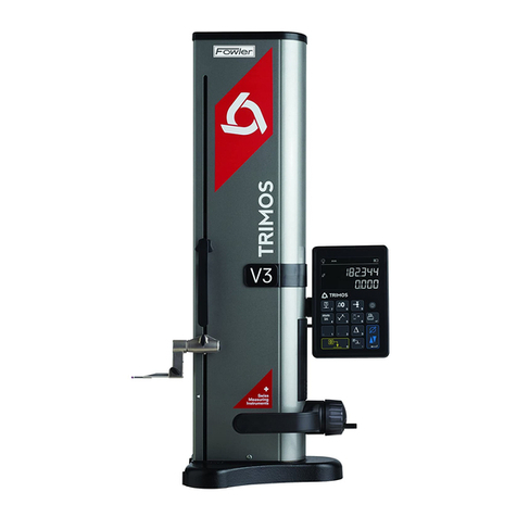
TRIMOS OPTIMA User manual

Dear customer, congratulations for choosing a TRIMOS measuring instrument. For more than 30 years,
our products have built up an excellent reputation in terms of quality, accuracy and longevity. For full
satisfaction with the present product, we recommend to read carefully this user’s manual.
尊敬的用户,感谢您选择TRIMOS测量仪器。30年以来,我们产品是质量,精度和长寿命的完美组合,
对于此型号产品,我们建议您使用前请仔细阅读用户手册!
English/China
译本 1.1 / 2006-02YJH
750 50 0023 00 1

Contents(目录)
1 Safety regulations(安全规则) ...........................................................................................................3
1.1 Important information(重要通告) .................................................................................................3
1.2 Security symbols (安全符号).............................................................................................................3
1.3 General warnings(普通警告)........................................................................................................3
2 Instrument description (仪器介绍)....................................................................................................4
2.1 Instrument construction(仪器构造)..............................................................................................5
2.2 Display unit(显示单元).................................................................................................................5
3 Getting started(开始).........................................................................................................................6
3.1 Packing list(包装目录)..................................................................................................................6
3.2 Setting up(安装)..............................................................................................................................7
4 Getting started(开始).........................................................................................................................9
4.1 Setting into operation and first measurement (第一次测量和操作时的设定)...............................9
5 Basic functions(基本功能)................................................................................................................11
5.1 Selection of the tool edge shape(选择一个刀具测量轮廓)..........................................................12
5.2 Adjustment of the measuring field size(调整测量范围).......... ..... ..............................................17
5.3 Tool spindle management(刀具主轴管理)..................................................................................18
5.4 Tool management (刀具管理).....................................................................................................20
5.5 On-line help (在线帮助)...............................................................................................................22
5.6 Advanced functions(高级功能)...................................................................................................22
6 Data transfer and printing (数据传输和打印)..................................................................................29
6.1 RS 232 ...........................................................................................................................................29
6.2 USB-A ............................................................................................................................................29
7 Application and adjustments (应用和调整)....................................................................................30
7.1 Positioning help (定位帮助).........................................................................................................30
7.2 New measurement (更新测量法)................................................................................................30
7.3 Continuous measurement (连续测量).........................................................................................30
7.4 Multi-level measurements of tool distances in Z(
刀具的Z轴方向的多级测量)...........................30
7.5 Accuracy of the vision system(显示系统的精确性)....................................................................31
7.6 Reset function (重启功能)..........................................................................................................31
7.7 Displacement handle(操作手柄).................................................................................................31
7.8 Locking of the tool spindle(刀具主轴锁定)..................................................................................31
7.9 Exchanging of the tool spindle (更换刀具主轴)...........................................................................32
7.10 Contrast / brightness adjustment of the tool vision screen (刀具显示屏的对比度/亮度调整).....32
7.11 Cleaning(清洁)............................................................................................................................32
8 After Sales Service(售后服务).........................................................................................................33
8.1 Complaints / Repairs(报修/修理)................................................................................................33
8.2 Agents(代理商)...............................................................................................................................33
9 Technical specifications(技术参数)...................................................................................................33
750 50 0023 00 2

1
Safety
regulations
(安全规章)
1.1 Important information(重要通告)
In order to prevent any damages due to a wrong manipulation, please read carefully the following instructions.
TRIMOS will not accept any responsibility in case of damages caused by inadequate use not in line with the
present manual.(为了防止错误的处理避免任何的损害,请小心地阅读下列各项指导。 TRIMOS 将不承担不按操
作说明所引起的任何后果)。
1.2 Security symbols(安全标志)
The following security symbols are used in this manual :
(下列的安全符号被用于这一本手册)
General warning, utilization advice(普通警告,建议使用)
Risk of electric shock(小心触电)
Electrostatic protection(静电保护)
1.3 General warnings(普通警告)
Protection against electrostatic interferences: 防止静电保护:
Static electricity can damage the electronic components of the instrument. In order to prevent this
type of damages, avoid any contact with the connector pins. 静电能损害工具的电子成份。 为了要
避免损害的这一个类型,避免与接口的任何探针接触。
Switch on:开关
The instrument should not be turned on unless all the electrical connections have been correctly and
completely performed. 除非所有的电连接正确而且完全地已经被运行,否则仪器不应该被打开。
In order to prevent any changes of the instrument performance or any accident, the instrument
should never be dismantled. 为了要避免任何性能改变或意外事件的变化,工具不应该私自拆开。
If, for any reason, the display units have to be opened, only authorized personnel is allowed to do
it. 如果,对于任何的理由,显示单元必须被打开,没有经认可的人员不允许做。
Do not expose the instrument, its components and accessories to rain or any projection of fluids.
Avoid penetration of foreign substances into the connectors and the instrument openings.
不要暴晒仪器, 它的成份和配件受潮或任何液体的沾染。避免外部物质的渗透进接口和工具之内
Don’t expose the vision system to direct sunlight or other important light source.
不要在阳光下或强光下暴露显示器
Do not cover or wrap the display unit during use. The unit must be kept well ventilated to avoid
any overheating. 在使用期间不要包裹显示器。 显示器一定被保持得好通风避免任何的过热
In case of problems with the instrument or any of its parts (no display, overheating, abnormal
smell), switch off the instrument immediately and disconnect the power supply. Please contact
your local TRIMOS agent. 假使工具的问题或任何其它部份 (没有显示,过热,不正常的气味),请
立刻切断仪器的电源。 尽快连络你当地 TRIMOS 代理人。
This is a high accuracy instrument. Particular care should be taken during its entire operational
lifetime. Pay special attention to the following specific points: 这是一个高精度仪器。 特别的照料
可以延长在它的整个操作寿命。 对下列的特性给予特别的注意:
- Use the instrument on a stable, flat and clean surface plate.使用一个干净整洁和平稳的桌子
- Avoid any shock to prevent the instrument from changing some or all of its performing characteristics.
在使用仪器期间尽量避免任何的振动
- Use the instrument in a vibration free area.在防震区域使用仪器
- Avoid exposure to direct sunlight and excessive humidity.避免阳光直射和受潮
- Avoid proximity of heating or air conditioning systems.避免过热或接近空调
- Respect the advised environmental conditions.注意周围环境情况
750 50 0023 00 3

2
Instrument
description
(仪器介绍)
4
3
2
7
6
5
1 45 46
38394044 43 42 41
3736
35
34
30
32 31
29
28
33
16171822 21 20 19
1514
101113 12
23
24
25
26
27
8
9
750 50 0023 00 4

2.1 Instrument construction
1. Handle for the displacement in both axis and locking device (movement locked/unlocked)
带按钮的操作臂手柄 (移动锁定/开启)
2. Camera(照相机)
3. Tool spindle(刀具主轴)
4. Instrument base(仪器底座)
5. Locking device for tool spindle system(刀具主轴锁定装置)
6. Positive locking of the tool spindle using an indexing system at 8 x 45°
(刀具主轴8 x 45°分度系统)
7. Light system(光源)
8. Tool outline display(刀具轮廓显示器)
9. Control and measurement unit (控制和测量单元)
2.2 Display unit(显示单元)
2.2.1
Tool
profile
display
screen
(刀具轮廓显示器)
10. Measuring zone(测量区域)
11. Angle 1(角度1)
12. Radius(圆角)
13. Reference lines (Reticule)(参考线十字)
14. Angle 2(角度2)
15. Tool profile(刀具轮廓)
2.2.2
Screen
for
measuring
value
display
and
tool
management
(测量值显示和刀具操作屏)
16. Menu of the different functions(多功能的菜单)
17. Time(时间)
18. Date(日期)
19. Horizontal axis measuring values(水平轴测量值)
20. Vertical axis measuring values(垂直轴测量值)
21. Identification of the vertical axis(垂直轴标志)
22. Identification of the horizontal axis(水平轴标志)
23. Identification of the measuring mode: radius / diameter(测量模式标志:半径/直径)
24. Identification of the measuring mode: absolute / delta / stop(测量模式标志:偏移/差值/停止)
25. Number of the tool spindle(主轴编号)
26. Description of the tool spindle(主轴规格)
27. Shape of the tool to be checked(刀具测量方式)
28. Description of the tool(刀具种类)
29. Number of the tool / number of measurement(刀具编号/测量编号)
30. Tool dimensions (horizontal axis, vertical axis, radius, angle 1, angle 2)
刀具参数(水平轴、垂直轴、刀尖圆角、角度1、角度2)
2.2.3
Keyboard
(键盘)
31. Displacement keys (cursor) 方向键(方向)
32. On/Off key (power ON / OFF) 开关键(动力ON/OFF)
33. Numerical keyboard(数字键)
34. Memory key (value display / delete) 存储键(数值显示/删除)
35. Data print-out function(数据打印功能键)
36. Data confirmation key (Enter) 数据确认键(ENTER)
37. Multi-function key 多功能键
2.2.4
Connectors
(连接器)
38. "Instrument" system connector(仪器系统连接器)
39. RS 232 male(RS232公)
40. RS 232 female(RS232母)
41. Not used(不使用)
42. USB A(USB A)
43. USB B(USB B)
44. Not used(不使用)
45. X axis (horizontal) (X轴水平)
46. Z axis (vertical)(Z轴垂直)
750 50 0023 00 5

3
Getting
started
3.1 Packing list(包装目录)
The standard equipment of the instrument includes the following items(工具的标准配置包括下列项目)
1. Instrument(仪器)
2. Display unit and screen on holder(在固定架上的显示单元和触摸屏)
3. Pen for touch screen(触摸屏操作笔)
4. AC adapter(电源适配器)
5. Power supply cable(电源线)
6. Installation diagram(安装指示图)
7. User’s manual(说明书)
8. Test certificate(测试证书)
9. Certificate of guarantee(保证书)
750 50 0023 00 6
If the instrument has been stored at a temperature below 5 °C, wait for a few hours before
unpacking to prevent the instrument parts from condensation. Condensation can affect sensitive
parts of the instrument. Keep the original packaging.
如果温度低于5°C,请等候几小时打开包装,防止冷凝,冷凝可能损害仪器的敏感部位。请保
留原包装。

3.2 Setting up(安装说明)
After unpacking, install the instrument as follows: (拆开包装后,按下列顺序准备安装)
1. Remove the transport bars.(移开运送固定螺栓)
2. Fix the 3 supporting pads.(安装三处支撑垫)
3. Position the instrument on a stable bench.
Be careful about not to damage the cables.
(将工具安放在稳定的台面上,小心不要压坏仪器的电缆线)
Static electricity can damage the electronic components of the instrument. In order to prevent
this type of damages, avoid any contact with the connector pins.
(静电会损害仪器的电子设备,要避免静电和连接器针头接触)
4. The display unit for the tool measurement/tool
management and the screen of the vision system are mounted together
on a support. Both units are connected with a cable, factory mounted.
(显示器已经安装,您将看到一个刀具轮廓显示屏和一个测量/操作显示屏安
装在一起,这两个可以用电缆连接,这些在出厂前安装好的)
5. Connect the horizontal axis (X) of the measuring
system.
(连接水平测量轴X到测量系统)
750 50 0023 00 7

6. Connect the vertical axis (Z) of the measuring system.
(连接垂直轴Z到测量系统)
7. Connect the instrument system cable to the display unit.
(连接仪器系统到显示单元)
8. Connect the 9 pin connector of the camera (CAM) to the
vision display unit.
(连接 9针的照相机连接器到道具显示器上)
Don’t connect the instrument power supply before having performed all electrical connections
correctly as described before.
(在没有正确连接完这些仪器的线缆之前,严禁接通电源)
9. Connect the mains cable of the charging unit (plug
located at the rear of the base).
(电源的插头在仪器底座的后面箭头所示位置)
Don’t connect the mains power supply (charging unit) to the display unit.
(不要将电源连接在显示器上)
750 50 0023 00 8

4
Getting
started
(开始)
4.1 Setting into operation and first measurement(第一次测量和操作时的设定)
1. To switch the power ON, press the On/Off key.
To switch it OFF, press the same key again until the power
is switched off.
(打开仪器,按ON/OFF键。关闭仪器,长按此键直到关闭)
2. The request to pass the references is displayed. Move slowly one of
the axis until an acoustic signal is heard. The reference has been
detected and the display starts counting. Proceed the same
way with the other axis.
(仪器询问通过参考点,由此,向一个方向缓慢移动操作臂直到听见吡
的一声响说明参考点已经发现,开始显示数值。同样的方法可以找到另
一个轴的参考点)
If no spindle has been selected or saved in the database, no measurement can be done. To
select or create a tool spindle data table, refer to the menu ″Tool spindle management″(§ 5.3).
(如果没有在数据库中选择主轴,则不能测量。选择或创建一个主轴,详见刀具主轴管理菜单5.3章)
Do not forget to take the reference of the selected tool spindle before performing any
measurement. (§ 5.3.5).
(在每次测量前不要忘记选择一个有参考点的主轴,详见5.3.5章节)
3. Position the tool into the spindle (将刀具装进主轴)
Before positioning the tool into the spindle, make sure that the tool cone surface is perfectly
clean and no burs are appearing.
(在测量之前,请仔细检查主轴和刀柄接触面是否清洁,因为任何污物都回造成测量数据不准确)
While positioning the tool into the spindle, be careful not to damage the cone.
(当安放刀柄时,不要碰撞高精度的主轴内锥面)
3. If the tool has been stored in the database, it can be recalled (§ 5.4.4).
If not, enter it to the database or ignore this step.
( 如果这个刀具数据已经保存,存储(参5.4.4章节)如果
不存储它可以跳过此项)
5. Press the key ″1″to unlock both axis movements and
displace the arm using the handle in order to position the tool profile
into the camera view field.
(按操作手轮上的这个按钮,可以轻松的开启测量臂的运动,将操作臂上
的照相机移到其刀具测量的部分)
750 50 0023 00 9750 50 0023 00 9

6. If it is not possible to clearly view the requested profile
contour, reduce the scale limits of the area of analysis
(§ 5.2).
(如果不能清楚地看到测量的刀具刃,可以选择一个较小
的测量范围 参5.2章节)
7. The vision system will select automatically the best tool
contour profile.
(显示系统将自动选择一个最好的刀具轮廓)
If the automatically selected profile does not correspond or cannot be measured, open the
menu ″Selection of tool contour profiles″(§ 5.1).
(如果软件不能确认这个刀具外形,你必须选择一个测量方式,去菜单选择一个刀具测量
方式 参5.1 章节)
8. Turn the tool slightly in both direction to be able to
determine the reversal point (max. value)
(慢慢来回旋转刀具用来确认刀具的最大直径,最大值)
9. The tool measurement values will be displayed, if the
tool has been stored in the database. Save the values by
pressing the key shown at the right side.
(刀具测量值将直接显示出来。如果将这个刀具测量数值保存在
这个数据库中按这个按钮即可保存数据)
10. To print the measured values on a printer connected to
the RS232 port, press the corresponding key (§ 6.1).
(按这个打印键,允许将刚才测量的刀具数值通过
RS232数据接口打印,详见6.1)
750 50 0023 00 10

5
Basic
functions
(基本功能)
Selection of the tool edge shape
(选择刀具测量方式)
Adjustment of the analysis range
(调整测量范围)
Tool spindle management
(主轴管理)
The menu of the basic functions is shown at the
right side of the touch screen.
(基本的功能菜单在触摸屏的右端边显示) Tool management
(刀具管理)
On-line help(在线帮助)
Advanced functions(高级功能)
The display zone is divided into several tactile zones. These allow rapid access to measuring modes, tools
and adaptors.(这个触摸显示屏被分为几个独立的触摸区域。这样可以迅速的进入测量模式,刀具和主轴)
Absolute measuring modes
绝对测量模式
/ delta / radius stop /diameter
/差值/停止/直径
Adaptors management
(主轴管理)
Tool shape selection
(刀具外形选择)
Tools management Clear tool data shown
(刀具管理) onthedisplay
(刀具测量详细信息)
not in the databas
(不在数据库)
750 50 0023 00 11

5.1 Selection of the tool edge shape(选择刀尖外形)
In the standard measuring mode, the vision system selects automatically the most appropriate tool edge
shape of the tool, which appears in the vision field.(在标准的测定模态中,当刀尖在视觉领域中出现
时,视觉系统自动选择最适当的刀具外形测量方式。)
If the tool edge shape has to be selected manually, activate
the corresponding symbol.
(如果工具边缘形状必须用手选择,点击对应的符号。)
The menu, which opens shows different kind of tool edge shapes.
Select the requested one by touching the corresponding symbol.
(菜单指引不同类型的刀具外型形状。 点击对应的符号选择。)
Line measurement of line 1 (第1线测量法)
Line measurement of line 2 (第2线测量法)
Point measurement in X direction (X方向端点测量法)
Point measurement in Z direction (Z方向端点测量法)
Line measurement of line 1 and point measurement in X direction
(第1线和X方向端点测量法)
Line measurement of line 2 and point measurement in X direction
(第2线和X方向端点测量法)
Line measurement of line 1 and point measurement in Z direction
(第1线和Z方向端点测量法)
Line measurement of line 2 and point measurement in Z direction
(第2线和Z方向端点测量法)
Line measurement of line 1 and 2(第1线和第2线测量法)
Line measurement of line 1 and 2 and point measurement in X direction
(第1线第2线和X方向端点测量法)
Line measurement of line 1 and 2 and point measurement in Z direction
(第1线第2线和Z方向端点测量法)
Point measurement in X and Z direction(X和Z方向交点测量法)
Fixed reticule(固定标线)
Activates /deactivates the circle measurement of the contour(激活/解除 轮廓圆角测量法)
Activates /deactivates the angle measurement of the contour(激活/解除 轮廓角度测量法)
Measure a Z-value related to a given X-value(测量一个给定X值相关的Z值)
Measure a X-value related to a given Z-value(测量一个给定Z值相关的X值)
750 50 0023 00 12

5.1.1
Principle
of
the
analysis
of
the
contours
(轮廓分析的原则)
The system includes two measuring modes to analyze the contour of an object:
(系统包括二个测定的模式分析物体的轮廓:)
- The point measurement(端点测量法)
- The line/angle measurement(线/角测量法)
Point measurement(端点测量)
The point measurement allows the performance of the maximum elongation value of a tool contour in respect
to the corresponding axis.(端点测量允许对对应的轴在考虑最大一个刀具轮廓的延伸值的关系。)
The system determines automatically the elongation position and adjusts the vertical and horizontal line to this
position. (系统自动地确认延伸位置并且调整垂直和水平线到这一个位置。)
Line/angle measurement(线/角测量法)
The line measurement allows to determine and to analyze one or more straight sections of the contour of the
object to be checked. (线测量允许确认并且分解一个或更多要检查的物体轮廓的直区段。)
The lines are located directly at the right side section of the contour of the object to be measured. The result
of the image analysis and the actual position of the optical unit will be taken over for the measurement
performance of the object. (线在物体轮廓的右边区段被直接地被测量。 结果图像分析和光学的单位真实
位置将会被为物体的测量表现接管。)
5.1.2
Information
about
the
angle
values
(关于角度测量的介绍)
The angle information is defined as follows: (角度数据依下列各项被定义:)
a) Enclosed angle(被附上的角度)
b) Angle, starting from the nearest measuring line towards
the tool edge contour. a b
角度, 来自最近的测量线向刀具轮廓方向。
+ 4
5
°
-
4
5
°
- 4
5
° + 4
5
°
The angle values between the nearest measuring line and the
tool edge contour (b) are always in the range of ± 45 °
referring to the reticule. Its signs change according to a half
+45° -
4
5
°
angle of a quadrant (see picture at the right side).
在最近的测量线和工具轮廓 (b) 之间的角度值总是在
十字线的 ± 45 ° 的范围中。 它的标记依照四分圆的
-45°
+
4
5
°
一个一半角度的变化.( 见到在右边的照片)
750 50 0023 00 13

5.1.3
Detailed
description
of
the
measuring
methods
(测量方法的详细介绍)
Line 1
Line measurement of line 1(第1线测量法)
Determines the line 1.(确定第1线)
(Counter clockwise transition of light/dark in the status window)
(在窗口显示为由亮到暗逆时针转变)
Line 2
Line measurement of line 2(第2线测量法)
Determines the line 2.(确认第2条线)
(Counter clockwise transition of dark/light in the status window)
(在窗口显示为由暗到亮逆时针转变)
Point
X
Point measurement in X direction(X方向端点测量法)
Determines the maximum elongation value in X direction.
(确认X轴方向最大数值)
Point Z
Point measurement in Z direction(Z方向端点测量法)
Determines the maximum elongation value in Z direction.
(确认Z轴方向最大数值)
Line measurement of line 1 and point measurement in X direction
(第 1 线和X 方向的端点测量法)
The vertical axis is tangent to one point and represents the reference line.
The line 1 passes the origin of the reticule.
(对端点垂直的轴是接触的而且表现叁考线。)
(第 1 线通过交叉的原点。)
The orientation of the contour is at its optimum when the arrows are positioned
exactly in the center of the adjustment bars. Point
X
Line 1
(刀尖轮廓线处于屏幕的正中心时候是最好的。)
Line 2 Point
X
Line measurement of line 2 and point measurement in X direction
(第 2 线和X 方向的端点测量法)
Determines the maximum elongation value in X direction and line 2. The results
refer to the intersection.
(确定 X 方向和第 2线的最大延伸数值。 结果就是交叉点。)
750 50 0023 00 14

Line measurement of line 1 and point measurement in Z direction
(第1线和Z方向端点测量法)
Determines the maximum elongation value in X direction and line 1. The results
refer to the intersection.
(确认第1线和X方向最大值延长线上,结果就是交点)
Line 1
Point Z
Line measurement of line 2 and point measurement in Z direction Point Z Line 2
(第2线和Z方向端点测量法)
The vertical axis is tangent to one point and represents the reference line.
The line 2 passes the origin of the reticule.
(对端点垂直的轴是接触的而且表现叁考线。)
(第 2 线通过交叉点。)
The orientation of the contour is at its optimum when the arrows are positioned
exactly in the center of the adjustment bars.
(刀尖轮廓线处于屏幕的正中心时候是最好的。)
Line measurement of line 1 and line 2(第1线和第2线测量法)
Determines the intersection of the two reference lines (line 1 and line 2).
确认两个参考线的交点(线 1和线 2)
Line 2
Line 1
Line measurement of line 1 and 2 and point measurement in X direction Line 1 Line 2
(第1线和第2线和X方向端点线的测量法)
The vertical axis is tangent to one point and represents the reference line. The
intersection of the two other reference lines is located on the horizontal axis.
(对垂直的轴接触的端点叁考线。其他二条叁考线的十字路口位于水平的轴之上。)
The orientation of the contour is at its optimum when the arrows are positioned
exactly in the center of the adjustment bars.
(刀尖轮廓线处于屏幕的正中心时候是最好的。)
Point
X
Line 1 Line 2
Line measurement of line 1 and 2 and point measurement in Z direction
(第1线和第2线和Z方向端点线的测量法)
The horizontal axis is tangent to one point and represents the reference line. The
intersection of the two other reference lines is located on the vertical axis.
(对水平的轴接触的端点叁考线。其他二条叁考线的十字路口位于垂直的轴之上。)
The orientation of the contour is at its optimum when the arrows are positioned
exactly in the center of the adjustment bars.
(刀尖轮廓线处于屏幕的正中心时候是最好的。)
Point Z
Point X Point Z
Point measurement in X and Z direction(X 和 Z 方向的端点测量法)
The horizontal axis and the vertical axis are both tangent around one point and
represent the reference lines.
(水平的轴和垂直的轴在附近都是切线指出而且表现叁考线。)
The orientation of the contour is at its optimum when the arrows are positioned
exactly in the center of the adjustment bars.
(刀尖轮廓线处于屏幕的正中心时候是最好的。)
750 50 0023 00 15

If the vision system is not able to perform any measurement of the identified contour, no
reference line will be displayed on the screen and no icon shown in the status window.
(如果视觉系统无法运行任何被识别的投影的测量,没有叁考线将会在荧屏和在状态窗户中被
显示的没有图标上被显示。)
Fixed reticule(固定坐标)
By activating this function, the vision system acts like a projector. Which means that the displayed value
for each axis corresponds to the position of the reticule’s origin.
(按动这一个功能,视觉系统看起来像一个投影器一样。 哪意谓给每个轴的显示值符合坐标位置。)
Adjustment bars are provided for both directions in this operating mode. The pointer in the X adjustment
bar gives the contour’s positive or negative deviation from the measuring line in the X direction, the Z
adjustment bar does the same in the Z direction. The adjustment bars are divided into setting ranges
(segments). These areas describe the contour's distance from the measuring line.
(这个模式提供两个方向的调整聚焦条。 X调整的聚焦条提供投影的实在或
否定来自 X 方向的测定线偏离,Z 调整聚焦条和Z 方向的一样。 调整聚焦被
区分为设定范围 (片段)。这些区域描述来自测定的线投影的距离。)
±
(
16 - 60
)
µm
±
(
4 - 15
)
µm
;
± (0 - 3)
The rotation of the measured object in its housing allows you to determine its maximum edge. The
position of its maximum edge than matches with the adjustment plane.
(旋转主轴允许你确定刀尖的最大边缘。 它的最大值的位置是调整平面的刀尖。)
Activating and deactivating the circle (radius) in the contour
启动和解除那轮廓的圆角 (半径)
Has this function been activated, the system tries to identify one of the contour of the object as a radius.
The radius is marked as a circle and the radius value is indicated in or at the side of the circle. If the
radius is smaller than 0,3 mm or greater than 8 mm, no circle will be displayed.
(点击选取这个功能, 系统尝试确认物体的轮廓之一为一个半径。
半径被作记号如一个圆角和半径价值被指出在或在圆周的边。如果
半径超过 8 毫米是比 0,3 毫米小的或大,没有圆周也将被显示。)
Activating and deactivating the angle measurement
(启动和解除角度测量)
Has this function been activated, the system tries to measure the angles of the shown contour
The angle lines are displayed and the values are shown on the screen.
(当激活这个功能, 系统测量要显示的轮廓的角度角度线被显示,而且数值在荧屏上显示)
To close the toll shape selection menu without doing any changes, press one of the symbols shown at
the right side.
(关闭形状选择菜单不会有任何的变化, 按这个右边被显示的符号之一。)
The same is valid for the other menus
(一样的对其他菜单也是有效的)
750 50 0023 00 16

Measuring a X or Z value with a default value(测量一个X或Z值当一个缺省值)
Select this icon out of the dialog of the measuring functions
(从测定的功能会话选择这一个图标)
You will see this input dialog to fill in the known value. Please
fill in the default X-value ort he default Z-value.
(你将会见到这输入会话填写已知的数值。 请填写缺省的
Z 的 X 价值的)
After you filled in the default value, please select the one of
the two measuring functions
(在你填写假设缺省值之后,请选择二中的一测定功能)
You fill in a default X-value and the vision system will measure
the related Z-value.
(你填写缺省值 X-值和视觉系统将会测量相关的 Z-值。)
You fill in a default Z-value and the vision system will measure
the related X-value.
(你填写缺省值 Z-值和视觉系统将会测量相关的 小 X-值。)
After you select one of the two measuring functions, you will
see the edge finder screen. The display window looks like a practice target,
the center represents the measuring point. you will see a horizontal or a
vertical line depending on the measuring function you choose. Move the
measuring arm towards the center to obtain a correct positioning of the
camera.
(在你选择一或二测量功能之后,你将会见到边缘探测器荧屏。显示窗户看起
来像一个练习目标一样,中心表现测定的点。你将会见到水平线或一条垂直
线依靠你选择的测定功能。向中心移动测臂获得照相机的一个正确定位。)
5.2 Adjustment of the measuring field size(调整测量范围尺寸)
By touching the symbol, shown at the right side, the size of
the measuring field can be adjusted.
(点击这个符号, 在右边显示,测定的领域大小能被调整。)
This function may be particularly useful when checking complex
profiles. Adjust the measuring field to the contour to be checked
and position it inside the field.
(这一个功能当检查复杂的轮廓时是非常有用的。 调整测定的领域
大小到被检查轮廓并且放到它范围之中。)
750 50 0023 00 17

5.3 Tool spindle management(刀具主轴管理)
This function allows the management of the tool spindles used.(这一个功能允许用于刀具主轴的管理)
To open this management menu, touch the symbol shown at the right side.
(打开这个管理菜单, 按右边显示的符号。)
a) Creating a new tool spindle data file(新建一个刀具主轴数据文件)
b) Modifying a stored data file of a tool spindle
(更改一个保存的刀具主轴数据文件)
c) Deletes stored data of a tool spindle
(删除一个存储的刀具主轴数据)
d) Recalls a required tool spindle(取消一个必需的刀具主轴)
e) Performing the reference check and storage of the used tool spindle a b c d e f
(演示检查参考点和存储使用的刀具主轴)
f) Print-out of the tool spindle list(打印刀具主轴目录)
5.3.1
Creating
a
new
tool
spindle
data
file
(新建一个刀具主轴数据文件)
Getting started(开始)
Open the required window by touching the symbol shown at the
a b
right side. The following menu will be displayed:
(打开必需窗户点击在右边被显示的符号。下列的菜单将会被显示:)
c
a) Number of the tool spindle(刀具主轴编号)
d
b) Name of the tool spindle(刀具主轴名称) e
c) Position of the vertical reference ball(垂直参考球的位置) f
d) Position of the horizontal reference ball (水平参考球的位置) g
e) Measurement direction of the axis(轴的测量方向) h
f) Identification of the axis(轴的确认)
g) Adapter for radius measuring only(半径测量模式)
h) Adapter for diameter measuring only(直径测量模式)
: Symbol for the horizontal axis(水平轴标志)
: Symbol for the vertical axis(垂直轴标志)
Data input and storage(数据输入和存储)
The data input is performed using a touch screen. It is also
possible to activate the fields using the cursor keys.
(数据输入需要使用触摸屏。同样也可以使用光标键激活的领域)
- The tool spindle number is indicated by default (a). This
number can be changed. 刀具主轴数字被预先设定地指出
(a)这一个数字能被改变。
- Enter a description of the tool spindle by touching the field
(b). A virtual keyboard will be displayed and allows entering a text.
点击输入刀具主轴的描述(b)一个虚拟的键盘将会被显示并且允许进入一个本文。
- The position of the reference balls (c and d) is mentioned on the test certificate supplied with the tool
spindle. 叁考球(c和d)的位置在提供刀具主轴的测试证书上被提到。
- Select the measurement direction for each axis (e).
选择各自轴的测量方向(e)
- S
elect the identification of the axis (f) 选择各自轴的图标(f)
Saving of data(数据保存)
After completion of the data input, save those by touching the
symbol shown at the right side.
(在数据输入完成之后, 按在右边被显示的符号保存它们。)
5.3.2
Modifying
a
stored
data
file
of
a
tool
spindle
(更改一个保存的刀具主轴数据文件)
To change data of a tool spindle, touch the symbol shown at
the right side.
(更改一个刀具主轴的数据, 按右边显示的图标)
The window, which opens is treated the same way as the one
for the data collection creating a tool spindle.
(窗口, 打开一个处理过的新建刀具主轴的数据收集。)
750 50 0023 00 18

5.3.3
Deleting
stored
data
of
a
tool
spindle
(删除一个存储的刀具主轴数据)
To delete data, select the required tool spindle data line and
touch the symbol shown at the right side.
(为了删除数据, 选择删除的刀具主轴数据并点击在右边被
显示的图标。)
Confirmation or not of the deleting procedure. ou
(确认或不删除)
5.3.4
Use
of
a
tool
spindle
(使用一个刀具主轴)
This function allows the selection of the tool spindle to be used.
(这一个功能允许刀具主轴的选择使用)
Select the corresponding data line and confirm by touching the
symbol shown at the right side.
(点击在右边显示的图标选择对应的数据而且确定。)
Note:(注意)
After each exchange of a tool spindle, a new reference check
must be performed (see § here-after).
更换一个刀具主轴之后,新的叁考点必须检查并被运行。 (见到 §后)
5.3.5
Checking
of
the
reference
at
the
tool
spindle
(校准一个刀具主轴参考点)
To be able to check the reference of a tool spindle, touch the
symbol shown at the right side. Bring the reference balls in
position,as near as possible to the fixed reticule and confirm
to pass on to the next sequence.
(为了能够检查刀具主轴的叁考点, 点击在右边显示的图标。
对叁考球位置, 尽可能接近到固定的十字坐标而且确定通过
下一顺序)
Turn the tool spindle slightly a few degrees in both directions
to determine the maximum diameter value. Confirm by touching
the symbol shown at the right side.
(来回慢慢转动主轴确认最大直径。点击在右边显示的图标确定。)
5.3.6
Print-out
of
the
tool
spindle
list
(打印一个刀具主轴目录)
By touching the symbol shown at the right side, the tool
spindle list will be transferred and printed out (printer connected
to the USB-A port (see § 6.2)).
点击在右边显示的图标,刀距主轴目录将会被调取而且印刷出。
(打印机连接到USB-A (见到 § 6.2))
750 50 0023 00 19

5.4 Tool management(刀具管理)
This function allows the creation and the management of the tool data. To open the tool management menu,
touch the symbol shown at the right side.(这一个功能允许创造和管理刀具
数据。打开刀具管理菜单,点击在右边显示的图标。)
a) Saving tool data (保存刀具数据)
b) Modifying the tool data (修改刀具数据)
c) Deleting tool data (删除一个刀具数据)
d) Recalling a tool (取消一个刀具)
e) Filter to search a tool (搜索一个刀具)
f) Print-out of the tool list (打印一个刀具目录)
a b c d e
f
5.4.1
Saving
tool
data
(保存刀具数据)
Getting started(开始)
By touching the symbol shown at the right side, following menu will be displayed:
(开始点击在右边显示的图标,跟随菜单将会显示:)
a) Number of the tool (刀具编号)
b) Description of the tool (刀具备注) a b
f
e
c) Key to select the tool family (选择一个刀具种类键)
d) Key to select the tool type (选择一个刀具类型键)
e) Number of the tool type (刀具类型编号)
f) Picture of the tool type (刀具类型图片)
d
c
Data input(数据输入)
The input is done using the touch screen board.(通过触摸屏输入数据)
- The tool number is proposed by default (a). It is possible to modify it.
刀具序号被预先设定。(a)它是可能修改的。
- To enter the description, click on the corresponding field(b).
进入描述,在对应的区域(b)上按.
- To select the tool family, click on the arrows (c).
选择刀具种类, 在箭头 (c) 上按
- To select the tool type, click on the arrows (d).
选择刀具类型, 在箭头 (d) 上按
Note:(注意)
The list of tool types is presented in attachment A. (刀具类型的目录在附件A中呈现)
Saving data(保存数据)
After having completed the fields, save the data by touching
the symbol shown at the right side.
(在完成数据输入之后,点击在右边显示的图标保存数据。)
5.4.2
Modifying
the
tool
data
(修改一个刀具数据)
To modify tool data, touch the symbol shown at the right side.
(为了修改刀具数据, 点击右边显示的图标)
The displayed window will be treated the same way as the
one for saving tool data.
(可以用相同类型的刀具图片作为刀具数据存储的显示的窗口)
750 50 0023 00 20
Table of contents
Other TRIMOS Measuring Instrument manuals
Popular Measuring Instrument manuals by other brands

Femtochrome
Femtochrome FR-103MN instruction manual
KERN
KERN DLB 160-3A operating instructions
Associated Research
Associated Research HYPOT III 3705 Operation and service manual
AST
AST Peva-450I operating manual
geo-FENNEL
geo-FENNEL S-Digit multi+ user manual
National Instruments
National Instruments PXIe-4162 Getting started guide
