Trine 4100 Electric Strike User manual
TRINE 4100
THE ONE BOX SOLUTION
FOR CYLINDRICAL AND MORTISE LOCKS
Congratulations on the purchase of this quality TRINE security
product. This product has been designed to install easily,
perform reliably, and provide years of trouble free security.
BEFORE PROCEEDING
with your installation, please review the
following list of features. If you have any questions after reading
this document please call TRINE's TECHNICAL SUPPORT (718)
829-2332 EXT. 447, or visit the TRINE Web site at
www.trineonline.com
1440 Ferris Place l Bronx l New York l 10461
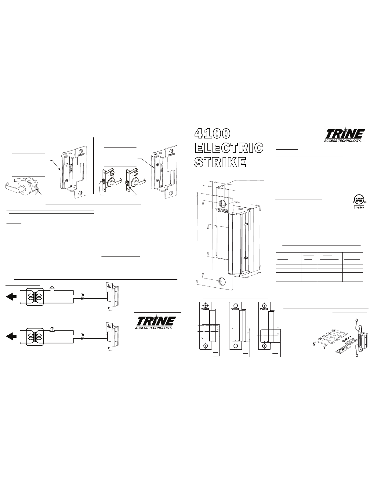
4100
ELECTRIC
STRIKE
INSTALLATION INSTRUCTIONS
CC Faceplate
(centered opening)
The 4100 is WH recognized for:
Class A, 3 Hour Single door / frame configuration
- UL10C, Fire Tests of Door Assemblies
- UBC 7-2, Uniform building Code
- CAN4 S104,
Standard Method for Fire Tests of Door Assemblies
NFPA 252 -
Issue: 1999/01/01 Standard Methods of Fire Tests of Door Assemblies
NOTE: WH fire listing is void when using fail safe action.
ANSI/BHMA A156.5 - 1992 - 4-7/8" x 1-1/4" Fits
Cutout Specification A115.1 (with Slight Jamb Modification)
BHMA - Grade 1
TROUBLESHOOTING THE COMPLETED INSTALLATION:
WIRING DIAGRAMS
DO NOT APPLY AN OVER VOLTAGE OF MORE THAN 10%
OVER THE RATED OPERATING VOLTAGE OF THE STRIKE OR
THE SOLENOID WILL BE DAMAGED
SYMPTOM: Electric release is not actuating:
1. Verify proper voltage is present AT THE STRIKE. If voltage is
present, the strike may have been affected during the
installation, or dirt or debris may be preventing proper
operation. Ensure that all moving parts are clean. DO NOT
LUBRICATE THE SOLENOID.
2. If voltage IS NOT present:
· Verify Circuit breaker is on
· Verify voltage at the transformer/power supply output.
· Verify that there are no additional, external switches or
devices which may be interrupting your circuit.
· Check for damaged wiring or bad wire splices.
SYMPTOM: Door will not open but strike is working
· First, check to see if the electric strike works properly
while the door is open.
· Check for proper lock-latch engagement
· Check for pressure from the door on the electric strike
by following these steps:
Push the door from the outside, try and relieve the bolt
to latch pressure and actuate the 4100. While the
4100 is unlatched swing the door open. If the door
opens, then the bolt maybe applying pressure to the
latch. Adjust the position of the 4100 to relieve the
pressure.
Possible remedies include:
1. Re-adjust door closer.
2. Remove door silencers.
3. Remove, or trim, weather stripping around the door.
4. Adjust electric strike position if possible.
5. Correct excessive warping of door.
USING THE LATCH SPACER SHIMS (CONTINUED...)
For locks not aligning to the vertical center of the strike, mount
the shims as shown below. Most if not all mortise locks will
work with the latch shims mounted this way.
Mount the shims with the
steps positioned away from
the top of the latch like this.
Auxilliary
Deadlocking Trigger
PHONE: (718) 829-2332
FAX: (718) 829-6405
1440 FERRIS PLACE
BRONX, NY 10461
email: customerservice@trineonline.com
website: www.trineonline.com
4
Current Power
Voltage Draw Consumption Resistance
12DC .240 A 2.90 W 50 Ω
24DC .114 A 2.74 W 210 Ω
12AC
@ 50-60Hz
.210 A 2.50 W 50 Ω
16AC
@ 50-60Hz
.281 A 4.48 W 50 Ω
24AC
@ 50-60Hz
.420 A 10.08 W 50 Ω
4100 ELECTRICAL CHARACTERISTICS:
4 7/8"
4 1/8"
1 3/4"
1/4"
25/32"
1 1/4"
3/4" CAVITY DEPTH
1 5/8"
3 3/8"
1 3/8"
Mount the shims with the steps
positionedaligned with the top
of the latch like this.
This position will ensure that the cylindrical
lock's auxilliary trigger will function properly.
USING THELATCH SPACER SHIMS
The latch spacer shims are used to make adjustments to
minimize the space between the door's inside face and the
door stop or reduce door play. For cylindrical locks aligning to
the vertical center of the strike mount
the shims as shown below.
Auxilliary Trigger
OPERATING TEMP RANGE: -20°C TO +40°C
DO NOT APPLY AN OVER VOLTAGE OF MORE THAN 10%
OVER THE RATED
OPERATING VOLTAGE OF THE
STRIKE OR THE SOLENOID WILL BE DAMAGED.
When removing the connector andusing the wires direct;
Red & Blue Wire accepts 12DC & 12-16 AC,
Brown & Blue Wire accepts 24DC.
24V DC OR 12V DC
TRANSFORMER
TO 120V AC LINE
PUSH
BUTTON
NORMALLY
CLOSED
+
-
FAIL-SAFE
ELECTRIC STRIKE
USE THE PROPER
CONNECTOR 12VDC OR 24VDC
ASSEMBLY FOR
THE 4100 STRIKE
Cannot use AC in Fail Safe Configuration
24V DC OR 12V DC TRANSFORMER
TO 120V AC LINE
PUSH
BUTTON
NORMALLY OPEN
+
-
USE THE PROPER
CONNECTOR 12VDC OR 24VDC
ASSEMBLY FOR
THE 4100 STRIKE
For AC use the 12 VDC connectors
For 12 - 24 VAC use 50-60 Hz
FAIL-SECURE
ELECTRIC STRIKE
V. 14.0814
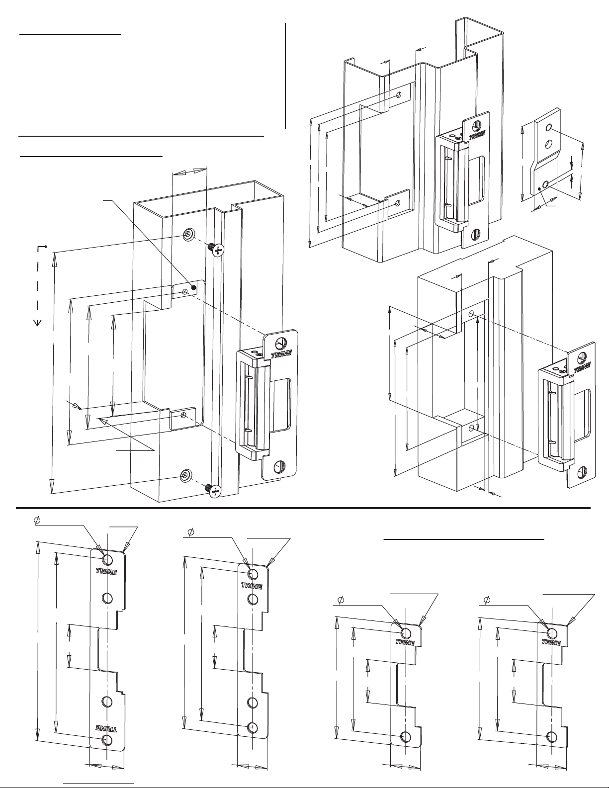
FACEPLATE AND OFFSET DIMENSIONS:
CAVITY
C
L
STRIKE
C
L
1 1/64"
1 11/32"
CAVITY
C
L
STRIKE
C
L
29/32"
1 11/32"
STRIKE
C
L
CAVITY
C
L
19/32"
1 15/32"
MHO MMO MLO
1 -(1) 4100 Electric
Strike Mechanism
2 -(4) Faceplates with Openings (CC, MHO, MMO, MLO)
3 -(2) #12-40 x 1 inch Philips Mounting Screws
4 -(2) #12-40 x 1 inch Torx®Security Mounting Screws
5 -(2) Quick Connect Socket &
Wire Assembly 12VDC
& 24VDC Version
6 -(2) Sealed Crimp
Connectors
7 -(2) Latch Spacer
Shims & (2) Mounting Screws
8 -(1) Frame Trim Skirt & (2) Screws
WHAT'S IN THE BOX:
4100 OPTIONS:
4100RS - FAIL SAFE CONFIGURATION
4100LB - LATCH BOLT MONITORING
4100RSLB -
FAIL SAFE/LATCH
BOLT MONITORING
BZ-12 - 12VDC Piezo Buzzer
BZ-24 - 24VDC Piezo Buzzer

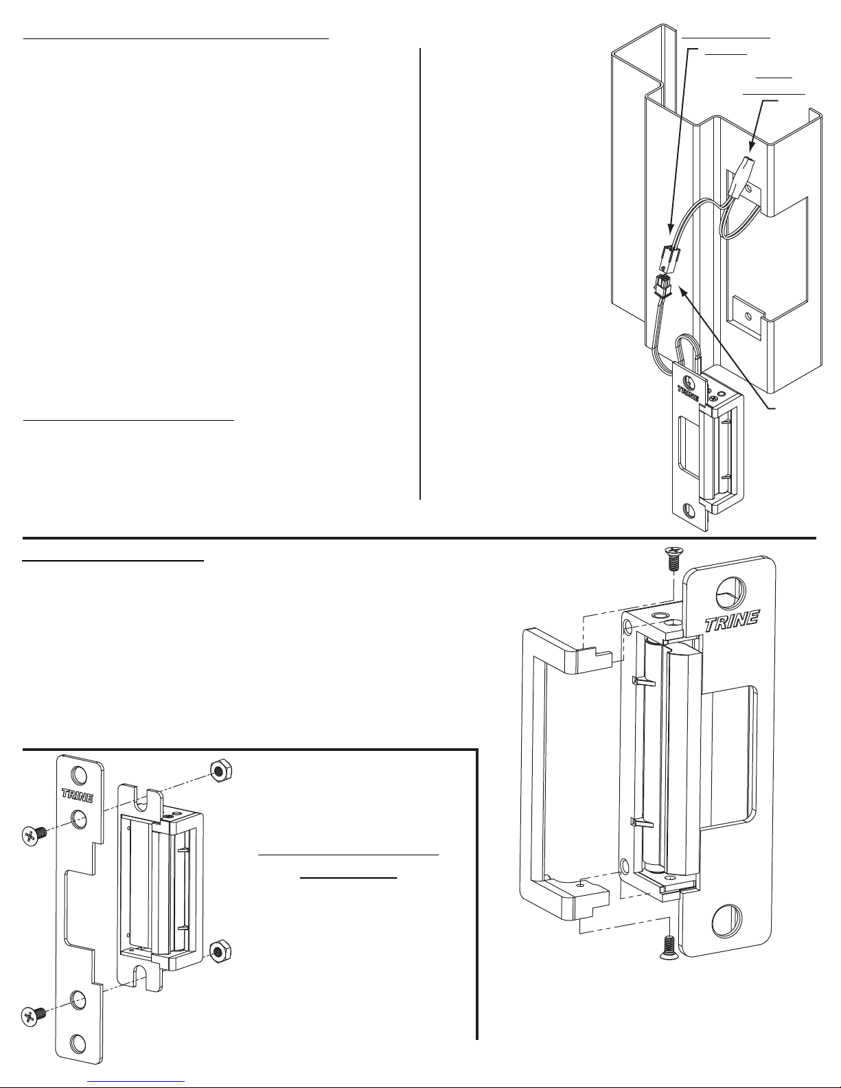
INSTALLING THE4100 STRIKE:
NOTE: The 4100 electric strike has two terminal wires to supply power to
two separate solenoids.
USE THEBOTTOMWIRE LEADS ONLY.
1. Prepare door frame as shown on page 2 (based on frame type).
2. Pull the switched power wires to the door frame. (Caution: Connect the
power ONLY as the last step.)
RECOMMENDED PRE-INSTALLATION CHECK:
1. Determine that the door swings without interfering
with jamb or sill; the door must operate properly in
order for the system to providebest results.
2. The door must be equipped with a door closer and
the door closer "latch mode" must hold door in a
completely closed position in order to avoid the lock
latch from applying pressure against the releasing
latch portion of the electric strike.
3. Electrical wire connections must be completed and
ready to be terminated inside the frame.
4. Confirm that the power line in the frame is the
correct voltage and that the switch works properly.
5. Confirm proper clearance exists between the end of
the lock latch and jamb.
6. The faceplate opening used on the electric door
strike must be centered with lock latch centerline
when itisinstalled on the doorjamb.
7. For best installation results, the door frame must be
reasonably flat and straight. 3
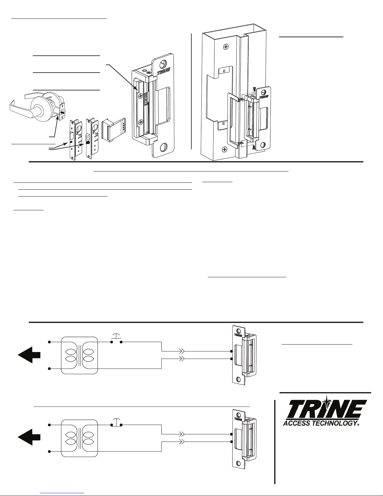
COMPATIBLE LOCKSETS:
CC: Centered Cylindrical (Reference
HES®
J faceplate)
Cylindrical Locksets up to 3/4" throw and all locksets
center linedbolts: Corbin Russwin
®
Security Bolt, Weiserbolt
®
.
MHO: MortiseHighOffset (Reference
HES®
KM faceplate)
Accurate
®
,Arrow
®
, Best
®
, Corbin Russwin
®
, Falcon
®
(1992MSeries),
Sargent
®
(7800,8200 & 9200 Series), Yale
®
(8800).
MMO: Mortise Medium Offset (Reference HES®K faceplate)
Baldwin
®
, Marks
®
, PDQ
®
.
MLO: Mortise Low Offset (Reference HES
®
KD faceplate) Jackson
®
,
Sargent
®
(7700 & 8100), Schlage
®
(L Series), Yale
®
(8700).
Additional Faceplates:
CCRD - 4-7/8” x 1-1/4“Centered Cavity with Radiused Corners
CRD7 - 6-7/8” x 1-1/4“ Tall Centered Cavity with Radiused Corners
CRD8 - 7-15/16” x 1-7/16“ Tall Centered Cavity with Radiused Corners
CRD9 - 9” x 1-1/4“Tall Centered Cavity
Plug the bottom
terminal of the strike
to the quick connect socket.
The top terminal is not
used. Put electrical tape
over it, tuck it into the
hollow of the frame or
trim it off if there is no
room in the frame.
Quick Connect
Socket
Crimp
Connector
3. Carefully choose the quick connect socket to match the required
voltage. The quick connect sockets are labeled 12VDC (Blue Wire) or
24VDC(White Wire).
4. Use the crimp connectors to terminate the ends of the quick connect
socket to the power wires coming out of the frame.
5. Connect the strikes bottom terminal to the quick connect socket.
6. Tuck the wires inside the door frame.
7. Install the electric strike into the door frame
8. Connect the power supply and turn power on.
9. Test your system.
Figure #2b
2
3 3/8"
1 3/8"
4 7/8"
1 17/64"
3/16"
3 11/16"
4 1/8"
FRAME PREPARATION
CC, MHO, MMO
ON HOLLOW
METAL FRAME
MLO
ON HOLLOW
METAL FRAME
(note 7/8” top
dimension)
Use the
Premium Trim Skirt
to clean up your
cutline (see pg 4)
Use the
Premium Trim Skirt
to clean up your
cutline (see pg 4)
Dead Locking
Trigger Trapped
ON WOOD FRAME
3 3/8"
4 7/8"
4 1/8"
1 17/64"
1 3/8"
7/8"
1 3/8"
3 3/8"
4 7/8"
1 17/64"
4 1/8"
PREMIUMTRIMSKIRT FOR THE 4100
USING THETRIMSKIRT
The skirt can be used to clean up the cut line
of the frame face during installation. The
Trim Skirt comes with 2 screws for fastening
to the top and bottom of the 4100.
Available in 6 architectual finishes: US32D,
US32, US3, US4, US10, US10B to match the
finish of the electric strike and faceplates.
FLUSH TO FRAME
If the 4100 electric strike does not mount flush to the rabbet of the frame,
use the enclosed shims to correct this condition. There are two ways of
mounting the shim; 1) between the strike mechanism and the faceplate as
shown in figure #2 or 2) between the frame mounting tab and the strike
mechanism as shown on figure #3.
WITH SOME LOCKING MECHANISMS
We have included different kinds of shims and trims to help fix problems
that are encountered in the field whileinstalling the 4100.
Here for example is a mortise lock with an anti-friction bolt and dead
locking trigger with sharp edges see Figure #1. Depending on the mounting
relationship of the strike and the lock, the dead locking trigger can wedge
between the faceplate and the latch keeper as shown on Figure #2a & 2b.
This can create a pre-load condition on the latch keeper which will prevent
the strike from unlocking.
Use the latch shim as shown on Figure #3a & 3b to prevent the dead
locking trigger from getting trapped between the latch keeper and the
strike faceplate. The faceplate must be notched to clear the latch
shim (see Figure #3a).
CCTS
If retrofitting for the electric strikes listed below, a separate Skirt
may be used to cover the gap left in the frame.Note: Specify the
finish of the CCTS so it matches the 4100 you have.
H.E.S.® 1006, Folger Adams® 712/732, Von Duprin® 6200 Series,
or Trine EN Series Strikes
Figure #2a
Figure #3bFigure #3a
Notch to
clear the
latch shim
Use the
latch shim
to fix the
problem.
Figure #1
Sharp Edges
Figure #1
Strike seats below
the rabbet of
the frame.
Figure #2
Strike
Mechanism
Shims
Faceplate
Figure #3
Strike
Mechanism
Shims

TRINE 4200
THE ONE BOX SOLUTION
FOR CYLINDRICAL LOCKS
AND DEADLATCHES
Congratulations on the purchase of this quality TRINE security
product. This product has been designed to install easily,
perform reliably, and provide years of trouble free security.
BEFORE proceeding
with your installation, please review the
following list of features. If you have any questions after reading this
document please call TRINE's TECHNICAL SUPPORT (718) 829-2332
EXT. 447, or visit the TRINE web site at www.trineonline.com
1440 Ferris Place l Bronx l New York l 10461
4200
ELECTRIC
STRIKE
INSTALLATION INSTRUCTIONS
TROUBLESHOOTING THE COMPLETED INSTALLATION:
WIRING DIAGRAMS
DO NOT APPLY A VOLTAGE OF MORE THAN 10% OVER THE
RATED OPERATING VOLTAGE OF THE STRIKE OR THE
SOLENOID WILL BE DAMAGED
SYMPTOM: Electric release is not actuating:
1. Verify proper voltage is present AT THE STRIKE. If voltage is
present, the strike may have been affected during the
installation, or dirt or debris may be preventing proper
operation. Ensure that all moving parts are clean. DO NOT
LUBRICATE THE SOLENOID.
2. If voltage IS NOT present:
· Verify Circuit breaker is on
· Verify voltage at the transformer/power supply output.
· Verify that there are no additional, external switches or
devices which may be interrupting your circuit.
· Check for damaged wiring or bad wire splices.
SYMPTOM: Door will not open but strike is working
· First, check to see if the electric strike works properly
while the door is open.
· Check for proper lock-latch engagement
· Check for pressure from the door on the electric strike
by following these steps:
Push the door from the outside, try and relieve the bolt
to latch pressure and actuate the 4200. While the
4200 is unlatched swing the door open. If the door
opens, then the bolt maybe applying pressure to the
latch. Adjust the position of the 4200 to relieve the
pressure.
Possible remedies include:
1. Re-adjust door closer.
2. Remove door silencers.
3. Remove, or trim, weather stripping around the door.
4. Adjust electric strike position if possible.
5. Correct excessive warping of door.
PHONE: (718) 829-2332
FAX: (718) 829-6405
1440 FERRIS PLACE
BRONX, NY 10461
email: customerser[email protected]
website: www.trineonline.com
4
Current Power
Voltage Draw Consumption Resistance
12DC .240 Amps 2.90 Watts 50 Ohms
24DC .114 Amps 2.74 Watts 210 Ohms
12AC
@ 50-60Hz
.210 Amps 2.50 Watts 50 Ohms
16AC
@ 50-60Hz
.281 Amps 4.48 Watts 50 Ohms
24AC
@ 50-60Hz
.420 Amps 10.08 Watts 50 Ohms
4200 ELECTRICAL CHARACTERISTICS:
Mount the shim with the step aligned
with the top of the latch as so.
This position will ensure that the cylindrical
lock's auxilliary trigger will function properly.
USING THE LATCH SPACER SHIM
The latch spacer shim is used to make an adjustment to
minimize the space between the door's inside face and the door
stop, or reduce door play. For cylindrical locks aligning to the
vertical center of the strike mount the shim as shown below.
OPERATING TEMP RANGE: -20°C TO +40°C
DO NOT APPLY A VOLTAGE OF MORE THAN 10% OVER THE RATED
OPERATING VOLTAGE OF THE STRIKE OR THE SOLENOID WILL BE DAMAGED
When removing the connector and using the wires direct; Blue Wire is Common,
Red Wire accepts 12DC & 12-16AC, Brown Wire accepts 24DC.
RS IS FAILSAFE ACTION (LOCKS WITH POWER) AND IS DC ONLY
24V DC OR 12V DC
TRANSFORMER
TO 120V AC LINE
PUSH
BUTTON
NORMALLY
CLOSED
+
-
FAIL-SAFE
ELECTRIC STRIKE
USE THE PROPER
CONNECTOR 12VDC OR 24VDC
ASSEMBLY FOR
THE 4200 STRIKE
Cannot use AC in Fail Safe Configuration
24V DC OR 12V DC TRANSFORMER
TO 120V AC LINE
PUSH
BUTTON
NORMALLY OPEN
+
-
USE THE PROPER
CONNECTOR 12VDC OR 24VDC
ASSEMBLY FOR
THE 4200 STRIKE
For AC use the 12 VDC connectors
For 12 - 24 VAC use 50-60 Hz
FAIL-SECURE
ELECTRIC STRIKE
V. 14.0218
C
L3 3/8"
4 7/8"
4 1/8"
1 1/4"
1/4"
1 3/4"
BACKSET
1 1/16"
1 5/8"
1/2”
CAVITY DEPTH
25/32"
32D (630) Satin Stainless
ALUM Aluminum Powder Coat
BLK Black Powder Coat
DKBZ
Dark Bronze Powder Coat
GRN Green Powder Coat
WHT White Powder Coat
AVAILABLE FINISHES
1 - (1) 4200 Electric Strike Mechanism
2 - (4) Faceplates as shown
3 - (6) #12-24 x 1/2 inch Philips Mounting Screws
4 - (2) #12-24 Lock Nut
5 - (2)
Quick Connect Socket & Wire Assembly 12VDC & 24VDC Version
6 - (2) Sealed Crimp Connectors
7 - (1) Latch Spacer Shims & (2) Mounting Screws
8 - (1) Frame Trim Skirt & (2) Screws
9 - (2) Mounting Tabs
WHAT'S IN THE BOX:
Auxilliary Trigger
PREMIUM TRIM SKIRT FOR THE 4200
USING THE TRIM SKIRT
The skirt can be used to clean up the
cut line of the frame face during
installation. The Trim Skirt comes
with 2 longer screws (included) for
fastening to the top and bottom of
the 4200.
Available in 5 powdercoat finishes:
Aluminum (ALUM), Black (BLK), Dark
Bronze (DKBZ), Green (GRN), and
White (WHT) which can match the
finish of the faceplate and Fascia’s.
RS IS FAILSAFE ACTION (LOCKS WITH POWER) AND IS DC ONLY
RECOMMENDED PRE-INSTALLATION CHECK:
1. Determine that the door swings without interfering with
jamb or sill; the door must operate properly in order for the
system to provide best results.
2. The door must be equipped with a door closer and the door
closer "latch mode" must hold door in a completely closed
position in order to avoid the lock latch from applying
pressure against the releasing latch portion of the electric
strike.
3. Electrical wire connections must be completed and ready
to be terminated inside the frame.
4. Confirm that the power line in the frame is the correct
voltage and that the switch works properly.
5. Confirm proper clearance exists between the end of the
lock latch and jamb.
6. The faceplate opening used on the electric door strike
must be centered with lock latch centerline when it is
installed on the doorjamb.
7. For best installation results, the door frame must be
reasonably flat and straight.
INSTALLING THE 4200 STRIKE:
NOTE: The 4200 electric strike has two terminal wires to
supply power to two separate solenoids.
1. Prepare door frame as shown on page 2 (based on frame
type).
3
4200 OPTIONS:
4200RS - FAIL SAFE CONFIGURATION
4200LB - LATCH BOLT MONITORING (coming soon)
4200RSLB -
FAIL SAFE/LATCH BOLT MONITORING
(coming soon)
BZ-12 - 12VDC Piezo Buzzer
BZ-24 - 24VDC Piezo Buzzer
Plug the
strike
terminal
in to the
quick
connect
socket.
Quick Connect
Socket
Crimp
Connector
2. Pull the switched power
wires to the door frame.
(Caution: Connect the
power ONLY as the last
step.)
3. Carefully choose the
quick connect socket to
match the required
voltage. The quick connect
sockets are labeled 12VDC
(Blue Wire) or 24VDC
(White Wire).
4. Use the crimp
connectors to terminate
the ends of the quick
connect socket to the
power wires coming out of
the frame.
5. Connect the strikes
bottom terminal to the
quick connect socket.
6. Tuck the wires inside
the door frame.
7. Install the electric strike
into the door frame
8. Connect the power
supply and turn power on.
9. Test your system.
The 4200 Fascia is designed to be replaceable and is available in 5 powder
coat finishes. Replacing the Fascia is easy, follow these steps:
1. Remove top and bottom assembly screws (see a.) from the electric strike,
these hold the Fascia (see b.) in place.
2. Fascia then slides away from the electric strike -- note two additional holes
(see c.) that provide stability to the Fascia.
3. New Fascia is aligned to the holes and pushed in until screw holes align.
4. Insert both the bottom and top assembly screws to secure the Fascia into
the electric strike body.
Longer Faceplates have
additional holes. 2 assembly
holes to mount the faceplate to
the electric strike. 2 holes for
mounting the assembled
faceplate/strike to the frame.
Available in 5 powdercoat finishes: Aluminum
(ALUM), Black (BLK), Dark Bronze (DKBZ), Green
(GRN), and White (WHT) which can match the finish
of the faceplate and trim skirts.
1 31/32"
7/8"
2 1/2"
5/32"
STRIKE SIDE
(Included)
FRAME PREPARATION
FACEPLATE DIMENSIONS
REMOVABLE FASCIA
(Match the Color of the Frame)
LONGER FACEPLATE
ASSEMBLY
Metal Frame
TAB
DIMENSIONS
Wood Frame
Use #12-24 x 1/2 inch
Philips Mounting Screws
for tab holes.
Aluminum
Frame
a.
a.
c.
c.
b.
MOUNTING TABS (2)
SUPPLIED
4 7/8"
1 17/64"
4 1/8"
3 3/8"
1 1/16"
8 1/16"
C
L
7 15/16"
1 7/16"
3/8" (4)
1 3/4"
7 3/16"
R5/32" (4)
C
L
6 7/8"
1 1/4"
3/8" (4)
1 3/4"
6 1/8"
R5/32" (4)
C
L
3/8" (2)
4 7/8"
1 1/4"
1 3/4"
4 1/8"
R5/32" (4)
C
L
3/8" (2)
4 7/8"
1 1/4"
1 3/4"
4 1/8"
R1/32" (4)
1 3/32"
1 1/4"
4 7/8"
3 3/8"
4 1/8"
4 7/8"
3 3/8"
1 1/4"
1 3/32"
3 11/16"
3/16"
4 1/8"
TRINE 4200
THE ONE BOX SOLUTION
FOR CYLINDRICAL LOCKS
AND DEADLATCHES
Congratulations on the purchase of this quality TRINE security
product. This product has been designed to install easily,
perform reliably, and provide years of trouble free security.
BEFORE proceeding
with your installation, please review the
following list of features. If you have any questions after reading this
document please call TRINE's TECHNICAL SUPPORT (718) 829-2332
EXT. 447, or visit the TRINE web site at www.trineonline.com
1440 Ferris Place l Bronx l New York l 10461
4200
ELECTRIC
STRIKE
INSTALLATION INSTRUCTIONS
TROUBLESHOOTING THE COMPLETED INSTALLATION:
WIRING DIAGRAMS
DO NOT APPLY A VOLTAGE OF MORE THAN 10% OVER THE
RATED OPERATING VOLTAGE OF THE STRIKE OR THE
SOLENOID WILL BE DAMAGED
SYMPTOM: Electric release is not actuating:
1. Verify proper voltage is present AT THE STRIKE. If voltage is
present, the strike may have been affected during the
installation, or dirt or debris may be preventing proper
operation. Ensure that all moving parts are clean. DO NOT
LUBRICATE THE SOLENOID.
2. If voltage IS NOT present:
· Verify Circuit breaker is on
· Verify voltage at the transformer/power supply output.
· Verify that there are no additional, external switches or
devices which may be interrupting your circuit.
· Check for damaged wiring or bad wire splices.
SYMPTOM: Door will not open but strike is working
· First, check to see if the electric strike works properly
while the door is open.
· Check for proper lock-latch engagement
· Check for pressure from the door on the electric strike
by following these steps:
Push the door from the outside, try and relieve the bolt
to latch pressure and actuate the 4200. While the
4200 is unlatched swing the door open. If the door
opens, then the bolt maybe applying pressure to the
latch. Adjust the position of the 4200 to relieve the
pressure.
Possible remedies include:
1. Re-adjust door closer.
2. Remove door silencers.
3. Remove, or trim, weather stripping around the door.
4. Adjust electric strike position if possible.
5. Correct excessive warping of door.
PHONE: (718) 829-2332
FAX: (718) 829-6405
1440 FERRIS PLACE
BRONX, NY 10461
email: customerser[email protected]
website: www.trineonline.com
4
Current Power
Voltage Draw Consumption Resistance
12DC .240 Amps 2.90 Watts 50 Ohms
24DC .114 Amps 2.74 Watts 210 Ohms
12AC
@ 50-60Hz
.210 Amps 2.50 Watts 50 Ohms
16AC
@ 50-60Hz
.281 Amps 4.48 Watts 50 Ohms
24AC
@ 50-60Hz
.420 Amps 10.08 Watts 50 Ohms
4200 ELECTRICAL CHARACTERISTICS:
Mount the shim with the step aligned
with the top of the latch as so.
This position will ensure that the cylindrical
lock's auxilliary trigger will function properly.
USING THE LATCH SPACER SHIM
The latch spacer shim is used to make an adjustment to
minimize the space between the door's inside face and the door
stop, or reduce door play. For cylindrical locks aligning to the
vertical center of the strike mount the shim as shown below.
OPERATING TEMP RANGE: -20°C TO +40°C
DO NOT APPLY A VOLTAGE OF MORE THAN 10% OVER THE RATED
OPERATING VOLTAGE OF THE STRIKE OR THE SOLENOID WILL BE DAMAGED
When removing the connector and using the wires direct; Blue Wire is Common,
Red Wire accepts 12DC & 12-16AC, Brown Wire accepts 24DC.
RS IS FAILSAFE ACTION (LOCKS WITH POWER) AND IS DC ONLY
24V DC OR 12V DC
TRANSFORMER
TO 120V AC LINE
PUSH
BUTTON
NORMALLY
CLOSED
+
-
FAIL-SAFE
ELECTRIC STRIKE
USE THE PROPER
CONNECTOR 12VDC OR 24VDC
ASSEMBLY FOR
THE 4200 STRIKE
Cannot use AC in Fail Safe Configuration
24V DC OR 12V DC TRANSFORMER
TO 120V AC LINE
PUSH
BUTTON
NORMALLY OPEN
+
-
USE THE PROPER
CONNECTOR 12VDC OR 24VDC
ASSEMBLY FOR
THE 4200 STRIKE
For AC use the 12 VDC connectors
For 12 - 24 VAC use 50-60 Hz
FAIL-SECURE
ELECTRIC STRIKE
V. 14.0218
C
L3 3/8"
4 7/8"
4 1/8"
1 1/4"
1/4"
1 3/4"
BACKSET
1 1/16"
1 5/8"
1/2”
CAVITY DEPTH
25/32"
32D (630) Satin Stainless
ALUM Aluminum Powder Coat
BLK Black Powder Coat
DKBZ
Dark Bronze Powder Coat
GRN Green Powder Coat
WHT White Powder Coat
AVAILABLE FINISHES
1 - (1) 4200 Electric Strike Mechanism
2 - (4) Faceplates as shown
3 - (6) #12-24 x 1/2 inch Philips Mounting Screws
4 - (2) #12-24 Lock Nut
5 - (2)
Quick Connect Socket & Wire Assembly 12VDC & 24VDC Version
6 - (2) Sealed Crimp Connectors
7 - (1) Latch Spacer Shims & (2) Mounting Screws
8 - (1) Frame Trim Skirt & (2) Screws
9 - (2) Mounting Tabs
WHAT'S IN THE BOX:
Auxilliary Trigger
PREMIUM TRIM SKIRT FOR THE 4200
USING THE TRIM SKIRT
The skirt can be used to clean up the
cut line of the frame face during
installation. The Trim Skirt comes
with 2 longer screws (included) for
fastening to the top and bottom of
the 4200.
Available in 5 powdercoat finishes:
Aluminum (ALUM), Black (BLK), Dark
Bronze (DKBZ), Green (GRN), and
White (WHT) which can match the
finish of the faceplate and Fascia’s.
RS IS FAILSAFE ACTION (LOCKS WITH POWER) AND IS DC ONLY
Fail Safe
(Fire Rating is void
when 4800F is fail-safe)
You should NOT see the "X" on top of the actuator cam.
Use the plunger and
RED colored solenoid
spring assembly.
Fail Secure
You should have the "X" mark on top of the actuator cam.
Use the plunger and
BLUE colored solenoid
spring assembly.
DO NOT OPEN
THIS SIDE.
TROUBLESHOOTING THE COMPLETED INSTALLATION:
.
Seat wires properly in
the housing channel so
the cover will seat flat.
INSTRUCTIONS FOR CHANGING THE THE 4800F FROM FAIL SECURE
TO FAIL SAFE:
To change the Fail Secure 4800F into a Fail Safe , open the
mechanism side of the strike (as shown on the right) by removing
the mechanism cover screws (3 places) and the cover. Lift the solenoid
and gently pull off the solenoid plunger and BLUE spring assembly
and replace it with the solenoid plunger and RED colored spring
assembly. Pull off the actuator cam, and replace it with the fail-safe cam.
Before closing the unit, make sure that the wires are properly seated
on the wire channel (see figure on right). Save the plunger and BLUE
colored spring assembly for future use.
For changing from Fail Safe to Fail Secure, just reverse the
above procedure
SYMPTOM: ELECTRIC RELEASE IS NOT ACTUATING:
1. Verify proper voltage is present AT STRIKE. If voltage is present: the strike may have been
affected during the installation, or dirt or debris may be preventing proper operation. Inspect
electric release and clean. NOTE: DO NOT LUBRICATE SOLENOID
2. If voltage IS NOT present:
A) Verify Circuit breaker is on, B) Verify voltage at the transformer/power supply output. C)
Verify that there are no additional, external switches or devices which may be interrupting your
circuit. D) Check for damaged wiring or bad wire splices.
SYMPTOM: STRIKE IS WORKING BUT WILL NOT OPEN:
1. Check for other locks on door
2. Check for proper lock-latch engagement
3. Check for excessive back pressure on door release latch by following these steps:
A) Push the door from the outside to try and relieve the bolt to latch pressure and actuate
the 4800F. B) While the 4800F is unlatched swing the door open. If the door opens, then the bolt
maybe applying pressure to the latch. Adjust the position of the 4800F to relieve the pressure.
POSSIBLE REMEDIES:
1. Re-adjust (or install) a door closer, Remove door silencers, Re-center electric release in jamb,
Remove or trim weather stripping around the door.
2. Installing this strike on an uneven surface can cause problems with the internal mechanism of
this device. Specifically, it will cause localized mechanical pinching of the moving parts. Locate
where the pinching is occurring and level the frame surface at that location. (FIG W)
4.
Uneven
Frame Soffit
Ideal Frame
Soffit Flatness
(FIG W)
PHONE: (203) 730-1756
FAX: (203) 730-1781
2 Parklawn Dr., Suite F
Bethel, CT 06801
email: customerservice@trineonline.com
website: www.trineonline.com
V. 16.0226
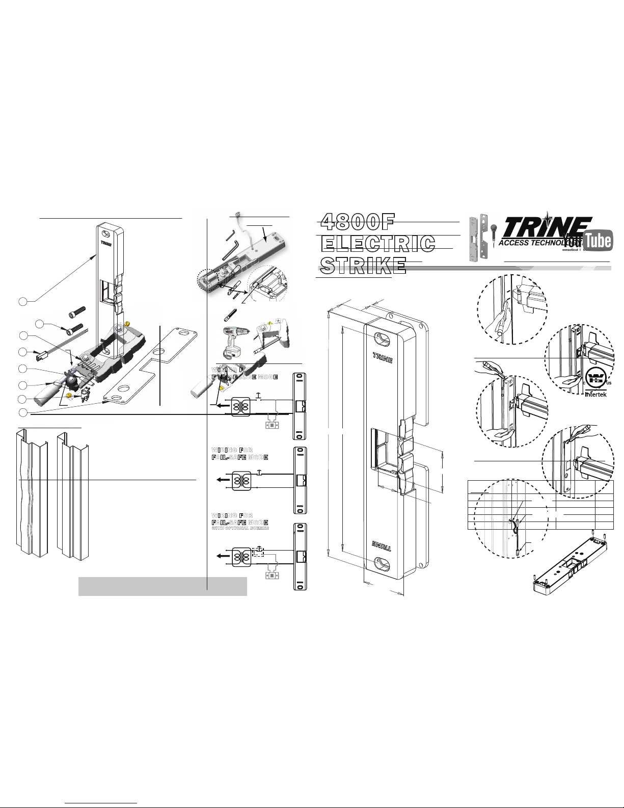
TRINE 4800F
THE FIRE RATED SOLUTION
FOR RIM PANIC EXIT DEVICES
4800F ELECTRICAL CHARACTERISTICS:
4800F
ELECTRIC
STRIKE
INSTALLATION INSTRUCTIONS Congratulations on the purchase of this quality TRINE
security product. This product has been designed to
install easily, perform reliably, and provide years of trouble
free security.
BEFORE PROCEEDING
with your installation, please review the
following list of features. If you have any questions after reading
this document please call TRINE's TECHNICAL SUPPORT
(203) 730-1756, or visit us online @ trineonline.com
Built-in Electronics: The 4800F automaticallys allows
12-24AC & DC power, plus surge and kickback protection.
There are no external ‘pacs’ to use or install.
The 4800F is WH recognized for:
Class A, 3 Hour Single door / frame configuration
- UL10C, Fire Tests of Door Assemblies
- UBC 7-2, Uniform building Code
- CAN4 S104,
Standard Method for Fire Tests of Door
Assemblies
NFPA 252
Issue: 1999/01/01 Standard Methods of Fire Tests of Door
Assemblies
NOTE: WH fire listing is void when using fail safe action.
BHMA Grade 1 Electric Strike
9"
1 3/4"
8 1/4"
1 1/2"
1/8"
3/4"
7/8"
Pull-in/Hold
Amps (A) Duty
Voltage Sound
12DC .566 A/.217 A Intm/Cont. Silent
24DC .253 A/.099 A Intm/Cont. Silent
12AC
@ 50-60Hz
.509 A/.181 A Intm/Cont. Silent
16AC
@ 50-60Hz
.405 A/.149 A Intm/Cont. Silent
24AC
@ 50-60Hz
.215 A/.087 A Intm/Cont. Silent
OPERATING TEMP RANGE: -20°C TO +65°C
DO NOT APPLY AN OVER VOLTAGE OF MORE THAN 10%
OVER THE RATED
OPERATING VOLTAGE OF THE
STRIKE OR THE SOLENOID WILL BE DAMAGED.
2 Parklawn Drive l Suite F l Bethel l Connecticut l 06801
TO 120V
AC LINE
USE 12V THRU 24V
AC OR DC
TRANSFORMER
WIRINGFOR
FAIL-SECURE MODE
SWITCH
NORMALLY
OPEN
FAIL-SECURE
CONFIGURED
STRIKE
OPTIONAL BUZZER
NOTE: MATCH THE VOLTAGE
OF THE TRANSFORMER
AND IF REQUIRED,
OBSERVE POLARITY
USE 12V THRU 24V
AC OR DC
TRANSFORMER
TO 120V
AC LINE
WIRINGFOR
FAIL-SAFE MODE
SWITCH
NORMALLY
CLOSED
FAIL-SAFE
CONFIGURED
STRIKE
USE 12V THRU 24V
AC OR DC
TRANSFORMER
TO 120V
AC LINE
WIRINGFOR
FAIL-SAFE MODE
WITH OPTIONAL BUZZER
SWITCH
SINGLE POLE
DOUBLE THROW
FAIL-SAFE
CONFIGURED
STRIKE
OPTIONAL BUZZER
NOTE: MATCH THE VOLTAGE
OF THE TRANSFORMER
AND IF REQUIRED,
OBSERVE POLARITY
RECOMMENDED PREINSTALLATION CHECK FOR THE 4800F SURFACE
MOUNT STRIKE:
1. Determine that door is properly adjusted; Door must operate properly in order for
system to provide best results.
2. Door must swing properly, without interfering with jamb or sill
3. The door should be equipped with a door closer and the door closer "latch
mode" must hold door in a completely closed position in order to avoid the lock
latch from applying pressure against the releasing latch portion of the electric
strike.
4. Electrical wire connections must be completed and ready to be terminated
inside the frame.
5. Confirm that the power line in the frame is the correct voltage, amperage, and
that the switch works properly.
6. Confirm proper clearance exists between the end of the lock latch and jamb.
7. The electric door strike must be aligned properly with lock latch when it is
installed on the doorjamb.
8. For best installation results, the door frame must be reasonably flat and straight.
2. 3.
WHAT IS INCLUDED IN THE 4800F BOX:
INCLUDED IN THE BOX ARE:
1 - (1) 4800 OR 4801 SURFACE MOUNTED STRIKE
2 - (2) 1/4-20 x 1" UH CAP SOCKET MOUNTING SCREWS
3 - (4) ANCHOR SYSTEM PINS
4 - (1) QUICK CONNECT SOCKET AND WIRE ASSEMBLY
5 - (2) SEALED CRIMP CONNECTORS
6 - (1) FAIL SAFE SPRING (RED COLORED) & SOLENOID PLUNGER
7 - (1) FAIL SAFE CAM (NOTE: NOT FIRE RATED WHEN CONFIGURED FAIL-SAFE)
8 - (1) 1/8" THICK SPACER PLATE/ FRAME MOUNTING TEMPLATE
1
7
3
8
4
2
5
6
RECOMMENDED
TOOLS:
- 3/32 inch Allen Wrench
- 3/16 inch Allen Wrench
- 3/4 inch diameter Drill Bit
- #7 (0.201 inch
diameter) Drill Bit
- #30 (0.128 inch
diameter) Drill Bit
(for the optional Anchor Pins)
- 1/4-20 Tap
- Drill
- Marker
Figure 3
Figure 6
Figure 1
With the door closed,
mark the position of
the bolt on the frame.
Figure 2
Position the 4800F on
the frame and mark
the desire position.
Figure 4
Use the spacer as
template to mark the
holes you desire to use.
Push the anchor pins in
the back of any 4800F
series strike if you
desire to use this
Figure 5
Crimp the quick
connect socket
assembly to the
power wires.
Crimp Connectors
Quick Connect
Socket Assembly
Power Wire
1. Mark the end position of the exit devices latchbolt on the doorframe.
(Take off the original strike if present). See Figure 1.
2. Using the marks you just made as your guide, position the 4800F
over the mark on the frame. Make sure that the Auxiliary latch rides
up properly over the 4800's edge, and is engaged, and that the door
is in the fully closed position. See Figure 2
3. When you are confident with the position of the 4800F, mark two
perpendicular edges of the 4800F on the frame See Figure 3
4. Put the 4800F aside for a moment and place the spacer supplied
with the 4800F inside the marks you just made on the frame.
5. Using the spacer as a template; mark the two mounting holes and
the wire exit hole. If you are using the optional anchor pins, mark the
anchor pin positions using the spacer as a template. See Figure 4
6. Using a #7 bit, drill the two mounting holes and tap them ¼-20.
7. Using a ¾ inch diameter bit, drill the power wire exit hole
8. If you are utilizing the anchor pin system, use a #30 bit, drill the four
anchor pin holes.
9. Deburr any sharp edges around the holes after drilling, so that the
4800F will rest on a smooth clean surface and the wires will not be
accidentally cut or damaged while installing.
10. Pull the power wiring down the door frame and through the ¾ inch
diameter power wire hole.
11. Using the provided sealed crimp connectors, terminate the quick
connect socket assembly to the power wires. See Figure 5 (NOTE:
The 4800F is not polarized)
12.
If you intend to use the anchor pins system, insert them into the four
holes on the back side of the 4800F. See Figure 6. If you also intend to
use the 1/8" thick spacer plate, you can now slip the plate over the pins.
13. Snap together the power supply side connector coming off the
frame to the 4800 connector. Carefully push the wires and
connectors back into the frame.
14. Using the 2 mounting screws, mount the 4800F strike to the frame.
15. Adjust the strike to the desired position and tighten the mounting
screws using the 3/16 inch Allen wrench.
16. Using the 3/32 inch Allen wrench turn the two setscrews on the side
of the 4800F until they support the strike. DO NOT over tighten the
setscrews.
17. Turn the power ON and test your installation. Installation is now
complete.
INSTALLATION PROCEDURE:
CAUTION: TO AVOID ELECTRICAL SHOCK AND INJURIES,
BEFORE DOING YOUR WIRING, TURN OFF THE POWER FROM
THE CIRCUIT BREAKER.
CHECK OUT THE VIDEO ON
SEARCH
“4850ITL”
USE THE 4850ITL TO QUICKLY
MARK, TEST, ADJUST, CENTER
PUNCH AND SKIP MOST OF
THESE STEPS! more info @ trineonline.com/4850itl.php

Fail Safe
(Fire Rating is void
when 4800F is fail-safe)
You should NOT see the "X" on top of the actuator cam.
Use the plunger and
RED colored solenoid
spring assembly.
Fail Secure
You should have the "X" mark on top of the actuator cam.
Use the plunger and
BLUE colored solenoid
spring assembly.
DO NOT OPEN
THIS SIDE.
TROUBLESHOOTING THE COMPLETED INSTALLATION:
.
Seat wires properly in
the housing channel so
the cover will seat flat.
INSTRUCTIONS FOR CHANGING THE THE 4800F FROM FAIL SECURE
TO FAIL SAFE:
To change the Fail Secure 4800F into a Fail Safe , open the
mechanism side of the strike (as shown on the right) by removing
the mechanism cover screws (3 places) and the cover. Lift the solenoid
and gently pull off the solenoid plunger and BLUE spring assembly
and replace it with the solenoid plunger and RED colored spring
assembly. Pull off the actuator cam, and replace it with the fail-safe cam.
Before closing the unit, make sure that the wires are properly seated
on the wire channel (see figure on right). Save the plunger and BLUE
colored spring assembly for future use.
For changing from Fail Safe to Fail Secure, just reverse the
above procedure
SYMPTOM: ELECTRIC RELEASE IS NOT ACTUATING:
1. Verify proper voltage is present AT STRIKE. If voltage is present: the strike may have been
affected during the installation, or dirt or debris may be preventing proper operation. Inspect
electric release and clean. NOTE: DO NOT LUBRICATE SOLENOID
2. If voltage IS NOT present:
A) Verify Circuit breaker is on, B) Verify voltage at the transformer/power supply output. C)
Verify that there are no additional, external switches or devices which may be interrupting your
circuit. D) Check for damaged wiring or bad wire splices.
SYMPTOM: STRIKE IS WORKING BUT WILL NOT OPEN:
1. Check for other locks on door
2. Check for proper lock-latch engagement
3. Check for excessive back pressure on door release latch by following these steps:
A) Push the door from the outside to try and relieve the bolt to latch pressure and actuate
the 4800F. B) While the 4800F is unlatched swing the door open. If the door opens, then the bolt
maybe applying pressure to the latch. Adjust the position of the 4800F to relieve the pressure.
POSSIBLE REMEDIES:
1. Re-adjust (or install) a door closer, Remove door silencers, Re-center electric release in jamb,
Remove or trim weather stripping around the door.
2. Installing this strike on an uneven surface can cause problems with the internal mechanism of
this device. Specifically, it will cause localized mechanical pinching of the moving parts. Locate
where the pinching is occurring and level the frame surface at that location. (FIG W)
4.
Uneven
Frame Soffit
Ideal Frame
Soffit Flatness
(FIG W)
PHONE: (203) 730-1756
FAX: (203) 730-1781
2 Parklawn Dr., Suite F
Bethel, CT 06801
email: customerservice@trineonline.com
website: www.trineonline.com
V. 16.0226
TRINE 4800F
THE FIRE RATED SOLUTION
FOR RIM PANIC EXIT DEVICES
4800F ELECTRICAL CHARACTERISTICS:
4800F
ELECTRIC
STRIKE
INSTALLATION INSTRUCTIONS Congratulations on the purchase of this quality TRINE
security product. This product has been designed to
install easily, perform reliably, and provide years of trouble
free security.
BEFORE PROCEEDING
with your installation, please review the
following list of features. If you have any questions after reading
this document please call TRINE's TECHNICAL SUPPORT
(203) 730-1756, or visit us online @ trineonline.com
Built-in Electronics: The 4800F automaticallys allows
12-24AC & DC power, plus surge and kickback protection.
There are no external ‘pacs’ to use or install.
The 4800F is WH recognized for:
Class A, 3 Hour Single door / frame configuration
- UL10C, Fire Tests of Door Assemblies
- UBC 7-2, Uniform building Code
- CAN4 S104,
Standard Method for Fire Tests of Door
Assemblies
NFPA 252
Issue: 1999/01/01 Standard Methods of Fire Tests of Door
Assemblies
NOTE: WH fire listing is void when using fail safe action.
BHMA Grade 1 Electric Strike
9"
1 3/4"
8 1/4"
1 1/2"
1/8"
3/4"
7/8"
Pull-in/Hold
Amps (A) Duty
Voltage Sound
12DC .566 A/.217 A Intm/Cont. Silent
24DC .253 A/.099 A Intm/Cont. Silent
12AC
@ 50-60Hz
.509 A/.181 A Intm/Cont. Silent
16AC
@ 50-60Hz
.405 A/.149 A Intm/Cont. Silent
24AC
@ 50-60Hz
.215 A/.087 A Intm/Cont. Silent
OPERATING TEMP RANGE: -20°C TO +65°C
DO NOT APPLY AN OVER VOLTAGE OF MORE THAN 10%
OVER THE RATED
OPERATING VOLTAGE OF THE
STRIKE OR THE SOLENOID WILL BE DAMAGED.
2 Parklawn Drive l Suite F l Bethel l Connecticut l 06801
TO 120V
AC LINE
USE 12V THRU 24V
AC OR DC
TRANSFORMER
WIRINGFOR
FAIL-SECURE MODE
SWITCH
NORMALLY
OPEN
FAIL-SECURE
CONFIGURED
STRIKE
OPTIONAL BUZZER
NOTE: MATCH THE VOLTAGE
OF THE TRANSFORMER
AND IF REQUIRED,
OBSERVE POLARITY
USE 12V THRU 24V
AC OR DC
TRANSFORMER
TO 120V
AC LINE
WIRINGFOR
FAIL-SAFE MODE
SWITCH
NORMALLY
CLOSED
FAIL-SAFE
CONFIGURED
STRIKE
USE 12V THRU 24V
AC OR DC
TRANSFORMER
TO 120V
AC LINE
WIRINGFOR
FAIL-SAFE MODE
WITH OPTIONAL BUZZER
SWITCH
SINGLE POLE
DOUBLE THROW
FAIL-SAFE
CONFIGURED
STRIKE
OPTIONAL BUZZER
NOTE: MATCH THE VOLTAGE
OF THE TRANSFORMER
AND IF REQUIRED,
OBSERVE POLARITY
RECOMMENDED PREINSTALLATION CHECK FOR THE 4800F SURFACE
MOUNT STRIKE:
1. Determine that door is properly adjusted; Door must operate properly in order for
system to provide best results.
2. Door must swing properly, without interfering with jamb or sill
3. The door should be equipped with a door closer and the door closer "latch
mode" must hold door in a completely closed position in order to avoid the lock
latch from applying pressure against the releasing latch portion of the electric
strike.
4. Electrical wire connections must be completed and ready to be terminated
inside the frame.
5. Confirm that the power line in the frame is the correct voltage, amperage, and
that the switch works properly.
6. Confirm proper clearance exists between the end of the lock latch and jamb.
7. The electric door strike must be aligned properly with lock latch when it is
installed on the doorjamb.
8. For best installation results, the door frame must be reasonably flat and straight.
2. 3.
WHAT IS INCLUDED IN THE 4800F BOX:
INCLUDED IN THE BOX ARE:
1 - (1) 4800 OR 4801 SURFACE MOUNTED STRIKE
2 - (2) 1/4-20 x 1" UH CAP SOCKET MOUNTING SCREWS
3 - (4) ANCHOR SYSTEM PINS
4 - (1) QUICK CONNECT SOCKET AND WIRE ASSEMBLY
5 - (2) SEALED CRIMP CONNECTORS
6 - (1) FAIL SAFE SPRING (RED COLORED) & SOLENOID PLUNGER
7 - (1) FAIL SAFE CAM (NOTE: NOT FIRE RATED WHEN CONFIGURED FAIL-SAFE)
8 - (1) 1/8" THICK SPACER PLATE/ FRAME MOUNTING TEMPLATE
1
7
3
8
4
2
5
6
RECOMMENDED
TOOLS:
- 3/32 inch Allen Wrench
- 3/16 inch Allen Wrench
- 3/4 inch diameter Drill Bit
- #7 (0.201 inch
diameter) Drill Bit
- #30 (0.128 inch
diameter) Drill Bit
(for the optional Anchor Pins)
- 1/4-20 Tap
- Drill
- Marker
Figure 3
Figure 6
Figure 1
With the door closed,
mark the position of
the bolt on the frame.
Figure 2
Position the 4800F on
the frame and mark
the desire position.
Figure 4
Use the spacer as
template to mark the
holes you desire to use.
Push the anchor pins in
the back of any 4800F
series strike if you
desire to use this
Figure 5
Crimp the quick
connect socket
assembly to the
power wires.
Crimp Connectors
Quick Connect
Socket Assembly
Power Wire
1. Mark the end position of the exit devices latchbolt on the doorframe.
(Take off the original strike if present). See Figure 1.
2. Using the marks you just made as your guide, position the 4800F
over the mark on the frame. Make sure that the Auxiliary latch rides
up properly over the 4800's edge, and is engaged, and that the door
is in the fully closed position. See Figure 2
3. When you are confident with the position of the 4800F, mark two
perpendicular edges of the 4800F on the frame See Figure 3
4. Put the 4800F aside for a moment and place the spacer supplied
with the 4800F inside the marks you just made on the frame.
5. Using the spacer as a template; mark the two mounting holes and
the wire exit hole. If you are using the optional anchor pins, mark the
anchor pin positions using the spacer as a template. See Figure 4
6. Using a #7 bit, drill the two mounting holes and tap them ¼-20.
7. Using a ¾ inch diameter bit, drill the power wire exit hole
8. If you are utilizing the anchor pin system, use a #30 bit, drill the four
anchor pin holes.
9. Deburr any sharp edges around the holes after drilling, so that the
4800F will rest on a smooth clean surface and the wires will not be
accidentally cut or damaged while installing.
10. Pull the power wiring down the door frame and through the ¾ inch
diameter power wire hole.
11. Using the provided sealed crimp connectors, terminate the quick
connect socket assembly to the power wires. See Figure 5 (NOTE:
The 4800F is not polarized)
12.
If you intend to use the anchor pins system, insert them into the four
holes on the back side of the 4800F. See Figure 6. If you also intend to
use the 1/8" thick spacer plate, you can now slip the plate over the pins.
13. Snap together the power supply side connector coming off the
frame to the 4800 connector. Carefully push the wires and
connectors back into the frame.
14. Using the 2 mounting screws, mount the 4800F strike to the frame.
15. Adjust the strike to the desired position and tighten the mounting
screws using the 3/16 inch Allen wrench.
16. Using the 3/32 inch Allen wrench turn the two setscrews on the side
of the 4800F until they support the strike. DO NOT over tighten the
setscrews.
17. Turn the power ON and test your installation. Installation is now
complete.
INSTALLATION PROCEDURE:
CAUTION: TO AVOID ELECTRICAL SHOCK AND INJURIES,
BEFORE DOING YOUR WIRING, TURN OFF THE POWER FROM
THE CIRCUIT BREAKER.
CHECK OUT THE VIDEO ON
SEARCH
“4850ITL”
USE THE 4850ITL TO QUICKLY
MARK, TEST, ADJUST, CENTER
PUNCH AND SKIP MOST OF
THESE STEPS! more info @ trineonline.com/4850itl.php

You should NOT see the "X" on top of the actuator cam.
Use the plunger and
RED colored solenoid
spring assembly.
Fail Secure
You should have the "X" mark on top of the actuator cam.
Use the plunger and
BLUE colored solenoid
spring assembly.
DO NOT OPEN
THIS SIDE.
TROUBLESHOOTING THE COMPLETED INSTALLATION:
.
Seat wires properly in
the housing channel so
the cover will seat flat.
INSTRUCTIONS FOR CHANGING THE THE 4850 FROM FAIL SECURE
TO FAIL SAFE:
To change the Fail Secure 4850 into a Fail Safe, open the
mechanism side of the strike (as shown on the right) by removing
the mechanism cover screws (3 places) and the cover. Lift the solenoid
and gently pull off the solenoid plunger and BLUE spring assembly
and replace it with the solenoid plunger and RED colored spring
assembly. Pull off the actuator cam, and replace it with the fail-safe cam.
Before closing the unit, make sure that the wires are properly seated
on the wire channel (see figure on right). Save the plunger and BLUE
colored spring assembly for future use.
For changing from Fail Safe to Fail Secure, just reverse the
above procedure
4850 THICKNESSES:
Combining the 1/8” spacer and 1/4” spacer the 4850’s open
cavity allows for multiple thicknesses: 1/2”, 5/8“, 3/4” and 7/8”
SYMPTOM: ELECTRIC RELEASE IS NOT ACTUATING:
1. Verify proper voltage is present AT STRIKE. If voltage is present: the strike may have been
affected during the installation, or dirt or debris may be preventing proper operation. Inspect
electric release and clean. NOTE: DO NOT LUBRICATE SOLENOID
2. If voltage IS NOT present:
A) Verify Circuit breaker is on, B) Verify voltage at the transformer/power supply output. C)
Verify that there are no additional, external switches or devices which may be interrupting your
circuit. D) Check for damaged wiring or bad wire splices.
SYMPTOM: STRIKE IS WORKING BUT WILL NOT OPEN:
1. Check for other locks on door
2. Check for proper lock-latch engagement
3. Check for excessive back pressure on door release latch by following these steps:
A) Push the door from the outside to try and relieve the bolt to latch pressure and actuate
the 4800F. B) While the 4850 is unlatched swing the door open. If the door opens, then the bolt
maybe applying pressure to the latch. Adjust the position of the 4850 to relieve the pressure.
POSSIBLE REMEDIES:
1. Re-adjust (or install) a door closer, Remove door silencers, Re-center electric release in jamb,
Remove or trim weather stripping around the door.
2. Installing this strike on an uneven surface can cause problems with the internal mechanism of
this device. Specifically, it will cause localized mechanical pinching of the moving parts. Locate
where the pinching is occurring and level the frame surface at that location. (FIG W)
4. 1.
PHONE: (203) 730-1756
FAX: (203) 730-1781
2 Parklawn Dr., Suite F
Bethel, CT 06801
email: customerservice@trineonline.com
website: www.trineonline.com
V. 17.0407
Uneven
Frame Soffit
Ideal Frame
Soffit Flatness
(FIG W)
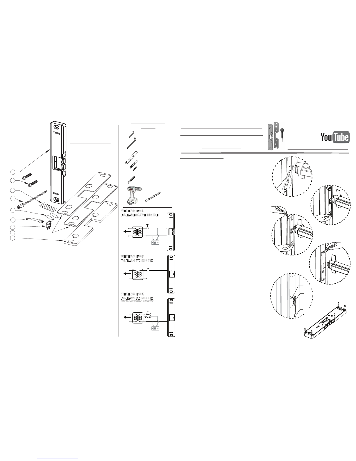
TRINE 4850 - 1/2” THICK ELECTRIC
THE ONE BOX SOLUTION
FOR RIM PANIC EXIT DEVICES
4850 ELECTRICAL CHARACTERISTICS:
4850
ELECTRIC
STRIKE
4850PoE/4850LCD
INSTALLATION INSTRUCTIONS Congratulations on the purchase of this quality TRINE
security product. This product has been designed to
install easily, perform reliably, and provide years of trouble
free security.
BEFORE PROCEEDING
with your installation, please review the
following list of features. If you have any questions after reading
this document please call TRINE's TECHNICAL SUPPORT
(203) 730-1756 , or visit us online @ trineonline.com
Built-in Electronics: The 4850 automatically allows 12-24DC
power, plus surge and kickback protection. There are no
external ‘pacs’ to use or install.
BHMA Grade 1 Electric Strike
- 1,000,000+ Life Cycles
- 1,500+ lbs Holding Force
Single Locking Mechanism
Pull-in/Hold
Amps (A) Duty
Voltage Sound
Sound
12DC .500 A/.178 A Intm/Cont. Silent
16DC .385 A/.131 A Intm/Cont. Silent
24DC .255 A/.084 A Intm/Cont. Silent
4850PoE ELECTRICAL CHARACTERISTICS:
Amps (A) DutyVoltage
12DC .260 A Intm/Cont. Silent
OPERATING TEMP RANGE: -20°C TO +65°C
2 Parklawn Drive l Suite F l Bethel l Connecticut l 06801
Sound
4850LCD ELECTRICAL CHARACTERISTICS:
Amps (A) DutyVoltage
24DC .135 A Intm/Cont. Silent
1/2”
DO NOT APPLY AN OVER VOLTAGE OF MORE THAN 10% OVER
THE RATED
OPERATING VOLTAGE OF THE STRIKE OR THE SOLENOID
WILL BE DAMAGED.
DO NOT APPLY AC POWER OR THE SOLENOID WILL BE DAMAGED.
1/16"
1/16"
9"
1 1/2"
1/4"
8 1/4"
1 3/4"
1 1/8"
TO 120V
AC LINE
USE 12V THRU 24V
DC TRANSFORMER
(Match voltage with
4850PoE and 4850LCD)
(Match voltage with
4850PoE and 4850LCD)
(Match voltage with
4850PoE and 4850LCD)
WIRINGFOR
FAIL-SECURE MODE
SWITCH
NORMALLY
OPEN
FAIL-SECURE
CONFIGURED
STRIKE
OPTIONAL BUZZER
NOTE: MATCH THE VOLTAGE
OF THE TRANSFORMER
AND IF REQUIRED,
OBSERVE POLARITY
USE 12V THRU 24V
DC TRANSFORMER
TO 120V
AC LINE
WIRINGFOR
FAIL-SAFE MODE
SWITCH
NORMALLY
CLOSED
FAIL-SAFE
CONFIGURED
STRIKE
USE 12V THRU 24V
DC TRANSFORMER
TO 120V
AC LINE
WIRINGFOR
FAIL-SAFE MODE
WITH OPTIONAL BUZZER
SWITCH
SINGLE POLE
DOUBLE THROW
FAIL-SAFE
CONFIGURED
STRIKE
OPTIONAL BUZZER
NOTE: MATCH THE VOLTAGE
OF THE TRANSFORMER
AND IF REQUIRED,
OBSERVE POLARITY
RECOMMENDED PREINSTALLATION CHECK FOR THE 4850 SURFACE
MOUNT STRIKE:
1. Determine that door is properly adjusted; Door must operate properly in order for
system to provide best results.
2. Door must swing properly, without interfering with jamb or sill
3. The door should be equipped with a door closer and the door closer "latch mode"
must hold door in a completely closed position in order to avoid the lock latch from
applying pressure against the releasing latch portion of the electric strike
.
4. Electrical wire connections must be completed and ready to be terminated
inside the frame.
5. Confirm that the power line in the frame is the correct voltage, amperage, and
that the switch works properly.
6. Confirm proper clearance exists between the end of the lock latch and jamb.
7. The electric door strike must be aligned properly with lock latch when it is
installed on the doorjamb.
8. For best installation results, the door frame must be reasonably flat and straight.
2. 3.
WHAT IS INCLUDED
IN THE 4850 BOX:
INCLUDED IN THE BOX ARE:
1 - (1) 4850 (OR 4850PoE/4850LCD) SURFACE MOUNTED STRIKE
2 - (2) 1/4-20 x 1" UH CAP SOCKET MOUNTING SCREWS
3 - (6) ANCHOR SYSTEM PINS
4 - (1) QUICK CONNECT SOCKET AND WIRE ASSEMBLY
5 - (2) SEALED CRIMP CONNECTORS
6 - (1) FAIL SAFE SPRING (RED COLORED) & SOLENOID PLUNGER
7 - (1) FAIL SAFE CAM
8 - (2) 1/16" THICK SPACER PLATES (replaces single 1/8” plate)
9 - (1) 1/4" THICK SPACER PLATE
1
7
3
8
9
4
2
5
6
RECOMMENDED
TOOLS:
- 3/32 inch Allen Wrench
- 3/16 inch Allen Wrench
- 3/4 inch diameter Drill Bit
- #7 (0.201 inch
diameter) Drill Bit
- #30 (0.128 inch
diameter) Drill Bit
(for the optional Anchor Pins)
- 1/4-20 Tap
- Drill
- Marker
Figure 3
Figure 1
With the door closed,
mark the position of
the bolt on the frame.
Figure 2
Position the 4850 on
the frame and mark
the desire position.
Figure 4
Use the spacer as
template to mark the
holes you desire to use.
Figure 6
Push the anchor pins in
the back of any 4850
series strike if you
desire to use this
Figure 5
Crimp the quick
connect socket
assembly to the
power wires.
Crimp Connectors
Quick Connect
Socket Assembly
Power Wire
1. Mark the end position of the exit devices latchbolt on the doorframe.
(Take off the original strike if present). See Figure 1.
2. Using the marks you just made as your guide, position the 4850 over
the mark on the frame. Make sure that the Auxiliary latch rides up
properly over the 4850's edge, and is engaged, and that the door is
in the fully closed position. See Figure 2
3. When you are confident with the position of the 4850, mark two
perpendicular edges of the 4850 on the frame See Figure 3
4. Put the 4850 aside for a moment and place the spacer supplied with
the 4850 inside the marks you just made on the frame.
5. Using the spacer as a template; mark the two mounting holes and
the wire exit hole. If you are using the optional anchor pins, mark the
anchor pin positions using the spacer as a template. See Figure 4
6. Using a #7 bit, drill the two mounting holes and tap them ¼-20.
7. Using a ¾ inch diameter bit, drill the power wire exit hole
8. If you are utilizing the anchor pin system, use a #30 bit, drill the four
anchor pin holes.
9. Deburr any sharp edges around the holes after drilling, so that the
4850 will rest on a smooth clean surface and the wires will not be
accidentally cut or damaged while installing.
10. Pull the power wiring down the door frame and through the ¾ inch
diameter power wire hole.
11. Using the provided sealed crimp connectors, terminate the quick
connect socket assembly to the power wires. See Figure 5 (NOTE:
The 4850 is not polarized)
12.
If you intend to use the anchor pins system, insert them into the 6 holes
on the back side of the 4850. See Figure 6. If you also intend to use the
1/8" thick spacer plate, you can now slip the plate over the pins.
13. Snap together the power supply side connector coming off the
frame to the 4850 connector. Carefully push the wires and
connectors back into the frame.
14. Using the 2 mounting screws, mount the 4850 strike to the frame.
15. Adjust the strike to the desired position and tighten the mounting
screws using the 3/16 inch Allen wrench.
16. Using the 3/32 inch Allen wrench turn the two setscrews on the side
of the 4850 until they support the strike. DO NOT over tighten the
setscrews.
17. Turn the power ON and test your installation. Installation is now
complete.
INSTALLATION PROCEDURE:
CAUTION: TO AVOID ELECTRICAL SHOCK AND INJURIES,
BEFORE DOING YOUR WIRING, TURN OFF THE POWER FROM
THE CIRCUIT BREAKER.
CHECK OUT THE VIDEO ON
SEARCH
“4850ITL”
USE THE 4850ITL TO QUICKLY
MARK, TEST, ADJUST, CENTER
PUNCH AND SKIP MOST OF
THESE STEPS! more info @ trineonline.com/4850itl.php

APPLICATION:
•Remote central station notification
•Local alarm monitoring
•Triggering video surveillance and
recording systems
•Active relay for trap door systems
•For Indoor applications ONLY.
TECHNICAL SPECIFICATIONS:
•SHARP®Infrared optical sensor
•Normally Open and Normally Closed
contact terminals
•Single pole, double throw, Form "C"
relay, rated at 1 Amp at 24 VAC or
24 VDC.
•Sensor Power - 12 through 30 VDC (ONLY)
FEATURES:
•Non-Mechanical operation
•Sensor is concealed within the unit
•Sensor does not require any adjustment
•Ignores ambient light, detecting radiant
Infrared reflections off the pullman latch
•Increase life and decrease in maintenance
due to electronic versus mechanical
operation
SENSOR WIRE
COLOR CODE
POWER LEADS:
Red - Positive
Black - Negative
RELAY LEADS:
Blue - Common
Yellow - Normally Open (NO)
White - Normally Closed (NC)
INFRARED
SENSOR
WIRING SCHEMATICS FOR TYPICAL APPLICATIONS
PREINSTALLATION CONSIDERATION:
When Mounting the 4800FLB, the pullman latch must be positioned as close
as possible to the vertical center of the latch cavity. Having the latch on
center will ensurethat the sensor will have enough surface to detect.
You can use the 1/8" and 1/4” spacer (included, 1/4” is for 4850LB only) to
move the 4850LB/4800FLB closer to the panic bar.
Spacer Plate
QUIESCENT TRIGGER
VOLTAGE CURRENT DRAW CURRENT DRAW
12VDC 13mA 23mA
24VDC 20mA 35mA
30VDC 22mA 39mA
WHITE - NORMALLY CLOSED (NC)
RED +
BLACK -
BLUE COMMON (COM)
YELLOW - NORMALLY OPEN (NO)
NOTE:
Please observe proper polarity for the LB sensor. The RED wire
terminal must be attached to the POSITIVE side and the BLACK wire
terminal must be attached to the NEGATIVE side.
TO TRANSFORMER
12V THROUGH 30V DC
RELAY TERMINALS
TO USER DEVICE OR
SENSORS.
LB SENSOR WIRE TERMINAL
COLOR CODING ASSIGNMENTS
RELAY
COMMON
NC
NO
TRANSFORMER
POWER
BUZZER OR
BELL
RELAY
COMMON
NC
NO
SECURITY SENSOR
For an alarm system a
Buzzer of Bell can be
wired to the NO terminal
such that when the door
is open the Buzzer or Bell
will sound.
For a security system
setup one side of the
circuit can be connected
to the common and the
other side to the NC
terminal so that when the
door is open, the system
senses the relay switch
as open
INSTRUCTION SHEET
SPECIFICATION AND
P: (203) 730-1756 -- F: (203) 730-1781
www.trineonline.com
4850LB/4800FLB
WHITE - NORMALLY CLOSED (NC)
BLACK -
RED +
BLUE COMMON (COM)
YELLOW - NORMALLY OPEN (NO)
120
VAC
12VDC
OUTPUT
CONTROL SWITCH
OR RELAY
PANEL INDICATOR
OR OTHER
SIGNALING DEVICE
POWER
SUPPLY
CONTROL
PANEL
PANEL SIDE
WIRING
FRAME SIDE
WIRING
Hook-up to either
Normally Open
or Normally
Closed Terminal
WHITE - NORMALLY CLOSED (NC)
BLACK -
RED +
BLUE COMMON (COM)
YELLOW - NORMALLY OPEN (NO)
120
VAC
120
VAC
12 - 24 VDC
OUTPUT
12 - 24 VDC
OUTPUT
CONTROL SWITCH
OR RELAY
PANEL INDICATOR
OR OTHER
SIGNALING DEVICE
POWER
SUPPLY 1
POWER
SUPPLY 2 CONTROL
PANEL
PANEL SIDE
WIRING
FRAME SIDE
WIRING
Hook-up to either
Normally Open
or Normally
Closed Terminal
WHITE - NORMALLY CLOSED (NC)
BLACK -
RED +
BLUE COMMON (COM)
YELLOW - NORMALLY OPEN (NO)
120
VAC
120
VAC
120
VAC
12 - 24 VDC
OUTPUT
12 - 24 VDC
OUTPUT
CONTROL SWITCH
OR RELAY
PANEL INDICATOR
OR OTHER
SIGNALING DEVICE
POWER
SUPPLY 1
POWER
SUPPLY 2
POWER
SUPPLY 3
CONTROL
PANEL
PANEL SIDE
WIRING
FRAME SIDE
WIRING
Hook-up to either
Normally Open
or Normally
Closed Terminal
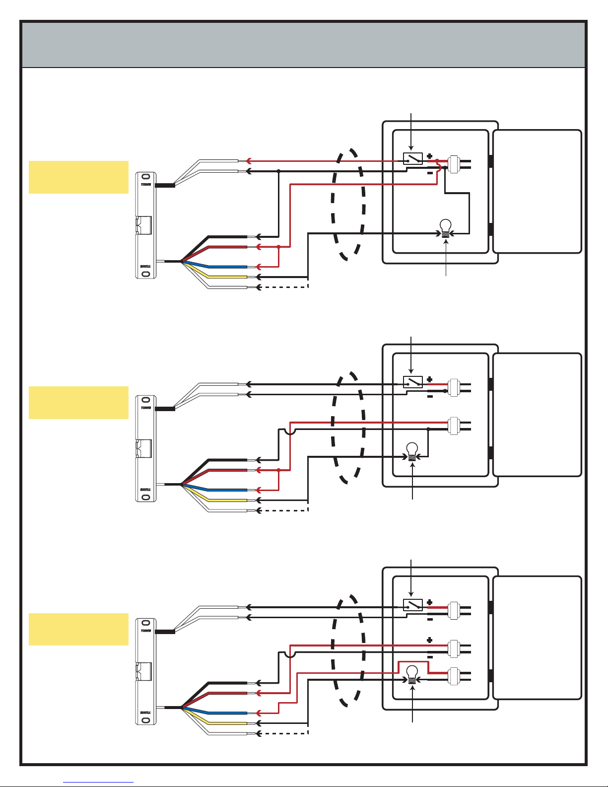
WIRING SCHEMATICS FOR DIFFERENT APPLICATIONS
FOUR WIRE
SCHEMATIC UTILIZING
ONE TRANSFORMER
This wiring arrangement
uses the least amount of
conductors between the
Panel and the Frame.
FIVE WIRE SCHEMATIC
UTILIZING TWO
TRANSFORMERS
If the Signaling Device or
Panel Indicator requires a
different voltage, this
wiring scheme can be
used.
SIX WIRE SCHEMATIC
UTILIZING THREE
TRANSFORMERS
This wiring arrangement
is used to isolate the
strike operation, from the
LB sensor power board
and finally the Panel
Indicator or Signaling
Device.
STRIKE POWER
WIRE LEADS
LB SENSOR POWER
WIRE LEADS
LB SENSOR SIGNAL
WIRE LEADS
STRIKE POWER
WIRE LEADS
LB SENSOR POWER
WIRE LEADS
LB SENSOR SIGNAL
WIRE LEADS
STRIKE POWER
WIRE LEADS
LB SENSOR POWER
WIRE LEADS
LB SENSOR SIGNAL
WIRE LEADS

Model Number:
3478 - Fail Secure
3478RS - Fail Safe
Model Number:
3234W - Fail Secure
3234WRS - Fail Safe
Model Number:
3234 - Fail Secure
3234RS - Fail Safe
1440 Ferris Place · Bronx · New York· 10461-3699
TRINE 3000 SERIES ELECTRIC RELEASES
Congratulations on the purchase of this quality TRINE
security product.
This product has been designed to install easily, perform
reliably, and provide years of trouble free security.
In order for this product to fulfill its objectives, certain
steps must be performed by the installer, and certain site
conditions must be satisfied.
Before proceeding with your installation, please review
the following list of items. If you have any questions first
please finish reading this document to see if the
information you require is contained in this document,
otherwise please call:
TRINE TECH SUPPORT (718) 829-2332 EXT. 425,
or visit the TRINE Website www.TrineOnline.com.
The TRINE Model #3234, #3234W & Model #3478 are
designed for new installation or retrofitting into metal,
wood and aluminum door frames. Be sure that you have
ordered the correct TRINE strike for your application.
FINISHES
3234 3234W 3478
US3 (Polished Brass)
US4 (Satin Brass)
US10B (Dark Bronze)
US26 (Bright Chrome)
US26D (Satin Chrome)
US32D (Satin Stainless Steel)
STANDARD FEATURES
Face Plate - 3234, 2-3/4" x 1-1/8"
3234W, 3-3/4" x 1-1/4"
3478, 4-7/8" x 1-1/4"
Mortise Type - 1" backset (Smallest in the Industry)
Durability - 500,000 Life Cycles
Holding Force - 1,200 Pounds (Static Force)
- 70 ft-lb (Dynamic Force)
All stainless steel locking parts
Solid Cast Latch - Stainless Steel
Cavity: Width 5/8", Height 1-1/8", Depth 1/2"
Non-handed
Heavy-duty latch spring
Silent Operation
Intermittent Duty with the Standard versions
Intermittent and Continuous Duty with the LC versions
Micro Solenoid assembly
Fail-Secure:(standard action) unlocks with power
Fail-Safe: RS (reverse action) unlocks when power is off
RECOMMENDED INSTALLATION SEQUENCE:
1. Verify strike is proper for the door into which it is to be
installed.
2. Verify that you have all parts required to complete the
installation.
3. Verify that the new electric release operates with the
existing power supply/control circuit (retrofit
applications); or verify that the new power supply/
control circuit operates the new electric release (new
installations).
4. Locate and clearly mark the circuit breaker which
provides ac power to your transformer/ power supply
or that supplies power to the receptacle into which you
will plug your transformer/power supply. This will
enable you to safely cut power during installation, and
permit troubleshooting if required.
5. Verify that the receptacle or circuit providing power to
the electric release is not controlled by a wall switch,
time clock, or other external device.
6. Verify that the circuit/receptacle used for the locking
system is not powering any other equipment.
Remember that interruption of power to your locking
system could prevent access into the protected area,
or jeopardize the security/safety of the site's
occupants.
7. Verify that the door and associated components are in
good working order.
8. Install electric release as per attached guidelines.
9. Wire electric release as per attached guidelines.
10. Perform final test of completed installation.

LEFT HAND
(LH)
LEFT HAND
REVERSE BEVEL
(LRB)
RIGHT HAND
(RH)
RIGHT HAND
REVERSE BEVEL
(RRB)
OUTSIDE
OUTSIDE
DOOR HANDING GUIDE
HANDING OF DOOR IS ALWAYS DETERMINED
FROM THE OUTSIDE.
VOLTAGE DROP GUIDE
Length to Transformer 12V 24V
Up to 50 feet 18 AWG 20 AWG
50 to 150 feet 16 AWG 18 AWG
150 to 300 feet 14 AWG 16 AWG
300 to 600 feet 12 AWG 14 AWG
The TRINE MODEL # 3234, #3234W and #3478:
FAIL-SECURE "INTERMITTENT DUTY" units are designed for
momentary application of voltage for access control purposes,
and cannot be continuously powered without permanent and
irreversible damage to the electric strike's solenoid.
The TRINE MODEL #3234-RS, #3234W-RS and #3478-RS:
FAIL-SAFE "CONTINUOUS DUTY" versions may be used for
applications where the release must remain UNLOCKED for
extended periods. Please contact TRINE for other additional
TRINE electric release solutions for those applications requiring
a continuous duty FAIL-SECURE electric release that may be
powered for extended periods, commonly referred to as
CONTINUOUS DUTY.
The TRINE LC version of MODEL # 3234, 3234W, #3478, #
3234-RS, #3234W-RS and #3478-RS can be used for
"INTERMITTENT DUTY" AND "CONTINUOUS DUTY"
3000 SERIES ELECTRICAL CHARACTERISTICS CHART:
STANDARD MODELS
VOLTAGE CURRENT (AMPS)
COIL
RESISTANCE
(OHMS) DUTY AUDIBLE SOUND WIRE COLOR MODEL
12V DC 0.480 25 Int Silent Blue-Blue STD
24V DC 0.240 100 Int Silent White-White STD
LC & RS MODELS
VOLTAGE
CURRENT (AMPS)
PULL-IN/HOLDING
COIL
RESISTANCE
(OHMS) DUTY AUDIBLE SOUND WIRE COLOR MODEL
12V DC 0.743/0.298 13 Int./Cont. Silent Red-Red LC
12V AC 0.715/0.277 13 Int./Cont. Silent Red-Red LC
24V DC 0.397/0.170 13 Int./Cont. Silent Red-Red LC
24V AC 0.378/0.173 13 Int./Cont. Silent Red-Red
LC
Page 2
LUBRICATION: The TRINE Model #3234, #3234W & #3478
do not require lubrication. Lubricating these units will actually
hamper their performance by attracting dust and debris into the
tight tolerance precision Micro Solenoid assembly.
GETTING STARTED: Before proceeding with your
installation, verify that the door to which the electric release is
being applied is in good working condition.
These items are essential for either new installations or retrofits
Items which should be specifically checked prior to beginning
the installation include:
The hinges (or pivots) are in good condition
If your installation is a retrofit, that the existing latch
lines up perfectly with the existing strike plate.
The door is not rubbing on the saddle or anywhere on
the frame
The door closer is not leaking and is in good condition
and properly adjusted.
The door is not warped or otherwise damaged which
might hamper its operation or otherwise affect your
installation or the final system's performance.
That the door frame member into which the door
release is to be installed is deep enough (1 inch) for the
body of the electric strike, and that the wiring to
operate the electric release can be installed for your
application.
HANDING: The TRINE Model #3234, #3234W and #3478 are
non-handed.
DUTY & VOLTAGES: The TRINE Model #3234, #3234W &
Model #3478 are available as FAIL-SECURE (Normally Locked,
Power to Unlock), INTERMITTENT DUTY and are supplied in
two different operating voltage and the LC VERSION, suitable
for use in a range of voltages from 12V to 24V AC or DC. The
TRINE Model #3234RS, 3234WRS & Model #3478RS are FAIL-
SAFE (Normally Unlocked, Power to Lock), continuous duty and
are supplied with LC module.
LC units will operate on any input voltage from 12V to 24V AC
or DC, and offer both the benefits of reducing inventory by
enabling you to stock one strike. In addition, they offer both
surge suppression and inductive kickback protection.
Please refer to the accompanying VOLTAGE DROP CHART for
recommended wire gauges for various voltages and wire
lengths.
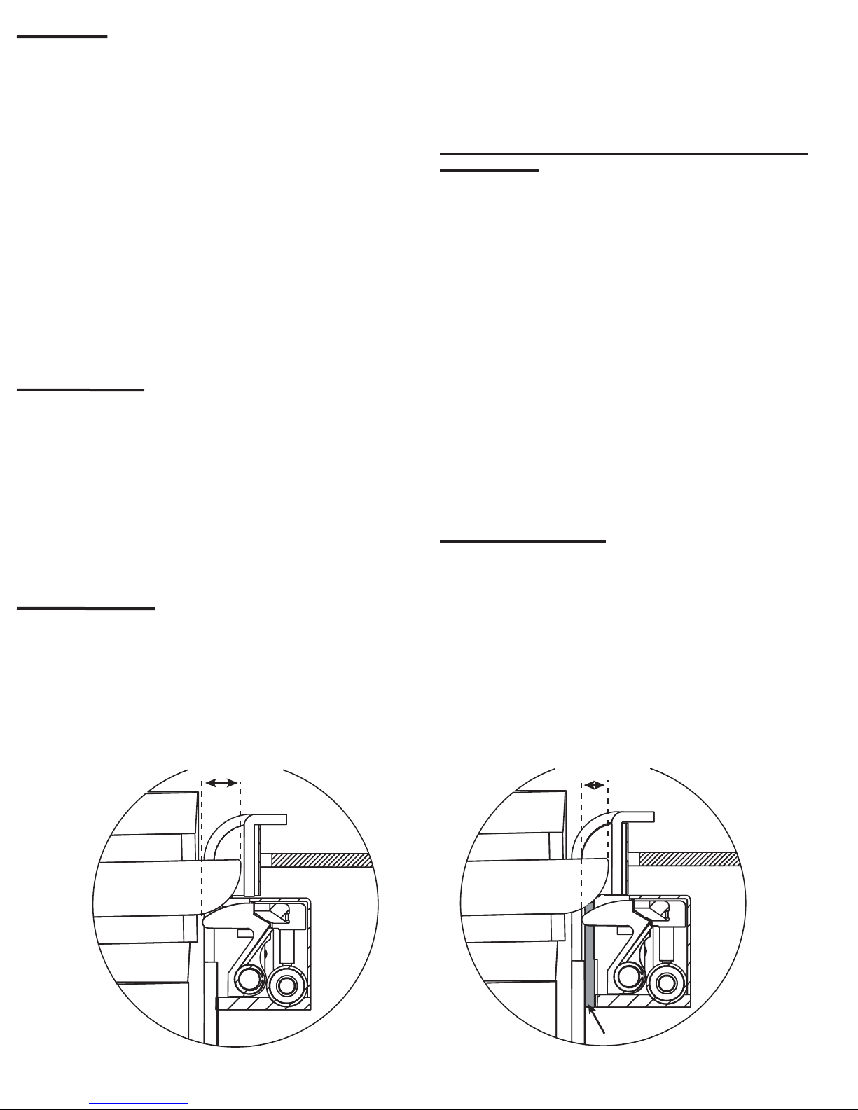
LOCK
LATCH
LOCK
SHIM
LATCH
LOCK - LATCH
ENGAGEMENT
LOCK - LATCH
ENGAGEMENT
FIGURE 4
Page 3
ELECTRICAL: If you are performing a new installation, be
certain that you make provisions for the proper voltage power
supply for your electric strike. If you are performing a retrofit
type installation, determine that the voltage present at the
location of the strike is appropriate for the TRINE strike you
have, that the circuitry supplying the voltage is operating
properly, and also verify that you are able to cut the power
completely to the door location so that you may perform the
installation safely without endangering yourself or causing
damage to the power supply or other devices connected to the
circuit. It is strongly recommended that you also test for high
voltages which may exist between each lead of the power wiring
to the electric release solenoid, and to the door frame which is
an earth ground. Dangerous voltages or currents may occur due
to a miswire or other pre-existing fault conditions in the system
you are servicing.
TESTING YOUR ELECTRIC STRIKE; POWER SUPPLY; &
SWITCHING CIRCUIT PRIOR TO FINAL MOUNTING OF THE
ELECTRIC RELEASE IS RECOMMENDED
POWER SOURCES:
The TRINE MODEL #5208 (12 VDC) or MODEL # 5209 (24
VDC) are suitable DC POWER SUPPLIES which are plug-in
and therefore do not require that the installer perform line
voltage wiring.
TRINE offers several low voltage transformers suitable for use
with the TRINE MODEL #3234, #3234W & #3478 electric
releases.
HARDWIRED POWER SUPPLY MODELS are also available -
see our website or call our Customer Support Line for details.
SILENT OPERATION: The TRINE #3234, #3234W & #3478 are
referred to as "Silent Operating"; unlike some types of AC
electric releases which make a "buzzing sound" when activated.
For some applications, such as entrances into apartment
buildings or storerooms, an audible sound is desirable, and
even expected. For other applications, such as offices, silent
operation is preferred because a buzzing sound is distracting or
disturbing. Verify with your client which they require, and if an
audible signal when the electric release is activated is desirable,
then add a sounding device as shown in the accompanying
wiring diagrams.
CONFIRMING PROPER LOCK-LATCH ENGAGEMENT &
CLEARANCES:
The latch and the lock must engage properly for the electric
strike to operate as intended. On doors where the gap between
the edge of the door and the jamb are within standard tol-
erances and the latch is the proper length, no adjustments will
be required and this is true for the majority of installations.
But too little lock-latch engagement will result in an installation
were the door may be easily spread; allowing the locked door to
be forced open.
Too much lock-latch engagement will result in a situation where
the door release will interfere with the door latch, causing
binding; improper operation and premature mechanical wear on
the latch and release.
Extended latch length (LL) minus the gap (G) between the edge
of the door and the edge of the jamb equals the amount of lock-
latch engagement.
"Lock-Latch Engagement = LL - G"
INSTALLATION OF SHIM:
An adequate amount of clearance must exist between the door
latch and the strike keeper so that they do not interfere or bind
when the door opens or closes. Two 1/16" thick shims are
supplied with the TRINE #3234, #3234W and #3478 which may
be installed as shown in the "Installation Drawings section" to
resolve this situation if this problem is encountered. (also See
Figure 4 below).

INSTALLATION DRAWINGS
WOOD FRAME INSTALLATION
The 3234W's 3-3/4" x 1-1/4" faceplate requires the
least amount of jamb preparation when compared
with other electric strikes.
3/32"
1 1/4"
1 11/16"
1 1/8"
7/16"
1 1/64"
1 1/16"
1 5/16"
3 3/4"
3 3/4"
1 11/16"
1 1/32"
1 1/4"
3 1/8"
1 1/8"
1 5/16"
9/16"
3/32"
5/16"
1"
OPTIONAL
1/16" THICK
SHIM
Page 4
4 7/8"
1 1/4"
1 7/8"
1 1/32"
1 11/16"
1"
3/32"
4 1/8"
3/4"
3 11/32"
5/8"
3/8"
OPTIONAL
1/16" THICK
SHIM
1 1/4"
4 7/8"
3/32"
1 1/16"
1 9/16"
1 1/4"
9/16"
1 3/4"
1 13/16"
1 1/4"
3 3/8"
3/4"
1 1/4"
4 7/8"
1 3/8"
1/8"
3 3/8"
7/16"
METAL AND WOOD FRAME INSTALLATION
The 3478's 4-7/8" x 1-1/4" faceplate
requires the least amount of jamb
preparation when compared
with other electric
strikes.

24V OR 12V AC/DC
TRANSFORMER
LC100
TO 120V AC LINE
FIGURE 2
FAIL-SAFE MODELS
PUSH
BUTTON
NORMALLY
CLOSED
+
-
FAIL-SAFE
ELECTRIC
STRIKE
OPTIONAL
LED
INSTALLATION DRAWINGS (Continued)
1 1/32"
1 11/16"
1"
1 1/8"
5/8"
1 7/16"
5/8"
2 1/8"
1 11/16"
2 3/4"
1/8"
9/16"
5/16"
OPTIONAL
1/16" THICK
SHIM
2 3/4"
1 7/16"
5/8"
1 1/8"
METAL FRAME INSTALLATION
The 3234's 2-3/4" x 1-1/4" faceplate requires the
least amount of jamb preparation when compared
with other electric strikes.
WIRING DIAGRAM
24V DC OR 12V DC
TRANSFORMER
OPTIONAL BUZZER
BZ-12 or BZ-24
TO 120V AC LINE
FIGURE 1
USING DC TRANSFORMER
PUSH
BUTTON
NORMALLY OPEN
** When wiring the optional buzzer, polarity must be
observed. Connect the (+ or RED) positive wire to the
(+) positive side of the circuit and the (- or BLACK)
negative side wire terminal to the negative side of the
circuit.
+
-
+
RED
-
BLACK
FAIL-SECURE
ELECTRIC
STRIKE
Page 5
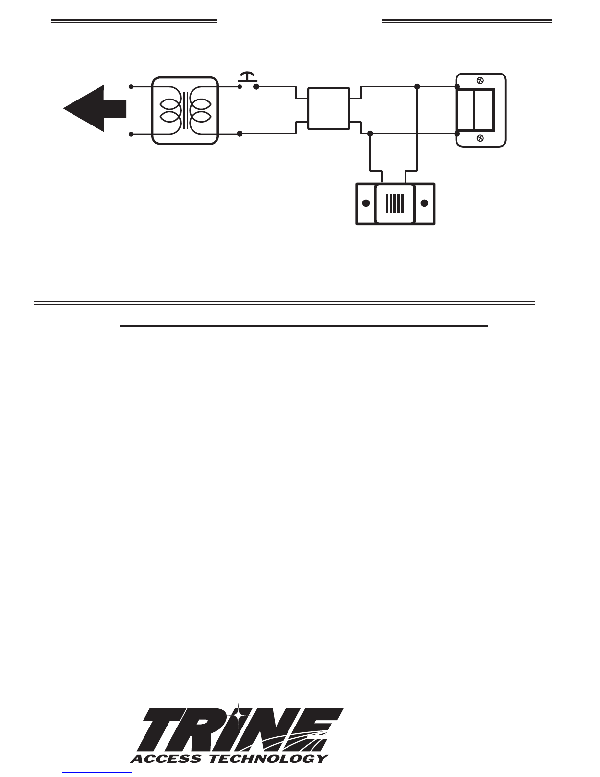
Page 6
24V AC OR 12V AC
TRANSFORMER
OPTIONAL***
BUZZER
BZ-12
BZ-24
BZ-6 - for the LC Version
RECTIFIER*
or
LC100**
TO 120V AC LINE
FIGURE 3
USING AC TRANSFORMER
PUSH
BUTTON
NORMALLY OPEN
* The rectifier can be positioned before of after the push button in
the circuit. The LC module can ONLY be positioned after the push
button as shown above.
** The LC100 module is wired-in like a rectifier and the above
schematic will work also with a DC output transformer.
*** When wiring the optional buzzer, polarity must be observed.
Connect the (+ or RED) positive wire to the (+) positive side of the
circuit and the (- or BLACK) negative side wire terminal to the
negative side of the circuit.
+
-+
RED
-
BLACK
FAIL-SECURE
ELECTRIC
STRIKE
WIRING DIAGRAM (continued)
PHONE: (718) 829-2332 FAX: (718) 829-6405
1440 FERRIS PLACE
BRONX, NY 10461
email: CustomerService@TrineOnline.com
website: www.TrineOnline.com
TROUBLESHOOTING THE COMPLETED INSTALLATION:
SYMPTOM: Electric release is not actuating:
1. Verify proper voltage is present AT STRIKE. If voltage IS present: the strike may have been damaged
during the installation, or dirt or debris may be preventing proper operation.
2. Verify for proper electric release coil resistance (REFER TO COIL ESISTANCE CHART), for either a short
circuit or open circuit. Coil is NOT a serviceable part. Note that intermittent coils can only receive
power for 1 minute or less.
3. If voltage IS NOT present:
Verify Circuit breaker is on
Verify voltage at the transformer/power supply output.
Verify output from rectifier (if used)
Verify that there are no additional, unknown external switches or devices which may be interrupting
your circuit.
Check for damaged wiring or bad wire splices.
SYMPTOM: Door will not open but strike is working
Check for other locks on door
Check for proper lock-latch engagement (SEE SECTION: "CONFIRMING PROPER LOCK-LATCH
ENGAGEMENT & CLEARANCES").
Lock latch engagement may be not set correctly. (If proper clearance cannot be achieved by installing
a shim; a shorter lock latch may be required for your installation.)
Check for excessive backpressure on door release latch by following these steps:
While observing the electric release and latch; apply enough pressure on the door so that the lock's
latch does not press on the electric release's latch. If applying pressure as described does not cause
any movement of the lock away form the latch, then there may be too much pressure on the electric
release's latch. If electric release works properly while you are applying this pressure, then steps must
taken to relieve this pressure. Possible remedies include:
Re-adjust (or install) a door closer
Remove door silencers
Correct excessive door warpage
Re-center electric release in jamb
Remove or trim weather stripping around the door
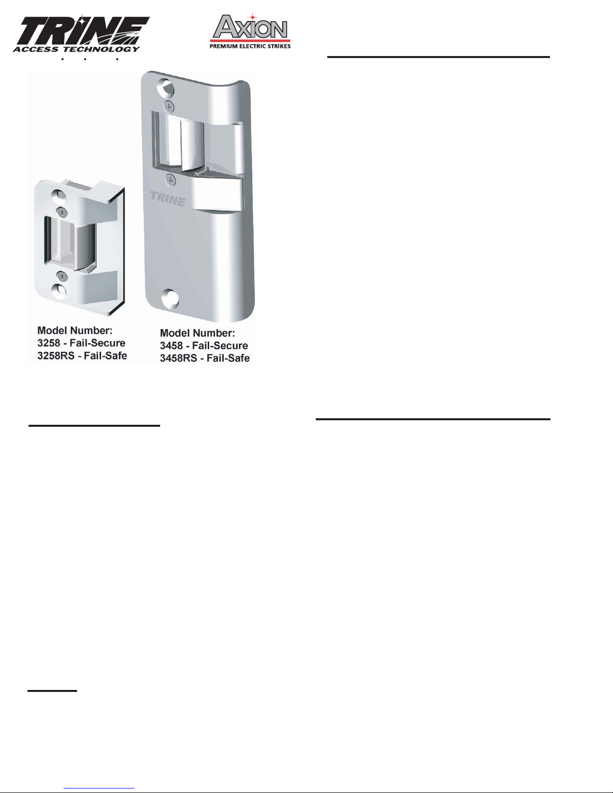
1440 Ferris Place Bronx New York 10461-3699
1
TRINE 3000 SERIES ELECTRIC RELEASES:
Congratulations on the purchase of this quality TRINE
security product.
This product has been designed to install easily,
perform reliably, and provide years of trouble free
security.
In order for this product to fulfill its objectives, certain
steps must be performed by the installer, and certain
site conditions must be satisfied.
Before proceeding with your installation, please review
the following list of items. If you have any questions
first please finish reading this document to see if the
information you require is contained in this document,
otherwise please call TRINE TECH SUPPORT (718) 829-
2332 EXT. 425, or visit the TRINE Website
www.TrineOnline.com.
Both the TRINE Model #3258 & Model #3458 are
designed for new installation or retrofitting into
Aluminum frames. Be sure that you have ordered the
correct TRINE strike for your application.
RECOMMENDED INSTALLATION SEQUENCE:
1. Verify strike is proper for the door into which it is to be
installed.
2. Verify that you have all parts required to complete the
installation.
3. Verify that the new electric release operates with the
existing power supply/control circuit (retrofit
applications); or verify that the new power supply/
control circuit operates the new electric release (new
installations).
4. Locate and clearly mark the circuit breaker which
provides ac power to your transformer/ power supply
or that supplies power to the receptacle into which you
will plug your transformer/power supply. This will
enable you to safely cut power during installation, and
permit troubleshooting if required.
5. Verify that the receptacle or circuit providing power to
the electric release is not controlled by a wall switch,
time clock, or other external device.
6. Verify that the circuit/receptacle used for the locking
system is not powering any other equipment.
Remember that interruption of power to your locking
system could prevent access into the protected area,
or jeopardize the security/safety of the site's
occupants.
7. Verify that the door and associated components are in
good working order.
8. Install electric release as per attached guidelines.
9. Wire electric release as per attached guidelines.
10. Perform final test of completed installation.
Be sure that you have ordered the correct TRINE strike for
your application.
STANDARD FEATURES:
Face Plate - 3258, 2-5/8" x 5/8" - Non-Handed
3458, 4-5/8" x 1-9/16" - Must order LH or RH
All stainless steel locking components
Fail-Secure:(standard action) unlocks with power
applied (MODELS #3258 & #3458)
Fail-Safe: RS (reverse action) unlocks when power is off
(MODELS #3258RS & MODELS #3458RS)
Mortise Type - 1" backset (Smallest in the Industry)
Durability - 500,000 Life Cycles
Holding Force - 1,200 Pounds
Latch Cavity: Width 5/8", Height 1-1/8", Depth 1/2"
Handed - The 3258 is non-handed. The 3458 is handed,
LH for left hand or RH for right hand
Heavy-duty latch spring
Silent Operation
Intermittent Duty
Micro Solenoid assembly
Low current draw
FINISHES:
Satin Stainless Steel - US32D (3458 ONLY)
Satin Chrome - US26D (3258 ONLY)
Dark Bronze - US10B
Bright Chrome - US26
LUBRICATION: The TRINE Model #3258 & Model #3458
do not require lubrication. Lubricating these units will
actually hamper their performance by attracting dust and
debris into the tight tolerance precision Micro Solenoid
assembly
GETTING STARTED: Before proceeding with your
installation, verify that the door to which the electric release
is being applied is in good working condition.
These items are essential for either new installations or
retrofits Items which should be specifically checked prior to
beginning the installation include:
The hinges (or pivots) are in good condition
If your installation is a retrofit, that the existing latch
lines up perfectly with the existing strike plate.
The door is not rubbing on the saddle or anywhere on
the frame
The door closer is not leaking and is in good
condition and properly adjusted.
The door is not warped or otherwise damaged which
might hamper its operation or otherwise affect your
installation or the final system's performance.
That the door frame member into which the door
release is to be installed is deep enough (1 inch) for
the body of the electric strike, and that the wiring to
operate the electric release can be installed for your
application.
FOR RETROFITS:
With only a minimal modification to the frame the Model
#3258 is the ideal replacement for the ADAMS-RITE® #4502
Strike; (Use with Adams-Rite Model 4510, 4710 or 4750 dead
latches)
With only a minimal modification to the frame the Model
#3458 is the ideal replacement for the ADAMS-RITE®
#4730/4501 Strike plate.
For both the TRINE #3258 & #3458 retrofits, these strikes are
designed so that the original mounting tab holes may be
used to secure the electric release into the frame.
Mounting Tabs are supplied with both units for use in new
or retrofit installations.
HANDING: The TRINE Model #3458 is NOT field handable.
Verify that you have ordered the correct handed door
release for your application. The TRINE Model #3258 is
NONE handed.
The TRINE MODEL # 3258 and Model #3458
FAIL-SECURE "INTERMITTENT DUTY" units are designed
for momentary application of less than a minute of
voltage for access control purposes, and cannot be
continuously powered without permanent and irreversible
damage to the electric strike's solenoid.
The TRINE MODEL # 3258RS and Model #3458RS
FAIL-SAFE "CONTINUOUS DUTY" versions may be used
for applications where the release must remain UNLOCKED
for extended periods or when required by code.
The TRINE LC version of MODEL # 3258, #3458, # 3258RS
and #3458RS can be used for "INTERMITTENT DUTY" AND
"CONTINUOUS DUTY"
ELECTRICAL: If you are performing a new installation, be
certain that you make provisions for the proper voltage
power supply for your electric strike. If you are performing
a retrofit type installation, determine that the voltage
present at the location of the strike is appropriate for the
TRINE strike you have, that the circuitry supplying the
voltage is operating properly, and also verify that you are
able to cut the power completely to the door location so
that you may perform the installation safely without
endangering yourself or causing damage to the power
supply or other devices connected to the circuit. It is
strongly recommended that you also test for high voltages
which may exist between each lead of the power wiring to
the electric release solenoid, and to the door frame which
is an earth ground.
DUTY & VOLTAGES: The TRINE Model #3258 & Model
#3458 are available as FAIL-SECURE (Normally Locked,
Power to Unlock), INTERMITTENT DUTY and are supplied
in two different operating voltages and the LC Version,
suitable for use in a range of voltages from 12V AC/DC to
24V AC/DC. The TRINE Model #3258RS & Model #3458RS
are FAIL-SAFE (Normally Unlocked, Power to Lock),
CONTINUOUS DUTY and are supplied only in LC Version.
LC units will operate on any voltage from 12V to 24V AC or
DC, and offer surge suppression and inductive kickback
protection. In addition, they offer the benefits of reducing
inventory by enabling you to stock one strike.
Please note, as indicated on the unit, the LC
module must be positioned within 15 feet of the
electric strike.
Please refer to the accompanying VOLTAGE DROP CHART
for recommended wire gauges for various VOLTAGES &
WIRE LENGTHS.
3000 Series Electrical Characteristics Chart
Voltage
Current
(Amps)
Resistance
(Ohms)
Audible
Sound Solenoid Duty
Wire Color
12V DC 0.480 25 None Intermittent Blue - Blue
24V DC 0.240 100 None Intermittent White - White
LC Version 0.200 12.5 None Intermittent/Continuous Red - Red
RS Version 0.200 12.5 None Intermittent/Continuous Red - Red
VOLTAGE DROP GUIDE
Length to Transformer 12V 24V
Up to 50 feet 18 AWG 20 AWG
50 to 150 feet 16 AWG 18 AWG
150 to 300 feet 14 AWG 16 AWG
300 to 600 feet 12 AWG 14 AWG
LEFT HAND
(LH)
LEFT HAND
REVERSE BEVEL
(LRB)
RIGHT HAND
(RH)
RIGHT HAND
REVERSE BEVEL
(RRB)
OUTSIDE
OUTSIDE
DOOR HANDING GUIDE
HANDING OF DOOR IS ALWAYS DETERMINED
FROM THE OUTSIDE.
WHEN ORDERING:
LRB = RH
RRB = LH
Page 2
Table of contents
Other Trine Lock manuals


Popular Lock manuals by other brands

Geba
Geba S-APZ 1 Wiring diagramm Attachment point dimensions Installation instructions

Safety 1st
Safety 1st 33110039 Installation

BabyGo
BabyGo Magnetic Safety Lock instructions

StarTech.com
StarTech.com LTLOCK4D quick start guide

COMPX
COMPX Timberline CB-235 instruction sheet

Philips
Philips EasyKey 7100 user manual


BURG-WACHTER
BURG-WACHTER Alpha Titan 900 Operation instructions

D&D Technologies
D&D Technologies LokkLatch Deluxe installation instructions

National Cabinet Lock
National Cabinet Lock C8103 Dimensional drawing

Yale
Yale 501F installation instructions

Relcross Door Controls
Relcross Door Controls KEYLEX 700AR Installation

Conrad
Conrad 75 42 86 operating instructions