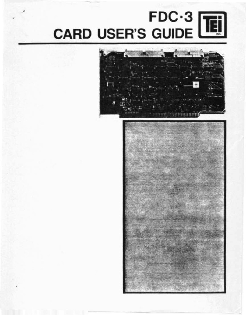
Trio Motion Coordinator MC216 Product manual

Trio Motion Technology
Motion Coordinator
Technical Reference Manual
Sixth Edition • 2004
Revision 4

All goods supplied by Trio are subject to Trio's standard terms and conditions of sale.
This manual applies to systems based on the Motion Coordinator MC202, Euro 205 and MC216 with sys-
tem software version 1.52, or higher. Or MC206 and MC224 with system software version 1.62, or
higher.
The material in this manual is subject to change without notice. Despite every effort, in a manual of
this scope errors and omissions may occur. Therefore Trio cannot be held responsible for any malfunc-
tions or loss of data as a result.
Revision 6.4 April 2004
Copyright (C) 2000-2004 Trio Motion Technology Ltd.
All Rights Reserved
UK
Trio Motion Technology Ltd.
Shannon Way
Tewkesbury
GL20 8ND
United Kingdom
Phone: +44 (0)1684 292333
Fax: +44 (0)1684 297929
USA
Trio Motion Technology LLC.
1000 Gamma Drive, Suite 206
Pittsburgh
PA 15238,
USA
Phone: +1 412 968 9744
Fax: +1 412 968 9746

SAFETY WARNING
During the installation or use of a control system, users of Trio products must
ensure there is no possibility of injury to any person, or damage to
machinery.
Control systems, especially during installation, can malfunction or behave
unexpectedly. Bearing this in mind, users must ensure that even in the event
of a malfunction or unexpected behaviour the safety of an operator or
programmer is never compromised.
!!


Motion Coordinator Technical Reference Manual
i
CONTENTS
INTRODUCTION . . . . . . . . . . . . . . . . . . . . . . . . . . . 1-1
Setup and Programming . . . . . . . . . . . . . . . . . . . . . . . . . . . . . 1-4
Products . . . . . . . . . . . . . . . . . . . . . . . . . . . . . . . . . . . . . . . 1-5
System Building . . . . . . . . . . . . . . . . . . . . . . . . . . . . . . . . . . 1-11
System Examples . . . . . . . . . . . . . . . . . . . . . . . . . . . . . . . 1-12
Features and Typical Applications . . . . . . . . . . . . . . . . . . . . 1-15
The Trio Motion Technology Website . . . . . . . . . . . . . . . . . . 1-16
HARDWARE OVERVIEW . . . . . . . . . . . . . . . . . . . . . . . 2-1
Motion Coordinator MC202 . . . . . . . . . . . . . . . . . . . . . . . . . . . 2-3
Connections to the MC202 . . . . . . . . . . . . . . . . . . . . . . . . . 2-4
Serial Port Connections . . . . . . . . . . . . . . . . . . . . . . . . . . . 2-7
MC202 - Feature Summary . . . . . . . . . . . . . . . . . . . . . . . . . 2-8
Motion Coordinator Euro205(X) . . . . . . . . . . . . . . . . . . . . . . . . 2-10
Axis Configuration . . . . . . . . . . . . . . . . . . . . . . . . . . . . . . 2-11
Connections to the Euro 205(X) . . . . . . . . . . . . . . . . . . . . . . 2-12
Euro 205(X) Backplane Connector . . . . . . . . . . . . . . . . . . . . 2-13
Euro205 - Feature Summary . . . . . . . . . . . . . . . . . . . . . . . . 2-19
Euro205X - Feature Summary . . . . . . . . . . . . . . . . . . . . . . . 2-20
Motion Coordinator MC206 . . . . . . . . . . . . . . . . . . . . . . . . . . . 2-22
Connections to the MC206 . . . . . . . . . . . . . . . . . . . . . . . . . 2-25
Amplifier Enable (Watchdog) Relay Output . . . . . . . . . . . . . . 2-28
Reference Encoder Input . . . . . . . . . . . . . . . . . . . . . . . . . . 2-29
Universal Serial Bus . . . . . . . . . . . . . . . . . . . . . . . . . . . . . 2-29
MC206 - Stepper Outputs / Encoder Inputs . . . . . . . . . . . . . . 2-30
MC206 - Feature Summary . . . . . . . . . . . . . . . . . . . . . . . . . 2-31
Motion Coordinator MC216 . . . . . . . . . . . . . . . . . . . . . . . . . . . 2-33
Connections to the MC216 . . . . . . . . . . . . . . . . . . . . . . . . . 2-35
MC216 - Feature Summary . . . . . . . . . . . . . . . . . . . . . . . . . 2-40
Motion Coordinator MC224 . . . . . . . . . . . . . . . . . . . . . . . . . . . 2-41
Connections to the MC224 . . . . . . . . . . . . . . . . . . . . . . . . . 2-43
MC224 - Feature Summary . . . . . . . . . . . . . . . . . . . . . . . . . 2-48
INSTALLATION . . . . . . . . . . . . . . . . . . . . . . . . . . . . 3-1
Motion Coordinator MC202 . . . . . . . . . . . . . . . . . . . . . . . . . . . 3-3
Motion Coordinator Euro 205 . . . . . . . . . . . . . . . . . . . . . . . 3-5
Motion Coordinator MC216 . . . . . . . . . . . . . . . . . . . . . . . . . . . 3-6
Motion Coordinator MC206 . . . . . . . . . . . . . . . . . . . . . . . . . . . 3-8

ii
Trio Motion Technology
EMC Considerations . . . . . . . . . . . . . . . . . . . . . . . . . . . . . . . . .3-9
Installation Requirements to Ensure Conformance . . . . . . . . . .3-11
Motion Coordinator MC202 . . . . . . . . . . . . . . . . . . . . . . . . .3-11
Motion Coordinator Euro 205 . . . . . . . . . . . . . . . . . . . . . . . .3-11
Motion Coordinator MC206 . . . . . . . . . . . . . . . . . . . . . . . . .3-12
Motion Coordinator MC216 . . . . . . . . . . . . . . . . . . . . . . . . .3-13
DAUGHTER BOARDS . . . . . . . . . . . . . . . . . . . . . . . . .4-1
Fitting and Handling Daughter Boards . . . . . . . . . . . . . . . . . . . . .4-4
MC216 + Axis Expander Slot Sequence . . . . . . . . . . . . . . . . . .4-6
Fitting Daughter Boards to the Euro205 . . . . . . . . . . . . . . . . . . . .4-7
Fitting Daughter Boards to the MC206 . . . . . . . . . . . . . . . . . . . . .4-9
Servo Encoder Daughter Board . . . . . . . . . . . . . . . . . . . . . . . . .4-11
Servo Resolver Daughter Board . . . . . . . . . . . . . . . . . . . . . . . . .4-14
Reference Encoder Daughter Board . . . . . . . . . . . . . . . . . . . . . .4-16
Stepper Daughter Board . . . . . . . . . . . . . . . . . . . . . . . . . . . . . .4-18
Stepper Encoder Daughter . . . . . . . . . . . . . . . . . . . . . . . . . . . .4-20
Hardware PSWITCH Daughter Board . . . . . . . . . . . . . . . . . . . . . .4-23
Analog Output Daughter Board . . . . . . . . . . . . . . . . . . . . . . . . .4-25
SSI Servo Encoder Daughter Board . . . . . . . . . . . . . . . . . . . . . . .4-26
Differential Stepper Daughter Board . . . . . . . . . . . . . . . . . . . . . .4-29
CAN Daughter Board . . . . . . . . . . . . . . . . . . . . . . . . . . . . . . . .4-31
SERCOS Daughter Board . . . . . . . . . . . . . . . . . . . . . . . . . . . . . .4-32
SLM Daughter Board . . . . . . . . . . . . . . . . . . . . . . . . . . . . . . . .4-33
USB Daughter Board . . . . . . . . . . . . . . . . . . . . . . . . . . . . . . . .4-35
Ethernet Daughter Board . . . . . . . . . . . . . . . . . . . . . . . . . . . . .4-36
Profibus Daughter Board . . . . . . . . . . . . . . . . . . . . . . . . . . . . .4-37
EXPANSION MODULES . . . . . . . . . . . . . . . . . . . . . . . .5-1
Input/Output Modules . . . . . . . . . . . . . . . . . . . . . . . . . . . . . . .5-3
CAN 16-I/O Module (P315) . . . . . . . . . . . . . . . . . . . . . . . . . .5-3
CAN Analog Inputs Module (P325) . . . . . . . . . . . . . . . . . . . . . . . .5-11
Operator Interfaces . . . . . . . . . . . . . . . . . . . . . . . . . . . . . . . . .5-15
Membrane Keypad (P503) . . . . . . . . . . . . . . . . . . . . . . . . . .5-16
Mini-Membrane Keypad (P502) . . . . . . . . . . . . . . . . . . . . . . .5-19
Programming the Membrane Keypad . . . . . . . . . . . . . . . . . . .5-20
Keypad KEY ON - KEY OFF Mode . . . . . . . . . . . . . . . . . . . . . .5-24
FO-VFKB Fibre Optic Keypad/Display Interface . . . . . . . . . . . . . . .5-26
FO-VFKB Keypad Interface . . . . . . . . . . . . . . . . . . . . . . . . . .5-26
Communications Adaptors . . . . . . . . . . . . . . . . . . . . . . . . . . . .5-28
Serial to RS485 Adapter: (P348) . . . . . . . . . . . . . . . . . . . . . .5-28
P349 - Serial to RS485 adapter to an MC202: . . . . . . . . . . . . . .5-30

Motion Coordinator Technical Reference Manual
iii
P435 - Serial to Fibre-Optic Adapter . . . . . . . . . . . . . . . . . . 5-31
SYSTEM SETUP AND DIAGNOSTICS . . . . . . . . . . . . . . . . . 6-1
Preliminary Concepts: . . . . . . . . . . . . . . . . . . . . . . . . . . . . . . 6-3
System Setup . . . . . . . . . . . . . . . . . . . . . . . . . . . . . . . . . 6-3
Preliminary checks . . . . . . . . . . . . . . . . . . . . . . . . . . . . . . 6-4
Checking Communications and System Configuration . . . . . . . 6-4
Input/Output Connections: . . . . . . . . . . . . . . . . . . . . . . . . 6-6
Setting Servo Gains . . . . . . . . . . . . . . . . . . . . . . . . . . . . . . . . 6-8
Proportional Gain . . . . . . . . . . . . . . . . . . . . . . . . . . . . . . . 6-10
Integral gain . . . . . . . . . . . . . . . . . . . . . . . . . . . . . . . . . . 6-10
Derivative gain . . . . . . . . . . . . . . . . . . . . . . . . . . . . . . . . 6-10
Output Velocity Gain . . . . . . . . . . . . . . . . . . . . . . . . . . . . 6-11
Velocity Feed Forward Gain . . . . . . . . . . . . . . . . . . . . . . . . 6-11
Diagnostic Checklists . . . . . . . . . . . . . . . . . . . . . . . . . . . . . . . 6-13
PROGRAMMING . . . . . . . . . . . . . . . . . . . . . . . . . . . 7-1
What is a program? . . . . . . . . . . . . . . . . . . . . . . . . . . . . . . 7-3
Sequence . . . . . . . . . . . . . . . . . . . . . . . . . . . . . . . . . . . . 7-4
Selection . . . . . . . . . . . . . . . . . . . . . . . . . . . . . . . . . . . . 7-5
Iteration . . . . . . . . . . . . . . . . . . . . . . . . . . . . . . . . . . . . . 7-5
Controller Functions . . . . . . . . . . . . . . . . . . . . . . . . . . . . . 7-7
. . . . . . . . . . . . . . . . . . . . . . . . . . . . . . . . . . . . . . . . . . 7-7
Identifiers . . . . . . . . . . . . . . . . . . . . . . . . . . . . . . . . . . . . 7-8
Expressions . . . . . . . . . . . . . . . . . . . . . . . . . . . . . . . . . . . 7-9
Parameters . . . . . . . . . . . . . . . . . . . . . . . . . . . . . . . . . . . 7-11
Command Line Interface . . . . . . . . . . . . . . . . . . . . . . . . . . 7-15
TRIO BASIC
COMMANDS . . . . . . . . . . . . . . . . . . . . . . . . . . . . . 8-1
Motion and Axis Commands . . . . . . . . . . . . . . . . . . . . . . . . . . . 8-11
Input / Output Commands . . . . . . . . . . . . . . . . . . . . . . . . . . . 8-45
Program Loops and Structures . . . . . . . . . . . . . . . . . . . . . . . . . 8-65
System Parameters and Commands . . . . . . . . . . . . . . . . . . . . . . 8-78
Process Parameters and Commands . . . . . . . . . . . . . . . . . . . . . 8-129
Mathematical Operations and Commands . . . . . . . . . . . . . . . . . . 8-133
Constants . . . . . . . . . . . . . . . . . . . . . . . . . . . . . . . . . . . . . . 8-150
Axis Parameters . . . . . . . . . . . . . . . . . . . . . . . . . . . . . . . . . . 8-152
PROGRAMMING EXAMPLES . . . . . . . . . . . . . . . . . . . . . 9-1
Example Programs . . . . . . . . . . . . . . . . . . . . . . . . . . . . . . . . . 9-3

iv
Trio Motion Technology
SUPPORT SOFTWARE . . . . . . . . . . . . . . . . . . . . . . . .10-1
Motion Perfect 2 . . . . . . . . . . . . . . . . . . . . . . . . . . . . . . . . . .10-3
System Requirements: . . . . . . . . . . . . . . . . . . . . . . . . . . . .10-4
New Features for Motion Perfect 1 Users . . . . . . . . . . . . . . . .10-5
Connecting Motion Perfect to a controller . . . . . . . . . . . . . . . . . .10-6
Motion Perfect 2 Projects . . . . . . . . . . . . . . . . . . . . . . . . . . . . .10-7
The Project Check Window . . . . . . . . . . . . . . . . . . . . . . . . .10-7
Project Check Options . . . . . . . . . . . . . . . . . . . . . . . . . . . .10-8
The Motion Perfect Desktop . . . . . . . . . . . . . . . . . . . . . . . . . . .10-11
Main Menu . . . . . . . . . . . . . . . . . . . . . . . . . . . . . . . . . . . .10-12
Controller Menu . . . . . . . . . . . . . . . . . . . . . . . . . . . . . . . .10-13
Controller Configuration . . . . . . . . . . . . . . . . . . . . . . . . . . .10-14
Feature Enable . . . . . . . . . . . . . . . . . . . . . . . . . . . . . . . . .10-15
Loading New System Software . . . . . . . . . . . . . . . . . . . . . . .10-17
Flashstick support . . . . . . . . . . . . . . . . . . . . . . . . . . . . . . .10-19
Lock / Unlock . . . . . . . . . . . . . . . . . . . . . . . . . . . . . . . . . .10-20
Motion Perfect Tools . . . . . . . . . . . . . . . . . . . . . . . . . . . . . . . .10-21
Terminal . . . . . . . . . . . . . . . . . . . . . . . . . . . . . . . . . . . . .10-22
Axis Parameters . . . . . . . . . . . . . . . . . . . . . . . . . . . . . . . .10-23
Oscilloscope . . . . . . . . . . . . . . . . . . . . . . . . . . . . . . . . . . .10-26
Keypad Emulation . . . . . . . . . . . . . . . . . . . . . . . . . . . . . . .10-35
Table / VR Editor . . . . . . . . . . . . . . . . . . . . . . . . . . . . . . . .10-37
Jog Axes . . . . . . . . . . . . . . . . . . . . . . . . . . . . . . . . . . . . .10-38
Digital IO Status . . . . . . . . . . . . . . . . . . . . . . . . . . . . . . . .10-42
Analogue Input Viewer . . . . . . . . . . . . . . . . . . . . . . . . . . . .10-44
Linking to External Tools . . . . . . . . . . . . . . . . . . . . . . . . . . . . .10-45
Control Panel . . . . . . . . . . . . . . . . . . . . . . . . . . . . . . . . . . . . .10-47
Creating and Running a program . . . . . . . . . . . . . . . . . . . . . . . .10-52
The Motion Perfect Editor . . . . . . . . . . . . . . . . . . . . . . . . . .10-53
Editor Menus . . . . . . . . . . . . . . . . . . . . . . . . . . . . . . . . . . .10-56
Program Debugger . . . . . . . . . . . . . . . . . . . . . . . . . . . . . . . . .10-58
Running Programs . . . . . . . . . . . . . . . . . . . . . . . . . . . . . . . . . .10-61
Making programs run automatically . . . . . . . . . . . . . . . . . . . . . .10-62
Set Powerup Mode . . . . . . . . . . . . . . . . . . . . . . . . . . . . . . .10-62
Storing Programs in the Flash EPROM . . . . . . . . . . . . . . . . . . . . .10-63
Configuring The Motion Perfect 2 Desktop . . . . . . . . . . . . . . . . . .10-64
Communications . . . . . . . . . . . . . . . . . . . . . . . . . . . . . . . .10-64
Changing Comms Port Parameters . . . . . . . . . . . . . . . . . . . . .10-65
Editor Options . . . . . . . . . . . . . . . . . . . . . . . . . . . . . . . . . .10-67
General Options . . . . . . . . . . . . . . . . . . . . . . . . . . . . . . . .10-67
Saving the Desktop Layout . . . . . . . . . . . . . . . . . . . . . . . . . .10-68
Running Motion Perfect 2 Without a Controller . . . . . . . . . . . . . .10-69

v
Trio Motion Technology
MC Simulation . . . . . . . . . . . . . . . . . . . . . . . . . . . . . . . . . .10-69
CAD2Motion . . . . . . . . . . . . . . . . . . . . . . . . . . . . . . . . . . . . . .10-72
DocMaker . . . . . . . . . . . . . . . . . . . . . . . . . . . . . . . . . . . . . . .10-73
Project Autoloader . . . . . . . . . . . . . . . . . . . . . . . . . . . . . . . . .10-74
Files . . . . . . . . . . . . . . . . . . . . . . . . . . . . . . . . . . . . . . . .10-75
. . . . . . . . . . . . . . . . . . . . . . . . . . . . . . . . . . . . . . . . . . .10-75
Running the program . . . . . . . . . . . . . . . . . . . . . . . . . . . . .10-76
Script Commands . . . . . . . . . . . . . . . . . . . . . . . . . . . . . . . .10-77
Script File . . . . . . . . . . . . . . . . . . . . . . . . . . . . . . . . . . . .10-82
FIBRE-OPTIC NETWORK . . . . . . . . . . . . . . . . . . . . . . .11-1
General Description . . . . . . . . . . . . . . . . . . . . . . . . . . . . . . . .11-3
Connection of Network . . . . . . . . . . . . . . . . . . . . . . . . . . . .11-4
Network Programming . . . . . . . . . . . . . . . . . . . . . . . . . . . . . . .11-6
Examples of network programming . . . . . . . . . . . . . . . . . . . .11-8
Network Specification . . . . . . . . . . . . . . . . . . . . . . . . . . . . . . .11-12
USING THE TRIO
ACTIVEX CONTROL . . . . . . . . . . . . . . . . . . . . . . . . .12-1
Introduction . . . . . . . . . . . . . . . . . . . . . . . . . . . . . . . . . . .12-3
Requirements . . . . . . . . . . . . . . . . . . . . . . . . . . . . . . . . . .12-3
Installation of the ActiveX Component . . . . . . . . . . . . . . . . . .12-3
Using the Component . . . . . . . . . . . . . . . . . . . . . . . . . . . . .12-3
Connection Commands . . . . . . . . . . . . . . . . . . . . . . . . . . . . . . .12-4
Properties . . . . . . . . . . . . . . . . . . . . . . . . . . . . . . . . . . . . . . .12-7
Motion Commands . . . . . . . . . . . . . . . . . . . . . . . . . . . . . . . . . .12-9
Process Control Commands . . . . . . . . . . . . . . . . . . . . . . . . . . . .12-18
Variable Commands . . . . . . . . . . . . . . . . . . . . . . . . . . . . . . . . .12-19
Input / Output Commands . . . . . . . . . . . . . . . . . . . . . . . . . . . .12-22
General commands . . . . . . . . . . . . . . . . . . . . . . . . . . . . . . . . .12-28
Events . . . . . . . . . . . . . . . . . . . . . . . . . . . . . . . . . . . . . . . . .12-30
TrioPC status . . . . . . . . . . . . . . . . . . . . . . . . . . . . . . . . . .12-31
COMMUNICATIONS PROTOCOLS . . . . . . . . . . . . . . . . . . .13-1
MODBUS RTU . . . . . . . . . . . . . . . . . . . . . . . . . . . . . . . . . . . . .13-3
Introduction . . . . . . . . . . . . . . . . . . . . . . . . . . . . . . . . . . .13-3
Initialisation and Set-up . . . . . . . . . . . . . . . . . . . . . . . . . . .13-3
Modbus Technical Reference . . . . . . . . . . . . . . . . . . . . . . . .13-4
Glossary . . . . . . . . . . . . . . . . . . . . . . . . . . . . . . . . . . . . . .13-7
Profibus . . . . . . . . . . . . . . . . . . . . . . . . . . . . . . . . . . . . . . . .13-8
Installation and Set-up . . . . . . . . . . . . . . . . . . . . . . . . . . . .13-8

vi
Trio Motion Technology
DeviceNet . . . . . . . . . . . . . . . . . . . . . . . . . . . . . . . . . . . . . . .13-13
Installation and Set-up . . . . . . . . . . . . . . . . . . . . . . . . . . . .13-13
DeviceNet Information . . . . . . . . . . . . . . . . . . . . . . . . . . . .13-13
Connection Types Implemented . . . . . . . . . . . . . . . . . . . . . .13-14
DeviceNet Objects Implemented . . . . . . . . . . . . . . . . . . . . .13-14
MC Object . . . . . . . . . . . . . . . . . . . . . . . . . . . . . . . . . . . .13-20
DeviceNet Status LEDs . . . . . . . . . . . . . . . . . . . . . . . . . . . .13-25
Ethernet . . . . . . . . . . . . . . . . . . . . . . . . . . . . . . . . . . . . . . . .13-26
Default IP Address . . . . . . . . . . . . . . . . . . . . . . . . . . . . . . .13-26
The Subnet Mask . . . . . . . . . . . . . . . . . . . . . . . . . . . . . . . .13-27
Connecting to the Trio Ethernet Daughter Board . . . . . . . . . . .13-28
REFERENCE . . . . . . . . . . . . . . . . . . . . . . . . . . . . . .1-1
ATYPE . . . . . . . . . . . . . . . . . . . . . . . . . . . . . . . . . . . . . . . . . .1-3
AXISSTATUS / ERRORMASK . . . . . . . . . . . . . . . . . . . . . . . . . . . .1-4
CONTROL . . . . . . . . . . . . . . . . . . . . . . . . . . . . . . . . . . . . . . .1-5
Communications Ports . . . . . . . . . . . . . . . . . . . . . . . . . . . . . . .1-5
Communications Errors . . . . . . . . . . . . . . . . . . . . . . . . . . . . . .1-6
MTYPE . . . . . . . . . . . . . . . . . . . . . . . . . . . . . . . . . . . . . . . . .1-7
NETSTAT . . . . . . . . . . . . . . . . . . . . . . . . . . . . . . . . . . . . . . . .1-7
Data Formats and Floating-Point Operations . . . . . . . . . . . . . . . .1-8
Single-Precision Floating Point Format . . . . . . . . . . . . . . . . . .1-8
Product Codes . . . . . . . . . . . . . . . . . . . . . . . . . . . . . . . . . . . .1-9

CHAPTER
CHAPTER0INTRODUCTION


Motion Coordinator Technical Reference Manual
Introduction 1-3
Trio Motion Technology’s range of Motion Coordinator products are designed to
enable the control of industrial machines with a minimum of external compo-
nents. The products may be combined to build a control system capable of driv-
ing a multi-axis machine and its auxiliary equipment. The Motion Coordinator
system allows you to control up to 16 servo or stepper motors, Digital I/O and
additional equipment such as keypads and displays from a single master. Up to
fifteen masters can be networked together using the Trio fibre optic network
allowing up to 180 axes of control. The controller is programmed using the Trio
BASIC programming language. This may be used to build stand-alone programs or
commands can be sent from an external computer.
Typical System Configuration
The
Motion
Coordinator system is modular, allowing the user to tailor the controller
to their specific needs, but also allowingthe flexibility to incorporate new modules if
needs should change.
ENCODER V+ V- R 0v
54321
9876
ENCODER V+ V- R 0v
54321
9876
IO8
IO9
IO10
IO11
IO12
IO13
IO14
IO15
I0
I1
I2
I3
I4
I5
I6
I7
24v
0v
Trio
8
9
10
11
12
13
14
15
0
OKNET
0
1
STATUS
1
2
3
4
5
6
7
0
1
2
3
4
5
6
7
8
9
10
11
12
13
14
15
1
2
4
8
16
32
OFF
MS NS
PR
DR 10 11 12 13 14 15 24v Ov98
765432100v 24v
NODE
ADDRESS
CAN16 -I/O
Trio 0
1
2
3
4
5
6
7
8
9
10
11
12
13
14
15
1
2
4
8
16
32
OFF
MS NS
PR
DR 10 11 12 13 14 15 24v Ov98
7654 32100v 24v
NODE
ADDRESS
CAN16 -I/O
Trio
7
4
1
-
8
5
2
0
9
6
3
.
Y
N
CLR
TrioMo tion Technology
PCforProgramming
OperatorInterface
MotionCoordinator
CANI/O
ServoDrive
PCforProgramming
ServoDrive
Motor
Motor

1-4 Introduction
Setup and Programming
Trio Motion Technology
Setup and Programming
To program the
Motion
Coordinator a PC is connected via an RS-232 or USB serial
link. The dedicated
Motion
Perfect program is normally used to provide a wide
range of programming facilities, on an IBM PC or 100% compatible microcomputer
running Windows.
Motion Perfect
Once connected to the
Motion
Coordinator, the user has direct access to
Trio
BASIC, which provides an easy, rapid way to develop control programs. All the
standard program constructs are provided; variables, loops, input/output, maths
and conditions. Extensions to this basic instruction set exist to permit a wide
variety of motion control facilities, such as single axis moves, synchronized multi
axis moves and unsynchronised multi axis moves as well as the control of the
digital I/O.
The
Motion
Coordinator range currently consists of the MC202, MC206, Euro 205X,
MC216 and MC224. These controllers feature multi-tasking BASIC. Multiple
Trio
BASIC programs can be constructed and run simultaneously to make programming
complex applications much easier.

Motion Coordinator Technical Reference Manual
Introduction 1-5
Products
Products
The range of Trio
Motion
Coordinator products covered by this manual:
Motion Coordinator Master Controllers
Product
Code Name Description
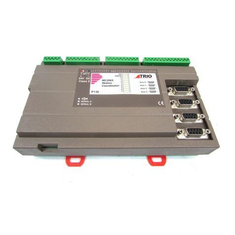
P165 MC202 Compact, low cost DIN-rail mounting module features 1 1/2
servo or 2 stepper axes. 4 Opto-isolated Inputs and 4 Opto-
isolated I/O channels are built in. Multi-tasking Trio BASIC. I/O
expansion is via CAN bus.
P135 MC206 Low cost, high performance DIN-rail mounting controller for 1-6
axes. 8 Opto-isolated Inputs and 8 Opto-isolated Input/Output
channels,1 Opto-isolated analogue input, USB and memory stick
socket are built in. Multi-tasking Trio BASIC. I/O expansion is
via CAN bus.
P150 Euro 205 For OEM applications, Trio offer a 3U Eurocard format controller
featuring 4 onboard axes plus the option for a further axis via a
standard Trio daughter board. 16 Opto-isolated Inputs and 8
Opto-isolated Output channels are built in. Multi-tasking Trio
BASIC. I/O expansion is via CAN bus.
P140 MC216 Flexible high performance master controller for 1-16 axes. 8
Opto-isolated Inputs and 8 Opto-isolated Input/Output channels
are built in. Multi-tasking Trio BASIC. I/O expansion is via CAN
bus.
P170 MC224 Flexible high performance master controller for 1-24 axes. 8
Opto-isolated Inputs and 8 Opto-isolated Input/Output
channels,2 Opto-isolated analogue inputs, USB and memory
stick socket are built in. Multi-tasking Trio BASIC. I/O
expansion is via CAN bus.

1-6 Introduction
Products
Trio Motion Technology
Daughter Boards
The Daughter Board concept
is a one of the key features
which give the
Motion
Coordinator system enormous
flexibility in its configuration.
The Daughter Boards provide
the interface to many types
of Servo or Stepper Axes, plus
a number of advanced
communications options as well.
There are 13 types of daughter boards currently available:
Product
Code: Name Description
P200 Servo Encoder +/- 10v Output, Differential Encoder Input
plus Hardware Registration Input
The servo encoder daughter board provides the inter-
face to a DC or Brushless servo motor fitted with an
encoder or encoder emulation.
P210 Servo Resolver +/- 10v Output, Resolver Input
plus Hardware Registration Input
The servo resolver daughter board provides the inter-
face to a DC or Brushless servo motor fitted with a
resolver. The resolver port provides absolute position
feedback within one motor turn.
P220 Reference
Encoder Differential Encoder Input
plus Hardware Registration Input
The encoder daughter board provides an encoder input
without any servo feedback facility for measurement,
registration and synchronization functions on convey-
ors, drums, flying shears, etc.
P230 Stepper Open-collector Step, Direction, Boost and Enable out-
puts
The stepper daughter board generates pulses to drive
an external stepper motor amplifier. Single step, half
step and micro-stepping drives can be used with the
board.

1-7 Introduction
Products
Trio Motion Technology
P240 Stepper
Encoder Open-collector Step, Direction, Boost and Enable out-
puts plus Differential Encoder Input.
The stepper daughter board with position verification
has all the features of the simpler stepper daughter
board. Position verification is added to a stepper axis
by providing encoder feedback to check the position of
the motor.
P242 Hardware
Pswitch Differential Encoder Input
plus Hardware Position Switch Outputs
The hardware PSWITCH daughter board allows 4 open-
collector outputs to be switched ON and OFF at pro-
grammed positions. This function is similar to the
PWITCH command which is implemented in the system
software and allows outputs to be switched ON and OFF
over defined position sectors. The Hardware PSWITCH
daughter board performs the position comparison in
electronic hardware on the daughter board. This allows
the pulses generated to be very accurately timed.
P260 Analogue Out-
put +/- 10v Output with direct DAC control
The voltage output daughter board provides a 12 bit +/-
10v voltage output for driving inverters and other
devices. The board is a simplified servo daughter board
and the connections are similar.
P270 SSI Absolute
Servo +/- 10v Output, Differential Encoder Input
plus Hardware Registration Input
The servo resolver daughter board provides the inter-
face to a DC or Brushless servo motor fitted with an
absolute encoder fitted with a Synchronous Serial Inter-
face (SSI).
P280 Differential
Stepper Differential Line Driver outputs for Step, Direction,
Boost and Enable, plus Hardware Registration Input
The differential stepper daughter board is a stepper
daughter board with the output signals provided as dif-
ferential 5 volt signals on a 15 way 'D' connector. The
daughter board does not feature an encoder port for
position verification, but does have a registration input
to allow for capture of the number of step pulses when
a registration signals arrives.
Product
Code: Name Description

1-8 Introduction
Products
Trio Motion Technology
*
(Available for use with MC206 and MC224 only)
Custom Daughter Boards
Trio can produce custom daughter boards for specific customer applications where
required.
P290 CAN Digital Link to CANBus drives
The combination of the motherboard CAN channel and
the ability to add up to 4 CAN daughter boards allows
the MC216 to potentially control up to 5 CAN channels.
P291* SERCOS Digital Link to SERCOS drives
The SERCOS daughter board provids digital control to
appropriate servo drives via a Fibre Optic loop. Up to 8
axes can be connected to each P291, which allows the
MC224 to control up to 24 axes.
P292 SLM (Drivelink) Digital Link to SLM drives
The SLM daughter board is aimed at providing digital
control channels for servo drives utilising the SLM proto-
col.
P295 USB Interface Universal Serial bus interface for high-speed PC
communications
The USB daughter board provides a very high speed
interface between the motion coordinator and a host
PC fitted with a USB port. Support for this high speed
interface is included in Trio's MotionPerfect 2 applica-
tion and software libraries are in development to allow
developers to support the interface within their own
programs.
P296* Ethernet Ethernet LAN Interface
The Ethernet daughter board enables the Motion Coor-
dinator to be connected to a local factory or office net-
work. Supports TCP/IP using the 10Base-T physical
layer.
P297 Profibus Profibus Fieldbus Interface
With the Profibus Daughter Board and appropriate soft-
ware on the Motion Coordinator, it is possible to con-
nect to external devices using the Profibus protocol.
Product
Code: Name Description

1-9 Introduction
Products
Trio Motion Technology
I/O Expansion options
MC216 Shown with P300 Axis Expander
Prod.
Code Name Description
P315 CAN 16 IO DIN Rail mounted 24v I/O expander module pro-
vides 16 opto-isolated channels each of which may
be used as an Input or an Output.
P325 CAN Analog Inputs DIN Rail mounted +/- 10v Analog Input module pro-
vides 8 opto-isolated channels.
P300 Axis Expander Expansion module provides housing for up to 4
additional axisdaughter boards. Up to 3 connect to
the MC216
P315 - CAN-16 I/O P325 - CAN-8 Analog Inputs

1-10 Introduction
Products
Trio Motion Technology
Operator Interfaces
Name Name Description
P502 Mini-Membrane
Keypad Compact operator keypad/display
P503 Membrane Keypad High performance general purpose operator key-
pad/display
This manual suits for next models
4
Table of contents
Other Trio Controllers manuals

Trio
Trio MC508 Instruction Manual
Trio
Trio MC664 User manual

Trio
Trio MC664 Instruction Manual
Trio
Trio MC405 Instruction Manual
Trio
Trio MC403-X User manual
Trio
Trio MC302X Instruction Manual
Trio
Trio MC508 P848 User manual
Trio
Trio MC302X Product manual
Trio
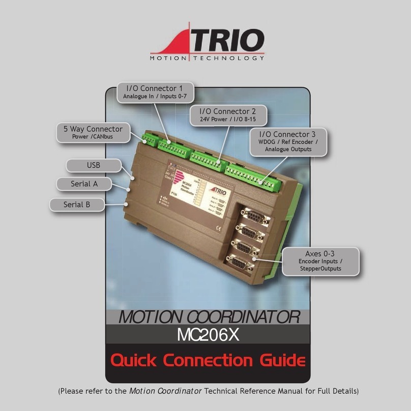
Trio MC206X Instruction Manual
Trio
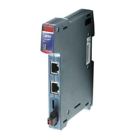
Trio Flex-6 Nano P601 User manual
