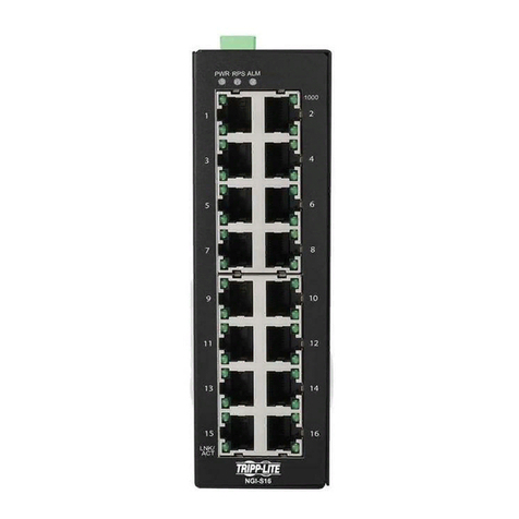
Tripp Lite NGI-M05-C1 User manual

1
COPYRIGHT
All rights reserved. No part of this publication may be reproduced, stored in a retrieval
system, or transmitted in any form or by any means, whether electronic, mechanical,
photo copying, recording or otherwise, without the prior written permission of the
publisher.
FCC WARNING
This equipment has been tested and found to comply with the limits for a class
A device, pursuant to part 15 of FCC rules. These limits are designed to provide
reasonable protection against harmful interference in a commercial installation.
This equipment generates uses and can radiate radio frequency energy and, if not
installed and used in accordance with the instructions, may cause harmful interference
to radio communication. Operation of this equipment in a residential area is likely to
cause harmful interference, in which case, the user will be required to correct the
interference at the user’s own expense.
CE
This is a Class A product. In a domestic environment, this product may cause
radio interference in which case the user may be required to take adequate
measures.
HOT & COLD WARNING
The Switch surface will be getting very hot or cold depend on the operating
environment. Please take special care when touch to the working switch.

2
Take special care to read and understand all the content in the
warning boxes.
Do not work on the system or connect or disconnect cables during
periods of lightning activity.
Before working on equipment that is connected to power lines,
remove jewelry (including rings, necklaces and watches). Metal
objects will heat up when connected to power and ground and can
cause serious burns or weld the metal object to the terminals.
Do not stack the chassis on any other equipment. If the chassis falls,
it can cause severe bodily injury and equipment damage.
An exposed wire lead from a DC-input power source can conduct
harmful levels of electricity. Be sure that no exposed portion of the
DC-input power source wire extends from the terminal block plug.
Ethernet cables must be shielded when used in a central office
environment.
If a redundant power system (RPS) is not connected to the switch,
install an RPS connector cover on the back of the switch.
Warning
Warning
Warning
Warning
Warning
Warning
Warning

3
Read the wall-mounting instructions carefully before beginning
installation. Failure to use the correct hardware or to follow the correct
procedures could result in a hazardous situation to people and
damage to the system.
Before performing any of the following procedures, ensure that power
is removed from the DC circuit.
Read the installation instructions before connecting the system to the
power source.
To prevent bodily injury when mounting or servicing this unit in a rack,
you must take special precautions to ensure that the system remains
stable. The following guidelines are provided to ensure your safety:
This unit should be mounted at the bottom of the rack if it
is the only unit in the rack.
When mounting this unit in a partially filled rack, load the
rack from the bottom to the top with the heaviest
component at the bottom of the rack.
If the rack is provided with stabilizing devices, install the
stabilizers before mounting or servicing the unit in the rack.
This unit might have more than one power supply connection. All
connections must be removed to de-energize the unit.
Only trained and qualified personnel should be allowed to install,
replace or service this equipment.
Warning
Warning
Warning
Warning
Warning
Warning

4
When installing or replacing the unit, the ground connection must
always be made first and disconnected last.
Voltages that present a shock hazard may exist on Power over
Ethernet (PoE) circuits if interconnections are made using
uninsulated exposed metal contacts, conductors or terminals. Avoid
using such interconnection methods, unless the exposed metal parts
are located within a restricted access location and users and service
people who are authorized within the restricted access location are
made aware of the hazard. A restricted access area can be accessed
only through the use of a special tool, lock and key or other means
of security.
No user-serviceable parts inside. Do not open.
This equipment must be grounded. Never defeat the ground
conductor or operate the equipment in the absence of a suitably
installed ground conductor. Contact the appropriate electrical
inspection authority or an electrician if you are uncertain that suitable
grounding is available.
Warning
Warning
Warning
Warning

5
Table of Contents
1. ABOUT THIS MANUAL...............................................................................12
1.1. INTRODUCTION.....................................................................................................12
1.2. PURPOSE ..............................................................................................................12
1.3. TERMS/USAGE .....................................................................................................12
2. ABOUT THE NGI-M05-C1 ...........................................................................13
2.1. FEATURES ............................................................................................................13
2.2. SPECIFICATIONS ...................................................................................................13
3. HARDWARE DESCRIPTION.......................................................................15
3.1. CONNECTORS .......................................................................................................15
3.2. INSTALLATION ......................................................................................................16
3.3. LED INDICATORS..................................................................................................21
3.4. DIP SWITCHES .....................................................................................................21
4. SYSTEM STATUS.........................................................................................23
4.1. CONSOLE PORT ....................................................................................................23
4.2. TELNET ................................................................................................................23
4.3. HOW TO ENTER THE CLI? .....................................................................................23
4.4. CLI COMMAND CONCEPT .....................................................................................24
4.5. MANAGEMENT VIA INTERNET BROWSER INTERFACE ..............................................26
4.6. SYSTEM INFORMATION..........................................................................................27
4.6.1. CLI CONFIGURATION .................................................................................................... 27
4.6.2. WEB CONFIGURATION .................................................................................................. 28
5. BASIC SETTINGS........................................................................................30
5.1. SYSTEM SETTINGS ................................................................................................30
5.1.1. SYSTEM ......................................................................................................................... 30
5.1.1.1. CLI CONFIGURATION .................................................................................................... 30
5.1.1.2. WEB CONFIGURATION .................................................................................................. 32
5.1.2. JUMBO FRAME............................................................................................................... 34
5.1.2.1. CLI CONFIGURATION .................................................................................................... 34
5.1.2.2. WEB CONFIGURATION .................................................................................................. 34
5.1.3. SNTP............................................................................................................................. 35
5.1.3.1. CLI CONFIGURATION .................................................................................................... 35
5.1.3.2. WEB CONFIGURATION .................................................................................................. 37
5.1.4. MANAGEMENT HOST .................................................................................................... 39
5.1.4.1. CLI CONFIGURATION .................................................................................................... 39
5.1.4.2. WEB CONFIGURATION .................................................................................................. 40
5.2. MAC MANAGEMENT ............................................................................................41
5.2.1. STATIC MAC................................................................................................................. 42

6
5.2.1.1. CLI CONFIGURATION .................................................................................................... 42
5.2.1.2. WEB CONFIGURATION .................................................................................................. 42
5.2.2. MAC TABLE.................................................................................................................. 44
5.2.2.1. CLI CONFIGURATION .................................................................................................... 44
5.2.2.2. WEB CONFIGURATION .................................................................................................. 44
5.2.3. AGE TIME ...................................................................................................................... 46
5.2.3.1. CLI CONFIGURATION .................................................................................................... 46
5.2.3.2. WEB CONFIGURATION .................................................................................................. 46
5.3. PORT MIRROR ......................................................................................................47
5.3.1. CLI CONFIGURATION .................................................................................................... 47
5.3.2. WEB CONFIGURATION .................................................................................................. 48
5.4. PORT SETTINGS ....................................................................................................50
5.4.1. GENERAL SETTINGS ...................................................................................................... 51
5.4.1.1. CLI CONFIGURATION .................................................................................................... 51
5.4.1.2. WEB CONFIGURATION .................................................................................................. 54
5.4.2. INFORMATION ............................................................................................................... 55
5.4.2.1. CLI CONFIGURATION .................................................................................................... 55
5.4.2.2. WEB CONFIGURATION .................................................................................................. 56
6. ADVANCED SETTINGS...............................................................................58
6.1. BANDWIDTH CONTROL .........................................................................................58
6.1.1. QOS ............................................................................................................................... 58
6.1.1.1. PORT PRIORITY ............................................................................................................. 61
6.1.1.1.1. CLI CONFIGURATION .................................................................................................... 61
6.1.1.1.2. WEB CONFIGURATION .................................................................................................. 61
6.1.1.2. IP DIFFSERV (DSCP) .................................................................................................... 63
6.1.1.2.1. CLI CONFIGURATION .................................................................................................... 64
6.1.1.2.2. WEB CONFIGURATION .................................................................................................. 65
6.1.1.3. PRIORITY/QUEUE MAPPING .......................................................................................... 66
6.1.1.3.1. CLI CONFIGURATION .................................................................................................... 66
6.1.1.3.2. WEB CONFIGURATION .................................................................................................. 67
6.1.1.4. SCHEDULE MODE .......................................................................................................... 68
6.1.1.4.1. CLI CONFIGURATION .................................................................................................... 68
6.1.1.4.2. WEB CONFIGURATION .................................................................................................. 69
6.1.2. RATE LIMITATION ......................................................................................................... 70
6.1.2.1. STORM CONTROL .......................................................................................................... 70
6.1.2.1.1. CLI CONFIGURATION .................................................................................................... 70
6.1.2.1.2. WEB CONFIGURATION .................................................................................................. 72
6.1.2.2. BANDWIDTH LIMITATION ............................................................................................. 73
6.1.2.2.1. CLI CONFIGURATION .................................................................................................... 73
6.1.2.2.2. WEB CONFIGURATION .................................................................................................. 74
6.2. IGMP SNOOPING ..................................................................................................75
6.2.1. IGMP SNOOPING........................................................................................................... 75
6.2.1.1. GENERAL SETTINGS ...................................................................................................... 77
6.2.1.1.1. CLI CONFIGURATION .................................................................................................... 77
6.2.1.1.2. WEB CONFIGURATION .................................................................................................. 77
6.2.1.2. PORT SETTINGS ............................................................................................................. 79
6.2.1.2.1. CLI CONFIGURATION .................................................................................................... 79
6.2.1.2.2. WEB CONFIGURATION .................................................................................................. 81
6.2.1.3. QUERIER SETTINGS ....................................................................................................... 83

7
6.2.1.3.1. CLI CONFIGURATION .................................................................................................... 83
6.2.1.3.2. WEB CONFIGURATION .................................................................................................. 84
6.2.2. IGMP SNOOPING FILTERING......................................................................................... 85
6.2.2.1. GENERAL SETTINGS ...................................................................................................... 85
6.2.2.1.1. CLI CONFIGURATION .................................................................................................... 85
6.2.2.1.2. WEB CONFIGURATION .................................................................................................. 85
6.2.2.2. MULTICAST GROUP..................................................................................................... 87
6.2.2.2.1. CLI CONFIGURATION .................................................................................................... 87
6.2.2.2.2. WEB CONFIGURATION .................................................................................................. 87
6.2.2.3. PORT SETTINGS ........................................................................................................... 88
6.2.2.3.1. CLI CONFIGURATION .................................................................................................... 88
6.2.2.3.2. WEB CONFIGURATION .................................................................................................. 89
6.2.3. MULTICAST ADDRESS ................................................................................................... 90
6.2.3.1. CLI CONFIGURATION .................................................................................................... 91
6.2.3.2. WEB CONFIGURATION .................................................................................................. 92
6.3. VLAN ..................................................................................................................93
6.3.1. PORT ISOLATION ........................................................................................................... 93
6.3.1.1. CLI CONFIGURATIONS .................................................................................................. 93
6.3.1.2. WEB CONFIGURATIONS................................................................................................. 94
6.3.2. 802.1Q VLAN............................................................................................................... 95
6.3.2.1. VLAN SETTINGS........................................................................................................... 96
6.3.2.1.1. CLI CONFIGURATIONS .................................................................................................. 96
6.3.2.1.2. WEB CONFIGURATIONS................................................................................................. 97
6.3.2.2. TAG SETTINGS............................................................................................................... 99
6.3.2.2.1. CLI CONFIGURATIONS .................................................................................................. 99
6.3.2.2.2. WEB CONFIGURATIONS............................................................................................... 100
6.3.2.3. PORT SETTINGS ........................................................................................................... 101
6.3.2.3.1. CLI CONFIGURATIONS ................................................................................................ 101
6.3.2.3.2. WEB CONFIGURATIONS............................................................................................... 102
6.3.3. MAC VLAN ............................................................................................................... 103
6.3.3.1. CLI CONFIGURATIONS ................................................................................................ 103
6.3.3.2. WEB CONFIGURATIONS............................................................................................... 104
6.3.4. Q-IN-Q VLAN (VLAN STACKING) ............................................................................ 105
6.3.4.1. VLAN STACKING........................................................................................................ 107
6.3.4.1.1. CLI CONFIGURATIONS ................................................................................................ 107
6.3.4.1.2. WEB CONFIGURATIONS............................................................................................... 108
6.3.4.2. PORT-BASED Q-IN-Q................................................................................................... 109
6.3.4.2.1. CLI CONFIGURATIONS ................................................................................................ 110
6.3.4.2.2. WEB CONFIGURATIONS............................................................................................... 111
6.4. DHCP OPTION (OPTION 82) ................................................................................113
6.4.1. CLI CONFIGURATIONS ................................................................................................ 115
6.4.2. WEB CONFIGURATIONS............................................................................................... 116
6.5. DHCP RELAY .....................................................................................................118
6.5.1. CLI CONFIGURATIONS ................................................................................................ 119
6.5.2. WEB CONFIGURATIONS............................................................................................... 120
6.6. DUAL HOMING....................................................................................................121
6.6.1. CLI CONFIGURATIONS ................................................................................................ 123
6.6.2. WEB CONFIGURATIONS............................................................................................... 124
6.7. EEE ...................................................................................................................126
6.7.1. CLI CONFIGURATIONS ................................................................................................ 126
6.7.2. WEB CONFIGURATIONS............................................................................................... 126

8
6.8. ERPS .................................................................................................................128
6.8.1. RING SETTINGS ........................................................................................................... 130
6.8.1.1. CLI CONFIGURATIONS ................................................................................................ 130
6.8.1.2. WEB CONFIGURATIONS............................................................................................... 131
6.8.2. INSTANCE .................................................................................................................... 133
6.8.2.1. CLI CONFIGURATIONS ................................................................................................ 133
6.8.2.2. WEB CONFIGURATIONS............................................................................................... 134
6.9. LINK AGGREGATION ...........................................................................................135
6.9.1. STATIC TRUNK ............................................................................................................ 135
6.9.1.1. CLI CONFIGURATIONS ................................................................................................ 135
6.9.1.2. WEB CONFIGURATIONS............................................................................................... 136
6.9.2. LACP .......................................................................................................................... 137
6.9.2.1. CLI CONFIGURATIONS ................................................................................................ 138
6.9.2.2. WEB CONFIGURATIONS............................................................................................... 139
6.9.3. LACP INFORMATION .................................................................................................. 140
6.9.3.1. CLI CONFIGURATIONS ................................................................................................ 140
6.9.3.2. WEB CONFIGURATIONS............................................................................................... 140
6.10. LOOP DETECTION ...............................................................................................142
6.10.1. CLI CONFIGURATIONS ................................................................................................ 142
6.10.2. WEB CONFIGURATIONS............................................................................................... 144
6.11. MODBUS TCP .....................................................................................................146
6.11.1. CLI CONFIGURATIONS ................................................................................................ 149
6.11.2. WEB CONFIGURATIONS............................................................................................... 150
6.12. STP /RSTP ........................................................................................................152
6.12.1. GENERAL SETTINGS .................................................................................................... 157
6.12.1.1. CLI CONFIGURATIONS ................................................................................................ 157
6.12.1.2. WEB CONFIGURATIONS............................................................................................... 158
6.12.2. PORT PARAMETERS ..................................................................................................... 159
6.12.2.1. CLI CONFIGURATIONS ................................................................................................ 159
6.12.2.2. WEB CONFIGURATIONS............................................................................................... 161
6.12.3. STP STATUS ................................................................................................................ 163
6.12.3.1. CLI CONFIGURATIONS ................................................................................................ 163
6.12.3.2. WEB CONFIGURATIONS............................................................................................... 163
7. SECURITY .................................................................................................165
7.1. IP SOURCE GUARD..............................................................................................165
7.1.1. DHCP SNOOPING ........................................................................................................ 165
7.1.1.1. DHCP SNOOPING ........................................................................................................ 168
7.1.1.1.1. CLI CONFIGURATIONS ................................................................................................ 168
7.1.1.1.2. WEB CONFIGURATIONS............................................................................................... 169
7.1.1.2. PORT SETTINGS ........................................................................................................... 170
7.1.1.2.1. CLI CONFIGURATIONS ................................................................................................ 170
7.1.1.2.2. WEB CONFIGURATIONS............................................................................................... 171
7.1.1.3. SERVER SCREENING .................................................................................................... 172
7.1.1.3.1. CLI CONFIGURATIONS ................................................................................................ 172
7.1.1.3.2. WEB CONFIGURATIONS............................................................................................... 172
7.1.2. BINDING TABLE .......................................................................................................... 173
7.1.2.1. STATIC ENTRY ............................................................................................................ 173
7.1.2.1.1. CLI CONFIGURATIONS ................................................................................................ 173
7.1.2.1.2. WEB CONFIGURATIONS............................................................................................... 174

9
7.1.2.2. BINDING TABLE .......................................................................................................... 175
7.1.2.2.1. CLI CONFIGURATIONS ................................................................................................ 175
7.1.2.2.2. WEB CONFIGURATIONS............................................................................................... 175
7.1.3. ARP INSPECTION......................................................................................................... 176
7.1.3.1. ARP INSPECTION......................................................................................................... 177
7.1.3.1.1. CLI CONFIGURATIONS ................................................................................................ 177
7.1.3.1.2. WEB CONFIGURATIONS............................................................................................... 178
7.1.3.2. FILTER TABLE ............................................................................................................. 180
7.1.3.2.1. CLI CONFIGURATIONS ................................................................................................ 180
7.1.3.2.2. WEB CONFIGURATIONS............................................................................................... 181
7.2. ACCESS CONTROL LIST .......................................................................................182
7.2.1. CLI CONFIGURATIONS ................................................................................................ 183
7.2.2. WEB CONFIGURATIONS............................................................................................... 185
7.3. 802.1X................................................................................................................188
7.3.1. GLOBAL SETTINGS ...................................................................................................... 191
7.3.1.1. CLI CONFIGURATIONS ................................................................................................ 191
7.3.1.2. WEB CONFIGURATIONS............................................................................................... 192
7.3.2. PORT SETTINGS ........................................................................................................... 194
7.3.2.1. CLI CONFIGURATIONS ................................................................................................ 194
7.3.2.2. WEB CONFIGURATIONS............................................................................................... 195
7.4. PORT SECURITY..................................................................................................197
7.4.1. CLI CONFIGURATIONS ................................................................................................ 197
7.4.2. WEB CONFIGURATIONS............................................................................................... 198
8. MONITOR..................................................................................................199
8.1. ALARM...............................................................................................................199
8.1.1. CLI CONFIGURATIONS ................................................................................................ 199
8.1.2. WEB CONFIGURATIONS............................................................................................... 199
8.2. PORT STATISTICS ................................................................................................200
8.2.1. CLI CONFIGURATIONS ................................................................................................ 200
8.2.2. WEB CONFIGURATIONS............................................................................................... 200
8.3. PORT UTILIZATION .............................................................................................201
8.3.1. CLI CONFIGURATIONS ................................................................................................ 201
8.3.2. WEB CONFIGURATIONS............................................................................................... 201
8.4. RMON STATISTICS .............................................................................................202
8.4.1. CLI CONFIGURATIONS ................................................................................................ 202
8.4.2. WEB CONFIGURATIONS............................................................................................... 202
8.5. SFP INFORMATION .............................................................................................203
8.5.1. CLI CONFIGURATIONS ................................................................................................ 203
8.5.2. WEB CONFIGURATIONS............................................................................................... 203
8.6. TRAFFIC MONITOR .............................................................................................204
8.6.1. CLI CONFIGURATIONS ................................................................................................ 204
8.6.2. WEB CONFIGURATIONS............................................................................................... 205
9. MANAGEMENT ........................................................................................207
9.1. SNMP ................................................................................................................207
9.1.1. SNMP.......................................................................................................................... 207
9.1.1.1. SNMP SETTINGS ......................................................................................................... 207
9.1.1.1.1. CLI CONFIGURATIONS ................................................................................................ 207

10
9.1.1.1.2. WEB CONFIGURATIONS............................................................................................... 209
9.1.1.2. COMMUNITY NAME..................................................................................................... 210
9.1.1.2.1. CLI CONFIGURATIONS ................................................................................................ 210
9.1.1.2.2. WEB CONFIGURATIONS............................................................................................... 211
9.1.2. SNMP TRAP ................................................................................................................ 213
9.1.2.1. RECEIVER SETTINGS ................................................................................................... 213
9.1.2.1.1. CLI CONFIGURATIONS ................................................................................................ 213
9.1.2.1.2. WEB CONFIGURATIONS............................................................................................... 213
9.1.2.2. EVENT SETTINGS......................................................................................................... 214
9.1.2.2.1. CLI CONFIGURATIONS ................................................................................................ 215
9.1.2.2.2. WEB CONFIGURATIONS............................................................................................... 216
9.1.2.3. PORT EVENT SETTINGS ............................................................................................... 216
9.1.2.3.1. CLI CONFIGURATIONS ................................................................................................ 216
9.1.2.3.2. WEB CONFIGURATIONS............................................................................................... 218
9.1.3. SNMPV3 ..................................................................................................................... 219
9.1.3.1. SNMPV3GROUP ......................................................................................................... 219
9.1.3.1.1. CLI CONFIGURATIONS ................................................................................................ 219
9.1.3.1.2. WEB CONFIGURATIONS............................................................................................... 219
9.1.3.2. SNMPV3USER............................................................................................................ 220
9.1.3.2.1. CLI CONFIGURATIONS ................................................................................................ 220
9.1.3.2.2. WEB CONFIGURATIONS............................................................................................... 221
9.1.3.3. SNMPV3VIEW ........................................................................................................... 222
9.1.3.3.1. CLI CONFIGURATIONS ................................................................................................ 222
9.1.3.3.2. WEB CONFIGURATIONS............................................................................................... 222
9.2. AUTO PROVISION................................................................................................223
9.2.1. CLI CONFIGURATIONS ................................................................................................ 224
9.2.2. WEB CONFIGURATIONS............................................................................................... 225
9.3. MAIL ALARM......................................................................................................225
9.3.1. CLI CONFIGURATIONS ................................................................................................ 226
9.3.2. WEB CONFIGURATIONS............................................................................................... 227
9.4. MAINTENANCE ...................................................................................................229
9.4.1. CONFIGURATION ......................................................................................................... 229
9.4.1.1. CLI CONFIGURATIONS ................................................................................................ 229
9.4.1.2. WEB CONFIGURATIONS............................................................................................... 230
9.4.2. FIRMWARE .................................................................................................................. 231
9.4.2.1. CLI CONFIGURATIONS ................................................................................................ 231
9.4.2.2. WEB CONFIGURATIONS............................................................................................... 232
9.4.3. REBOOT ....................................................................................................................... 233
9.4.3.1. CLI CONFIGURATIONS ................................................................................................ 233
9.4.3.2. WEB CONFIGURATIONS............................................................................................... 233
9.4.4. SERVER CONTROL....................................................................................................... 234
9.4.4.1. CLI CONFIGURATIONS ................................................................................................ 234
9.4.4.2. WEB CONFIGURATIONS............................................................................................... 235
9.5. SYS LOG .............................................................................................................236
9.5.1. CLI CONFIGURATIONS ................................................................................................ 236
9.5.2. WEB CONFIGURATIONS............................................................................................... 237
9.6. USER ACCOUNT ..................................................................................................238
9.6.1. CLI CONFIGURATION .................................................................................................. 238
9.6.2. WEB CONFIGURATION ................................................................................................ 239
9.7. DEVICE MANAGEMENT .......................................................................................240
9.7.1. LLDP .......................................................................................................................... 240

11
9.7.1.1. CLI CONFIGURATION .................................................................................................. 240
9.7.1.2. WEB CONFIGURATION ................................................................................................ 241
9.7.2. MANUAL REGISTRATION ............................................................................................ 243
9.7.2.1. CLI CONFIGURATIONS ................................................................................................ 243
9.7.2.2. WEB CONFIGURATIONS............................................................................................... 243
9.7.3. ONVIF ........................................................................................................................ 245
9.7.3.1. CLI CONFIGURATIONS ................................................................................................ 245
9.7.3.2. WEB CONFIGURATIONS............................................................................................... 245
9.8. TOPOLOGY MAP .................................................................................................247
9.8.1. BACKGROUND CONFIGURATION................................................................................. 249
9.8.2. CLIENT-SWITCH MANAGEMENT ................................................................................. 251
10. MISC ..........................................................................................................251
10.1. CABLE TEST .......................................................................................................251
10.1.1. CLI CONFIGURATIONS ................................................................................................ 251
WARRANTY & PRODUCT REGISTRATION……….……………..…………………255

12
1. About this Manual
1.1. Introduction
The NGI-M05-C1 managed industrial switch is engineered with rugged hardware to meet
the high reliability requirements of Industrial applications. Built in a well-protected IP-30
aluminum housing, the switch withstands in operating temperatures ranging from -40°C
to 75°C and operates consistently even in harsh industrial environments. The NGI-M05-
C1 supports QoS, IGMP snooping, SFP DDMI and other device management features to
fulfill the needs of high performance managed Industrial networks.
The switch is complied with 4-10/100/1000Base-T copper ports to deliver gigabit
performance for most demanding industrial applications. Two gigabit fiber slots of the
switch can be configured as dual fiber ring ports to quickly recover network failures and
provide an easy way to establish redundant gigabit network. Thus, NGI-M05-C1 ensures
a reliable and highly available managed industrial network.
1.2. Purpose
This guide describes how to install and configure the NGI-M05-C1 Industrial Managed
Switch.
1.3. Terms/ Usage
In this manual, the term “Switch” (first letter upper case) refers to the NGI-M05-C1 Switch,
and “switch” (first letter lower case) refers to other switches.

13
2. About the NGI-M05-C1
2.1. Features
Network Functions
Port-based Mirroring
256 Active VLAN
IGMP Snooping v1/v2/v3
IGMP Querier
DHCP Relay/Option 82
Link Aggregation
Link Layer Discovery Protocol
Loop Detection, Auto Recovery Timer
STP/RSTP
SFP DDMI Support
RMON Statistics
Network Security
Access Control List (L2/L3/L4)
Port Security
802.1x Port Authentication
DHCP Snooping
Traffic Management & QoS
Port Priority
Rate Limitation
Storm Control
Port Isolation
802.1Q Tag-based VLAN
Auto MDI/MDI-X
Network Management
Command Line Interface, Telnet
Web GUI
SNMP v1/v2c
Management VLAN
System log
Firmware Upgradable
Configuration Upload/Download
LED, SNMP trap and email alarm
2.2. Specifications
IEEE Standards
IEEE 802.3 10Base-T
IEEE 802.3u 100Base-TX/FX
IEEE 802.3ab 1000Base-T
IEEE 802.3z 1000Base-SX/LX
IEEE 802.3x Flow Control
IEEE 802.3 Nway Auto-negotiation
IEEE 802.3az EEE, Energy Efficient Ethernet
IEEE 802.1ab Link Layer Discovery Protocol MED
IEEE 802.1p Class of Service, priority protocols
IEEE 802.1D Spanning Tree Protocol
IEEE 802.1w Rapid Spanning Tree Protocol
IEEE 802.1Q VLAN tagging
IEEE 802.1X Network Access Control

14
Performance
Switching fabric 12 Gbps
L2 forwarding 8.92 Mpps
Packet buffer size 4.1Mbits
MAC entries 08 K
Jumbo frame 10 K
Throughput 1,488,000pps when 1000Mbps speed
Physical ports
10/100/1000Base-T (RJ45) 5
Gigabit SFP slots 1
Power
Input Voltage:
-Primary inputs 20~57VDC at a maximum of 1.5A
-Redundant inputs 20~57VDC at a maximum of 1.5A
Connection:
Removable 6-pin terminal block one
Overload current protection Support
Reverse polarity protection Support
Relay output One with current carrying capacity of 1 A @ 24VDC
System-power consumption 10W
Mechanical
Dimension (WxHxD) 31 x 136 x 109.5 mm (1.22 x 5.36 x 4.31 in.)
Weight 395 g (0.87 lb.)
Mounting DIN-Rail
Housing IP30 protection
Operating Requirement
Wide operating temperature -40℃to 75℃ (-40°F to 167°F)
Storage temperature -40℃ to 85℃ (-40°F to 185°F)
Operating humidity 5% to 95% RH (Non Condensing)
Storage humidity 5% to 95% RH (Non Condensing)
DIN RAIL Recommendation
Steel with electrolytic zinc plating
Stand-off rackets: 450Angle and Straight
Complies with DIN 50045, 50022 and 50035 standards

15
3. Hardware Description
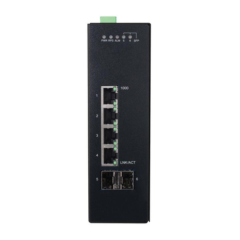
NGI-M05-C1 Front Panel
5 10/100/1000Base-T ports & 1 Gigabit SFP slots
Managed Industrial Ethernet Switch
3.1. Connectors
The Switch utilizes ports with copper and SFP fiber port connectors functioning under
Ethernet/Fast Ethernet/Gigabit Ethernet standards.
10/100/1000Base-T Ports
The 10/100/1000Base-T ports support network speeds of 10Mbps, 100Mbps or 1000Mbps,
and can operate in half- and full-duplex transfer modes. These ports also offer automatic
MDI/MDI-X crossover detection that gives true “plug-and-play” capability – just plug the
network cables into the ports and the ports will adjust according to the end-node devices.
The following are recommended cabling for the RJ45 connectors: (1) 10Mbps – Cat 3 or
better; (2) 100/1000Mbps – Cat 5e or better.
SFP Slots for SFP modules
The four SFP slots are designed to Gigabit SFP modules that support network speed of
1000Mbps.
Installing the SFP modules and Fiber Cable
1. Slide the selected SFP module into the selected SFP slot (Make sure the SFP
module is aligned correctly with the inside of the slot).
2. Insert and slide the module into the SFP slot until it clicks into place.

16
3. Remove any rubber plugs that may be present in the SFP module’s mouth.
4. Align the fiber cable’s connector with the SFP module’s mouth and insert the
connector.
5. Slide the connector in until a click is heard.
6. If you want to pull the connector out, first push down the release clip on top of
the connector to release the connector from the SFP module.
To properly connect fiber cabling:Check that the fiber terminators are clean. You can
clean the cable plugs by wiping them gently with a clean tissue or cotton ball moistened
with a little ethanol. Dirty fiber terminators on fiber optic cables will impair the quality of
the light transmitted through the cable and lead to degraded performance on the port.
Note: When inserting the cable, be sure the tab on the plug clicks into position to ensure
that it is properly seated.
Check the corresponding port LED on the Switch to be sure that the connection is valid.
(Refer to the LED chart).
3.2. Installation
The location chosen for installing the Switch may greatly affect its performance. When
selecting, we recommend considering the following rules:
Install the Switch in an appropriate place. See Technical Specifications for the
acceptable temperature and humidity ranges.
Install the Switch in a location that is not affected by strong electromagnetic field
generators (such as motors), vibration, dust, and direct sunlight.
Leave at least 10cm of space at the front and rear of the unit for ventilation.
ATTENTION
The NGI-M05-C1 Series is an open type device and NGI-M05-C1 Series shall
be DIN-Rail mounted or wall mounted (optional) in cabinet or enclosure.
Hardware Installation
Step 1: Unpack the device and other contents of the package.
Step 2: Fasten DIN-Rail or Wall-mount kit on the rear of the NGI-M05-C1.

17
Connect the 20~57V DC power supply to the PWR & RPS terminal block or 4-pin
power adapter to DC jack receiver on the top of the Switch (Refer to “Wiring
Redundant Power Inputs”).
Step 4: Connect the Ethernet (RJ45) port to the networking device and check the
LED status to confirm the connection is established.
DIN Rail Installation
The NGI-M05-C1 has a DIN rail bracket on the back of the Switch.
Location: The NGI-M05-C1 can be DIN-Rail-mounted in cabinet or enclosure.
Mounting the Switch
Place the NGI-M05-C1 on the DIN rail from above using the slot. Push the front of the
switch toward the mounting surface until it snaps into place with a click sound.

18
Dismounting the Switch
Pull out the lower edge of the switch and then remove the switch from the DIN rail.
Ground the Switch: Before powering on the switch, ground the switch to earth.
Ensure the rack on which the switch is to be mounted is properly grounded and
incompliance with ETSI ETS 300 253. Verify that there is a good electrical connection to
the grounding point on the rack (no paint or isolating surface treatment).
ATTENTION
This product is intended to be mounted to a well-grounded mounting surface
such as a metal panel.
CAUTION
The earth connection must not be removed unless all power supply connection
has been disconnected.
The device is installed in a restricted-access location it has a separate protective
earthing terminal on the chassis that must be permanently connected to earth
ground to adequately ground the chassis and protect the operator from electrical
hazards.
ATTENTION
The product should be mounted in an Industrial Control Panel and the ambient
temperature should not exceed 75°C (167°F).
ATTENTION
A corrosion-free mounting rail is advisable.
When installing, make sure to allow for enough space to properly install the
cabling.
Wiring Power Inputs
You can use either “DC-Jack” or “Terminal Block (PWR)” for primary power and
“Terminal Block (RPS)” for secondary power source, to be a Redundant Power Input.
Top views of DC-Jack and Terminal Block are shown as pictures:
follow the steps below:
Step 1: Insert the positive/negative DC wires into the V+/V- terminal, respectively.

19
Step 2: Use your finger to press the green plug on top of terminal block connector to
insert power cables.
Step 3: Insert the terminal block connector which includes “PWR” and “RPS” into
the terminal block receptor which is located on the top panel.
Option 2: Insert the “DC-Jack” connector into “DC-Jack” receiver and “Terminal
Block (RPS)” into terminal block receptor.
WARNING
Use copper conductors only, 60/75˚C (140/167°F), tighten to 0.56 N•m (5
lb•in).
The wire gauge for the terminal block should range between 12~18 AWG.
Redundant Power Input: You can use “Terminal Block (PWR)” as primary power or
“Terminal Block (PWR)” for redundant power.
Connect power cables to terminal block: Use your finger to press the orange plug on top
of terminal block connector to insert power cables
WARNING
Safety measures should be taken before connecting the power cable.Turn
off the power before connecting modules or wires. The correct power
supply voltage is listed on the product label. Check the voltage of your
power source to make sure that you are using the correct voltage. DO NOT
use a voltage greater than what is specified on the product label. Calculate
the maximum possible current in each power wire and common wire.
Observe all electrical codes dictating the maximum current allowable for
each wire size. If current exceeds the maximum rating, the wiring can
overheat causing serious damage to your equipment.
Please read and follow these guidelines:
•Use separate paths to route wiring for power and devices. If power wiring and
device wiring paths must cross, make sure the wires are perpendicular at the
intersection point.
NOTE: Do not run signal or communications wiring and power wiring through the
same wire conduit. To avoid interference, wires with different signal characteristics
should be routed separately.
•You can use the type of signal transmitted through a wire to determine which wires
should be kept separate. The rule of thumb is that wiring that shares similar
electrical characteristics can be bundled together.
•You should separate input wiring from output wiring.
•We advise that you label the wiring to all devices in the system.

20
Wiring the Alarm Contact:
The Alarm Contact consists of the two last contacts of the terminal block on switch’s top
panel.
ALM: The two last contacts of the 6-contact terminal block connector are used to detect
both power faults and port faults. The two wires attached to the ALM contacts form an
open circuit when:
1. The Switch has lost power from one of the DC power inputs.
OR
2. One of the ports for which the corresponding PORT ALARM DIP Switch is set to ON
is not properly connected.
If neither of these two conditions is satisfied, the Fault circuit will be closed.
WARNING
Use copper conductors only, 60/75˚C (140/167°F), tighten to 0.56 N•m (5
lb•in).
The wire gauge for the terminal block should range between 12~18 AWG.
Powering On the Unit
The Switch accepts the power input voltage from 20~57VDC.
Insert the power cables into the terminal block located on the top of the device.
Check the front-panel LEDs as the device is powered on to verify that the Power
LED is lit. If not, check that the power cable is correctly and securely plugged
in.
Notice: Turn off the power before connecting modules or wires.
-The correct power supply voltage is listed on the product label. Check the
voltage of your power source to make sure that you are using the correct
voltage. Do NOT use a voltage greater than what is specified on the product
label.
-Calculate the maximum possible current in each power wire and common
wire. Observe all electrical codes dictating the maximum current allowable
for each wire size. If current go above the maximum ratings, the wiring
could overheat, causing serious damage to your equipment.
DI Interface Settting:
DI is an interface that adds the ability to input and output digital signals in parallel. Using
a digital input makes it possible to monitor (read) the statuses of the external sensors (i.e
door sensors, water sensors) from remote site.
Reset Button
There has “Reset” button in front of Switch which can help to manually hardware reboot.
Table of contents
Other Tripp Lite Network Router manuals
Popular Network Router manuals by other brands

Nortel
Nortel Contivity 4000 release note

Neoway
Neoway N3800 series user manual

TRENDnet
TRENDnet TW100-BRM504 Quick installation guide

Honeywell
Honeywell RedLINK THM6000R operating manual

Grandstream Networks
Grandstream Networks GWN7062 Quick installation guide

Hirschmann
Hirschmann RS20 series user manual

AddPac
AddPac AP-VR2000 Application note

Zte
Zte VS2801SG user manual

Barracuda Networks
Barracuda Networks NG Firewall F200 / F201 manual

Belkin
Belkin VISION N1 Quick installation guide

Cisco
Cisco 520-T1 - Small Business Pro SR Secure Router Software configuration guide

TeachLogic
TeachLogic AR-960 owner's manual