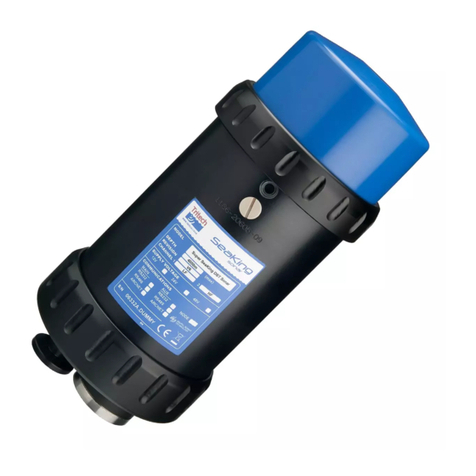
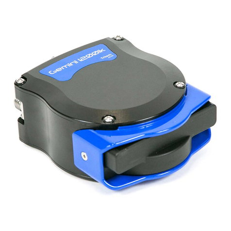
Tritech SeaKing Sidecan User manual

SeaKing Sidecan Sonars
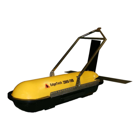
Towfish, SK150 and ROV Sidescan
0374-SOM-00013, Issue: 01

SeaKing Sidecan Sonars SeaKing Sidecan Sonars
0374-SOM-00013, Issue: 01 2© Tritech International Ltd.
© Tritech International Ltd
The copyright in this document is the property of Tritech International Ltd. The document is supplied by Tritech International Ltd on the
understanding that it may not be copied, used, or disclosed to others except as authorised in writing by Tritech International Ltd.
Tritech International Ltd reserves the right to change, modify and update designs and specifications as part of their ongoing product development
programme.
All product names are trademarks of their respective companies.

SeaKing Sidecan Sonars
0374-SOM-00013, Issue: 01 3© Tritech International Ltd.
Table of Contents
Help & Support ........................................................................................................ 5
Warning Symbols ..................................................................................................... 6
1. Introduction .......................................................................................................... 7
I. Specification ......................................................................................................... 8
2. SeaKing ROV Sidescan ............................................................................... 9
2.1. Dimensions of Electronics Pod ........................................................ 9
2.2. Dimensions of Transducers .............................................................. 9
2.3. Physical Properties ............................................................................ 9
2.4. Electrical, Communication & Software .......................................... 10
2.5. Acoustic Properties ......................................................................... 10
3. SeaKing Towfish ....................................................................................... 11
3.1. Dimensions ..................................................................................... 11
3.2. Physical Properties .......................................................................... 11
3.3. Electrical, Communication & Software .......................................... 11
3.4. Acoustic Properties ......................................................................... 12
4. SeaKing Towfish SK150 ........................................................................... 13
4.1. Dimensions ..................................................................................... 13
4.2. Physical Properties .......................................................................... 13
4.3. Electrical, Communication & Software .......................................... 13
4.4. Acoustic Properties ......................................................................... 14
II. Installation ......................................................................................................... 15
5. Installing the ROV Sidescan ..................................................................... 16
5.1. Transducer Orientation ................................................................... 16
5.2. Communications ............................................................................. 17
5.3. Power .............................................................................................. 17
6. Installing the Towfish ................................................................................ 19
6.1. Cable and Strain Relief .................................................................. 19
6.2. Communications ............................................................................. 19
6.3. Power .............................................................................................. 20
7. Installing the SK150 .................................................................................. 21
7.1. Cable and Strain Relief .................................................................. 21
7.2. Communications ............................................................................. 21
7.3. Power .............................................................................................. 22
III. Seanet Pro Software Suite ............................................................................... 23
8. Overview of the Seanet Software Suite .................................................... 24
9. Installing Seanet Pro .................................................................................. 25
10. Seanet Pro ................................................................................................ 26
10.1. Basic Operation ............................................................................ 26
10.2. Settings Bar ................................................................................... 27
10.3. Application Tools ......................................................................... 29
10.4. Dynamic Range and Sonar Rx Indicator ...................................... 33
11. Seanet Dumplog ...................................................................................... 35
11.1. Overview of Process ..................................................................... 35
11.2. Application Window ..................................................................... 35
11.3. Options Dialog .............................................................................. 36
IV. Image Tiler Software ....................................................................................... 39

SeaKing Sidecan Sonars
0374-SOM-00013, Issue: 01 4© Tritech International Ltd.
12. Introduction .............................................................................................. 40
13. Installation ................................................................................................ 41
14. SeaKing Sidescan Image Capture ........................................................... 42
15. Software Functions .................................................................................. 44
15.1. Toolbar .......................................................................................... 44
15.1.1. Project Controls ................................................................. 44
15.1.2. Tile Controls ...................................................................... 46
15.1.3. Zoom .................................................................................. 47
15.1.4. View/Hide Controls ........................................................... 47
15.1.5. Markers .............................................................................. 48
15.1.6. Tile Manipulation .............................................................. 48
15.1.7. Image Export Area ............................................................ 49
15.2. Moving tiles .................................................................................. 50
15.3. Rotating tiles ................................................................................. 50
15.4. Mosaic of Tiles ............................................................................. 51
15.5. Information Dialogs ...................................................................... 52
15.6. Tile List Dialog ............................................................................ 52
15.7. Using Markers .............................................................................. 54
16. Creating the Mosaic Image ..................................................................... 56
16.1. Overview of Process ..................................................................... 56
16.2. Create the Background Chart ....................................................... 57
16.2.1. Image with World File ...................................................... 58
16.2.2. Image with Manual Positional Data .................................. 59
16.2.3. Blank Chart ........................................................................ 60
16.2.4. Co-ordinate System ........................................................... 60
16.3. Add Image Tiles ........................................................................... 61
16.4. Manipulate Image Tiles ................................................................ 61
16.5. Save the Project ............................................................................ 61
16.6. Exporting the completed mosaic as an image .............................. 62
17. Supported File Formats ........................................................................... 64
17.1. For Loading Tiles ......................................................................... 64
17.2. Saving Images or Mosaics ............................................................ 64
17.3. Project Files .................................................................................. 65
17.4. Marker Files .................................................................................. 65
18. Example: Using Sidescan Image Tiles .................................................... 66
V. Service and Maintenance .................................................................................. 68
19. Maintenance ............................................................................................. 69
19.1. After each use of the equipment .................................................. 69
19.2. Regular maintenance .................................................................... 69
19.3. Storage of Equipment ................................................................... 69
19.4. Software Maintenance .................................................................. 70
20. Troubleshooting ............................................................................................... 71
A. ARCNET Termination ...................................................................................... 72
B. CHIRP Signal Processing ................................................................................. 73
C. Networking COMv6 Devices ........................................................................... 75
D. Marker Files ...................................................................................................... 79
Glossary .................................................................................................................. 82

SeaKing Sidecan Sonars
0374-SOM-00013, Issue: 01 5© Tritech International Ltd.
Help & Support
First please read this manual thoroughly (particularly the Troubleshooting section,
if present). If a warranty is applicable, further details can be found in a Warranty
Statement at the end of the manual.
Tritech International Ltd can be contacted as follows:
Mail Tritech International Ltd
Peregrine Road
Westhill Business Park
Westhill, Aberdeenshire
AB32 6JL, UK
Telephone ++44(0)1224 744 111
Fax ++44(0)1224 741 771
Email [email protected]
Website www.tritech.co.uk
Prior to contacting Tritech International Ltd please ensure that the following is
available:
1. The Serial Numbers of the product and any Tritech International Ltd equipment
connected directly or indirectly to it.
2. Software or firmware revision numbers.
3. A clear fault description.
4. Details of any remedial action implemented.
Contamination
If the product has been used in a contaminated or hazardous environment
you must de-contaminate the product and report any hazards prior to
returning the unit for repair. Under no circumstances should a product be
returned that is contaminated with radioactive material.
The name of the organisation which purchased the system is held on record at
Tritech International Ltd and details of new software or hardware packages will be
announced at regular intervals. This manual may not detail every aspect of operation
and for the latest revision of the manual please refer to www.tritech.co.uk
Tritech International Ltd can only undertake to provide software support of systems
loaded with the software in accordance with the instructions given in this manual. It
is the customer's responsibility to ensure the compatibility of any other package they
choose to use.

SeaKing Sidecan Sonars
0374-SOM-00013, Issue: 01 6© Tritech International Ltd.
Warning Symbols
Throughout this manual the following symbols may be used where applicable to
denote any particular hazards or areas which should be given special attention:
Note
This symbol highlights anything which would be of particular interest to
the reader or provides extra information outside of the current topic.
Important
When this is shown there is potential to cause harm to the device
due to static discharge. The components should not be handled without
appropriate protection to prevent such a discharge occurring.
Caution
This highlights areas where extra care is needed to ensure that certain
delicate components are not damaged.
Warning
DANGER OF INJURY TO SELF OR OTHERS
Where this symbol is present there is a serious risk of injury or loss of life.
Care should be taken to follow the instructions correctly and also conduct
a separate Risk Assessment prior to commencing work.

SeaKing Sidecan Sonars
0374-SOM-00013, Issue: 01 7© Tritech International Ltd.
1. Introduction
The SeaKing Sidescan family of sonars provide various methods for obtaining survey
sonar data. The two Towfish and SK150 are both designed to be towed behind a
vessel as it navigates survey lines, while the ROV mounted device is designed to be
fitted to a remotely operated vehicle which is then used to perform the survey.
Electrically and acoustically the devices are very similar, the ROV model is
merely shipped without a hydrodynamic tube and in three components (left/right
transducer and electronics pod). The SK150 is a specially designed Towfish that
can withstand higher pressures found in deeper water. Communication between the
surface computer and the devices can be via RS232, RS485 or ARCNET protocols.
The ROV mounted device can be combined with the Tritech International Ltd Subsea
Junction Box which will allow other devices, such as the SeaKing or Hammerhead
Sonar to be used on the same vehicle.
All three devices are controlled using the Tritech International Ltd Seanet Pro control
and display program and are capable of exporting to a variety of industry standard
formats for use in post-processing survey packages. It is also possible to use the data
in the Tritech International Ltd Sonar Image Tiler program in order to build up a
complete picture of a survey site.

SeaKing Sidecan Sonars
0374-SOM-00013, Issue: 01 8© Tritech International Ltd.
Part I
Specification

SeaKing Sidecan Sonars
0374-SOM-00013, Issue: 01 9© Tritech International Ltd.
2. SeaKing ROV Sidescan
2.1. Dimensions of Electronics Pod
Power & Communications 134
168
Ø110
Ø99
39
Transducer 1 and 2
Not to scale, dimensions in mm.
2.2. Dimensions of Transducers
Not to scale, dimensions in mm.
SIDE VIEW TOP VIEW
side mounting holes
suit M6x1 screw 6.3mm through
34
75
75
32
top mounting holes (x4) to suit M6x1 6.3mm through
counterbored 10mm to 7mm
10
24
46
500
2.3. Physical Properties
Property Electronics Pod Transducers
Weight in air 2.5kg 1.4kg (each)
Weight in water 1.6kg 0.54kg (each)
Depth rating 4000m
Connector Tritech 6-pin waterblock

SeaKing ROV Sidescan SeaKing Sidecan Sonars
0374-SOM-00013, Issue: 01 10 © Tritech International Ltd.
2.4. Electrical, Communication & Software
Power requirement 20 - 36V DC at 12VA
Communication protocols ARCNET, RS232
Communication rates ARCNET: 156kbit·s-1, 78kbit·s-1
RS232: 115.2kBd
Software Tritech Seanet Pro or low level direct command
control
Data log format Tritech V4Log as standard
Export to XTF, TIFF, GeoTIFF and Google Earth
KMZ via converter
2.5. Acoustic Properties
Frequency 325kHz 675kHz
Beamwidth 30° vertical, 1° horizontal 30° vertical, 0.5° horizontal
Maximum range 200m 100m
Pulse length 400μs 200μs
Source level 200dB re 1μPa at 1m
Sensitivity Better than 2μV rms
Gain control 80dB
Dynamic range 40dB (configurable)
Sample rate 5 - 200μs
Data resolution 4 - 8 bits (configurable)
Note
The ROV Sidescan is supplied as either a Low Frequency or High
Frequency sonar and is not switchable.

SeaKing Sidecan Sonars
0374-SOM-00013, Issue: 01 11 © Tritech International Ltd.
3. SeaKing Towfish
3.1. Dimensions
Not to scale, dimensions in mm.
947
Ø63
187
3.2. Physical Properties
Weight in air 7kg
Weight in water 4.1kg
Depth rating 40m
Materials Alumnium body tube and stainless steel nose cone
Operating temperature -10°C to 35°C
Storage temperature -20°C to 50°C
3.3. Electrical, Communication & Software
Power 24V DC at 12VA
Communication ARCNET, RS485 (RS232 optional)
Cable Standard 6.7mm diameter Kevlar re-inforced cable. Supplied
in lengths of 100 and 150 metres.
Software Tritech Seanet Pro
ChesaPeake 'SonarWiz' real-time interface
Low level direct access and control
Data log format Tritech V4Log as standard
Export to XTF, TIFF, GeoTIFF and Google Earth KMZ via
converter

SeaKing Towfish SeaKing Sidecan Sonars
0374-SOM-00013, Issue: 01 12 © Tritech International Ltd.
3.4. Acoustic Properties
Operating frequency 325kHz 675kHz
Beamwidth 30° vertical, 1.7° horizontal 30° vertical, 1° horizontal
Pulse length 400μs 30° vertical, 1° horizontal
Range 200m 100m
Source level 200dB re 1μPa at 1m
Gain control range 80dB
Display
dynamic range
40dB (configurable)
Data resolution 4 - 8 bits (configurable)
Receiver sensitivity Better than 2μV rms
Note
The SeaKing Towfish is supplied as either a High Frequency or Low
Frequency sonar and is not switchable.

SeaKing Sidecan Sonars
0374-SOM-00013, Issue: 01 13 © Tritech International Ltd.
4. SeaKing Towfish SK150
4.1. Dimensions
Not to scale, dimensions in mm.
1160
Ø124
10° 385
4.2. Physical Properties
Weight in air 25.5kg
Weight in water 15.5kg
Depth rating 120m
Materials Polyester powder coated aluminium
Operating temperature -10 to 35°C
Storage temperature -20 to 50°C
Maximum towing speed 5 knots
4.3. Electrical, Communication & Software
Power requirement 36 - 48V DC (300mA at 36V)
Connector Tritech standard 6-pin waterblock
Cable Wire armoured
Software Tritech Seanet Pro or low level direct access and control
Data log format Tritech V4Log as standard
Export to XTF, TIFF, GeoTIFF and Google Earth KMZ
via converter

SeaKing Towfish SK150 SeaKing Sidecan Sonars
0374-SOM-00013, Issue: 01 14 © Tritech International Ltd.
4.4. Acoustic Properties
Operating frequency 150kHz
Beamwidth 60° vertical, 1.4° horizontal
Maximum range 350m
Minimum range 0.4m
Range resolution 5 - 300mm
Source level 210dB re 1μPa at 1m
Pulse length 400μs
Bandwidth 40kHz

SeaKing Sidecan Sonars
0374-SOM-00013, Issue: 01 15 © Tritech International Ltd.
Part II
Installation

SeaKing Sidecan Sonars
0374-SOM-00013, Issue: 01 16 © Tritech International Ltd.
5. Installing the ROV Sidescan
5.1. Transducer Orientation
Caution
Although the sonar is rugged, it should be handled with care, particularly
the connector and transducers.
The SeaKing ROV Sidescan sonar comprises two separate transducers which are
connected wit interconnect leads to a dual channel electronics pod.
25°
ROV
Figure 5.1. ROV Sidescan Installation Example
The transducers should be mounted at an ideal tilt angle of 25° below horizontal as
indicated in Figure 5.1, “ROV Sidescan Installation Example”. This will reduce the
length of the blind spot directly below and to each side of the vehicle (i.e., the areas
which do not fall within the transmit beam coverage). With a 25° angle the ROV can
be flown at a height of approximately 10% of the configured range.
To increase the maximum range the angle can be reduced to 10° and the ROV height
above the seabed increased but doing so will increase the size of the blind area
underneath the ROV. Targets may be missed if the ROV is flown directly over the
top of them.
A guard can be fitted to the ROV to protect from impact damage but this must not
overlap the transducer area or it may have an effect on the sonar image.
The electronics pod should be secured by clamping on the cylindrical body. The
clamp should be applied centrally to the aluminium body tube and should not be
over-tightened. Any metallic clamps should be electrically insulated from the body
by means of rubber or plastic strips or mount brackets of at least 3mm thickness and
extending at least 3mm beyond the clamp boundary to reduce any galvanic corrosion
effect. Non-metallic clamps are preferable and if metallic clamps are used they should
be painted or lacquered with at least two or three coatings.
Caution
Avoid any metal alloys containing copper such as brass or bronze.

Installing the ROV Sidescan SeaKing Sidecan Sonars
0374-SOM-00013, Issue: 01 17 © Tritech International Ltd.
Note
The electronics pod does not need to be installed in a dry area and is rated
against water ingress so can be placed anywhere on the ROV.
5.2. Communications
The SeaKing ROV Sidescan electronics pod is fitted with a maximum of four standard
Tritech waterblock connectors. Two of these will be labelled PORT and STARBOARD
and these should be used to connect to the transducers using a cable that is wired
straight through (with a 1 to 1 wiring). The other two ports are MAIN which is
for connection to the surface and optionally AUX which is for connecting auxiliary
devices such as altimeters, oceanographic sensors and scanning sonars. The AUX port
may be blanked off.
The MAIN connector and optional AUX connector are wired as follows:
Tritech Waterblock
Pin Function Cable colour
1ARCNET A
RS232 TX Yellow
2ARCNET B
RS232 RX Blue
3 DC + Red
4 DC - Black
5 RS232 Ground Green
6 Earth/cable shield cable screen
Note
If communicating using the ARCNET protocol it will be necessary to have
resistors fitted at each end of the cable. For more details please refer to
Appendix A, ARCNET Termination for more information.
5.3. Power
The SeaKing Towfish range of sensors are designed to work over a smoothed DC
power supply over the range specified in Chapter 2, SeaKing ROV Sidescan.
Caution
Never try to make the Towfish work over a longer cable by increasing
the voltage above the maximum specified, doing so may cause permanent
damage.

Installing the ROV Sidescan SeaKing Sidecan Sonars
0374-SOM-00013, Issue: 01 18 © Tritech International Ltd.
If using a rectified transformer PSU the output must have a filter capacitor of at least
470μF for each head that is being powered. The use of unregulated power supplies
is not recommended.
If powering the head down a long lead or umbilical, the maximum recommended
loop resistance of the power line must not exceed 10Ω for a single device. If other
SeaKing devices are connected via the AUX port in a network then the loop resistance
should be 5Ω for two devices and 3Ω for three devices.
If the supply voltage is less than the minimum specified in Chapter 2, SeaKing ROV
Sidescan the Sidescan is unlikely to work correctly.
Ground Fault Monitoring Equipment
The power supply within all SeaKing devices includes an electrically
isolated DC to DC converter front end with a small capacitive connection
made to the sonar chassis. This should not noticeably affect any impressed
current Ground Fault Interrupter (GFI) or Residual Current Devices
(RCD).

SeaKing Sidecan Sonars
0374-SOM-00013, Issue: 01 19 © Tritech International Ltd.
6. Installing the Towfish
Note
The Towfish is supplied balanced for level flight in water. Do not add to
or alter the parts as this may affect the hydrodynamic properties.
6.1. Cable and Strain Relief
Note
In order to have enough cable it is advisable to have at least 3m of cable for
every 1m of operating depth. The cable should be re-inforced with Kevlar.
The SeaKing Towfish is fitted with a strain relief mechanism which is located in the
tow arm by two cable clamps and attached by wire to the rear section. A side plate
is fitted on the tow arm to secure the cable and strain relief in place. The tow arm
is connected to the tow bar on the body using a pivot assembly and pivot pin which
is designed to shear if the Towfish is subject to impact whilst under way. This will
enable the Towfish to be recovered tail first and should prevent it from becoming
entangled.
An acetal tail cone is screwed on the rear end which can be unscrewed to enable the
removal of the safety wire and pin assembly.
If the fins hit a hard object they are designed to slide out and are secured by an elastic
cord which prevents them from being lost. This elastic cord has a loop in one end
and the safety wire should be passed through this loop before being secured with the
tail cone and pin assembly.
6.2. Communications
The SeaKing Towfish is fitted with a standard Tritech waterblock connector. This is
a 6 pin connector and is wired as follows:

Installing the Towfish SeaKing Sidecan Sonars
0374-SOM-00013, Issue: 01 20 © Tritech International Ltd.
Tritech Waterblock
Pin Function Cable colour
1ARCNET A
RS232 TX Yellow
2ARCNET B
RS232 RX Blue
3 DC + Red
4 DC - Black
5 RS232 Ground Green
6 Earth/cable shield cable screen
Note
If communicating using the ARCNET protocol it will be necessary to have
resistors fitted at each end of the cable. For more details please refer to
Appendix A, ARCNET Termination for more information.
6.3. Power
The SeaKing Towfish range of sensors are designed to work over a smoothed DC
power supply over the range specified in Chapter 3, SeaKing Towfish.
Caution
Never try to make the Towfish work over a longer cable by increasing
the voltage above the maximum specified, doing so may cause permanent
damage.
If using a rectified transformer PSU the output must have a filter capacitor of at least
470μF for each head that is being powered. The use of unregulated power supplies
is not recommended.
If powering the head down a long lead or umbilical, the maximum recommended
loop resistance of the power line must not exceed 10Ω.
If the supply voltage is less than the minimum specified in Chapter 3, SeaKing
Towfish the Towfish is unlikely to work correctly.
Ground Fault Monitoring Equipment
The power supply within all SeaKing devices includes an electrically
isolated DC to DC converter front end with a small capacitive connection
made to the sonar chassis. This should not noticeably affect any impressed
current Ground Fault Interrupter (GFI) or Residual Current Devices
(RCD).
This manual suits for next models
5
Table of contents
Other Tritech Sonar manuals
Popular Sonar manuals by other brands
Kongsberg
Kongsberg Simrad SU90 Series manual
Lowrance
Lowrance ActiveTarget installation manual

Lowrance
Lowrance X-28 Installation and operation instructions
Klein
Klein 5000 SERIES Operation and maintenance manual

Interphase
Interphase PC/180 troubleshooting guide

Eagle
Eagle FishMark 500C Installation and operation instructions
