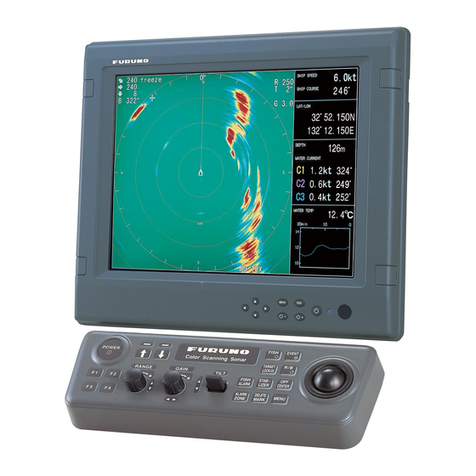
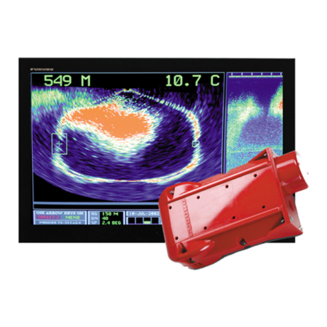
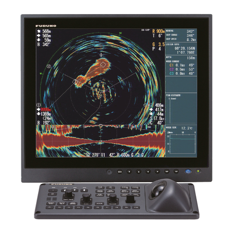
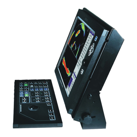
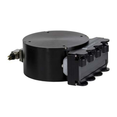
Furuno FSV25S User manual

COLOR SCANNING
SONAR
FSV-25/FSV-25S
OPERATOR'S MANUAL
www.furuno.com
Model

The paper used in this manual
is elemental chlorine free.
・FURUNO Authorized Distributor/Dealer
9 52 Ashihara cho,
Nishinomiya, 662 8580, JAPAN
A
:
MAY
2014
Printed in Japan
All rights reserved.
A1
:
AUG
.
08, 2014
Pub. No.
OME-13440-A1
(
ETMI
)
FSV-25 25S
0 0 0 1 7 8 7 6 9 1 0

i
IMPORTANT NOTICES
General
• This manual has been authored with simplified grammar, to meet the needs of international us-
ers.
• The operator of this equipment must read and follow the descriptions in this manual. Wrong op-
eration or maintenance can cancel the warranty or cause injury.
• Do not copy any part of this manual without written permission from FURUNO.
• If this manual is lost or worn, contact your dealer about replacement.
• The contents of this manual and equipment specifications can change without notice.
• The example screens (or illustrations) shown in this manual can be different from the screens
you see on your display. The screens you see depend on your system configuration and equip-
ment settings.
• Save this manual for future reference.
• Any modification of the equipment (including software) by persons not authorized by FURUNO
will cancel the warranty.
• All brand and product names are trademarks, registered trademarks or service marks of their
respective holders.
How to discard this product
Discard this product according to local regulations for the disposal of industrial waste. For disposal
in the USA, see the homepage of the Electronics Industries Alliance (http://www.eiae.org/) for the
correct method of disposal.
How to discard a used battery
Some FURUNO products have a battery(ies). To see if your product has a battery, see the chapter
on Maintenance. Follow the instructions below if a battery is used. Tape the + and - terminals of
battery before disposal to prevent fire, heat generation caused by short circuit.
In the European Union
The crossed-out trash can symbol indicates that all types of batteries
must not be discarded in standard trash, or at a trash site. Take the
used batteries to a battery collection site according to your national
legislation and the Batteries Directive 2006/66/EU.
In the USA
The Mobius loop symbol (three chasing arrows) indicates that Ni-Cd
and lead-acid rechargeable batteries must be recycled. Take the used
batteries to a battery collection site according to local laws.
In the other countries
There are no international standards for the battery recycle symbol. The number of symbols can
increase when the other countries make their own recycle symbols in the future.
Cd
PbNi-Cd

ii
SAFETY INSTRUCTIONS
Do not open the equipment.
Only qualified personnel are allowed to
work inside the equipment.
Do not disassemble or modify the
equipment.
Fire, electrical shock or serious injury can
result.
Do not operate the equipment with
wet hands.
Electrical shock may result.
Do not install the equipment where it
may be subject to rain or water splash.
Fire or electrical shock can result if water
leaks in the equipment.
WARNING
Indicates a potentially hazardous situation which, if not avoided,
could result in death or serious injury.
CAUTION
Indicates a potentially hazardous situation which, if not avoided,
may result in minor or moderate injury.
Warning, Caution Mandatory Action
Prohibitive Action
WARNING
WARNING
DANGER
DANGER
Indicates a hazardous situation which, if not avoided, will result in
death or serious injury.
The operator of this equipment must read the safety instructions before attempting to operate
the equipment.
Keep away from raise/lower
shaft in hull unit when the
shaft is moving.
Gears in hull unit will cause
serious injury.
Immediately turn off the power at the
switchboard if water leaks into the
equipment or something is dropped
into the equipment.
Continued use of the equipment can
cause fire or electrical shock. Contact a
FURUNO agent for service.
Immediately turn off the power at the
switchboard if the equipment is
emitting smoke or fire.
Continued use of the equipment can
cause fire or electrical shock. Contact a
FURUNO agent for service.
Do no place liquid-filled containers on
the equipment.
Fire or electrical shock can result if
something spills into the equipment.
Turn off the power immediately
if water leaks into the equipment or
something is dropped into the equip-
ment.
Fire or electrical shock can result if the
power is not turned off.
Use the correct fuse.
Fire or bodily injury can result if the
wrong fuse is used.

SAFETY INSTRUCTIONS
iii
CAUTION
CAUTION
Maximum speed while the transducer is
projected or being raised or lowered
is as below, to prevent damage to the
transducer.
WARNING
Before raising or lowering the trans-
ducer manually, make sure the motor
brake and drive shaft brake are engaged.
Handle the transducer carefully.
Do not swing the transducer or strike it
against an object, to prevent damage to the
transducer.
Do not transmit the transducer when it
is out of water (for example, when dry-
docked), to prevent damage to the
transducer.
Do not remove the brake on the hull
unit, to keep the shaft from falling.
Replace anti-corrosion zinc plates yearly.
Corrosion between the main shaft and
transducer may result if not replaced,
allowing water leakage and/or loss of
transducer.
An LCD is made of glass. Rough handling
can break the glass.
Handle the LCD carefully to prevent injury.
WARNING LABELS
Warning labels are attached to the units of the system.
Do not remove the labels.
If a label is missing or damaged, contact a FURUNO
agent or dealer about replacement.
Name: Warning Label
Type: 10-079-7-6144
Code No.: 100-310-880-10
Name: Warning Label
Type: 10-089-5548-1
Code No.: 100-386-951-10
Name: Warning Label (1)
Type: 86-003-1011-3
Code No.: 100-236-233-10
Name: Warning Label
Type: 10-071-5313
Code No.: 100-291-160-10
Name: Danger Label
Type: 10-089-7544-0
Code No.: 100-394-370-10
Less than 1100
Projected length (mm)
1100 to 1300
Over 1300
Transducer
stopped
Raising/
Lowering
20.0
18.0
16.0
Max. speed (kn)
14.5
13.5
12.0

iv
EMERGENCY STOP BUTTON ON
HULL UNIT
The EMERGENCY STOP button on the hull unit stops the raising or lowering of the transducer in
case of an emergency. The transducer stops moving when the button is operated, a warning mes-
sage appears and the transducer cannot be raised or lowered. The transducer is also stopped
when the ratchet wrench in the hull unit, which is used to manually raise the transducer, is re-
moved from its holder.
To release the emergency stop condition, first confirm that no one is near the hull unit. Then do
the following:
• To release the EMERGENCY STOP button, turn the button in the direction of the arrow on the
button.
• Return the ratchet wrench to its holder.
EMERGENCY STOP button
(default position)

v
TABLE OF CONTENTS
FOREWORD................................................................................................................... ix
SYSTEM CONFIGURATION .......................................................................................... xi
1. OPERATIONAL OVERVIEW................................................................................. 1-1
1.1 Control Description .....................................................................................................1-1
1.1.1 Control unit .....................................................................................................1-1
1.1.2 Sub control unit (option) .................................................................................1-3
1.1.3 Remote controller (option)..............................................................................1-4
1.2 Breaker On/Off ...........................................................................................................1-4
1.3 Turning the Power On/Off...........................................................................................1-5
1.4 Lowering, Raising the Transducer..............................................................................1-6
1.4.1 Lowering the transducer.................................................................................1-6
1.4.2 Raising the transducer ...................................................................................1-7
1.4.3 How to check how far the transducer is projecting.........................................1-7
1.5 Screen Brilliance, Panel Dimmer................................................................................1-8
1.5.1 Screen brilliance.............................................................................................1-8
1.5.2 Panel dimmer .................................................................................................1-8
1.6 Display Mode, Display Division ................................................................................1-10
1.6.1 How to select a display mode.......................................................................1-11
1.6.2 Display mode picture examples ...................................................................1-11
1.7 Software Function Key .............................................................................................1-13
1.8 How to Adjust the Gain.............................................................................................1-14
1.9 How to Use the Menu...............................................................................................1-15
2. HORIZONTAL MODE ............................................................................................2-1
2.1 Basic Operating Procedure ........................................................................................2-1
2.2 Indications and Markers .............................................................................................2-2
2.2.1 Horizontal mode, full-screen display ..............................................................2-2
2.2.2 Horizontal2 mode ...........................................................................................2-3
2.3 Display Range ............................................................................................................2-4
2.4 Tilt Angle.....................................................................................................................2-5
2.4.1 How to set the tilt angle ..................................................................................2-5
2.4.2 Automatic tilt...................................................................................................2-6
2.4.3 Relation between bottom echo and tilt angle .................................................2-7
2.4.4 Tilt angle for surface fish ................................................................................2-8
2.4.5 Suitable tilt angle ............................................................................................2-8
2.5 How to Measure Range and Bearing to a Target .......................................................2-9
2.6 How to Eliminate Weak Echoes .................................................................................2-9
2.6.1 Change sensitivity of TVG curve ....................................................................2-9
2.6.2 Change near gain, far gain...........................................................................2-10
2.7 How to Adjust Strong, Weak Echoes........................................................................2-11
2.7.1 AGC..............................................................................................................2-11
2.7.2 How to shorten pulse length.........................................................................2-11
2.7.3 How to suppress unwanted echoes .............................................................2-12
2.8 How to Suppress Bottom and Sea Surface Reflections in Shallow Waters .............2-12
2.9 How to Reject Sonar Interference and Noise ...........................................................2-13
2.9.1 How to identify the noise source ..................................................................2-13
2.9.2 Change TX interval.......................................................................................2-13
2.9.3 Interference rejector .....................................................................................2-14
2.9.4 Shift TX frequency........................................................................................2-14
2.9.5 Noise limiter..................................................................................................2-15
2.9.6 Reverberation...............................................................................................2-16

TABLE OF CONTENTS
vi
2.9.7 Echo average ............................................................................................... 2-16
2.10 How to Adjust Beamwidth ........................................................................................ 2-16
2.11 How to Track a School of Fish ................................................................................. 2-17
2.11.1 How to select the target lock mode.............................................................. 2-17
2.11.2 Fish mode .................................................................................................... 2-18
2.11.3 Target mark mode........................................................................................ 2-19
2.11.4 Target lock menu description....................................................................... 2-19
2.12 Presentation Mode ................................................................................................... 2-20
2.12.1 Presentation mode description..................................................................... 2-20
2.12.2 How to select a presentation mode.............................................................. 2-21
2.13 How to Detect Schools of Fish Aurally ..................................................................... 2-21
2.13.1 How to set the bearing ................................................................................. 2-21
2.13.2 How to select the audio sector..................................................................... 2-22
2.13.3 Automatic training ........................................................................................ 2-23
2.13.4 Reverberation for audio signal ..................................................................... 2-23
2.14 Fish Alarm ................................................................................................................ 2-23
2.14.1 How to set the fish alarm.............................................................................. 2-23
2.14.2 How to set the fish alarm level ..................................................................... 2-25
2.15 How to Relocate a School of Fish ............................................................................ 2-26
2.16 How to Compare Concentration of School of Fish................................................... 2-26
2.16.1 How to compare with the fish estimate mark ............................................... 2-26
2.16.2 How to compare with the circle cursor ......................................................... 2-28
2.17 How to Measure the Speed of a School of Fish....................................................... 2-29
2.17.1 How to measure the speed of a school of fish ............................................. 2-29
2.17.2 How to delete fish marks.............................................................................. 2-30
2.18 Event Mark, Own Ship Position Mark....................................................................... 2-31
2.18.1 How to enter an event mark......................................................................... 2-31
2.18.2 How to enter an own ship position mark ...................................................... 2-32
2.18.3 How to erase an event mark, own ship position mark.................................. 2-32
2.19 Net Course Mark ...................................................................................................... 2-33
2.20 Net Behavior ............................................................................................................ 2-34
2.21 Other Menu Items .................................................................................................... 2-35
2.21.1 Display Setting menu ................................................................................... 2-35
2.22 How to Interpret the Horizontal Display.................................................................... 2-39
2.22.1 Bottom and school of fish echoes ................................................................ 2-39
2.22.2 Unnecessary echoes.................................................................................... 2-41
3. VERTICAL MODE ..................................................................................................3-1
3.1 Basic Operating Procedure........................................................................................ 3-1
3.2 How the Vertical Mode Works.................................................................................... 3-2
3.2.1 Overview ........................................................................................................ 3-2
3.2.2 How to set the vertical display........................................................................ 3-2
3.3 Vertical Indications and Marks ................................................................................... 3-3
3.3.1 Typical vertical display ................................................................................... 3-3
3.3.2 Vertical bearing mark, tilt mark....................................................................... 3-4
3.3.3 Cursor position reference mark...................................................................... 3-5
3.4 Auto Train...................................................................................................................3-5
3.5 Display Range............................................................................................................ 3-6
3.6 How to Measure the Range, Bearing to a Target....................................................... 3-6
3.7 How to Eliminate Weak Echoes ................................................................................. 3-7
3.7.1 Change sensitivity of TVG curve.................................................................... 3-7
3.7.2 Change near gain, far gain............................................................................. 3-8
3.8 How to Adjust Strong, Weak Echoes ......................................................................... 3-8
3.8.1 AGC ............................................................................................................... 3-8
3.8.2 How to shorten pulse length........................................................................... 3-9
3.8.3 How to suppress unwanted echoes ............................................................... 3-9

TABLE OF CONTENTS
vii
3.9 How to Reject Sonar Interference and Noise ...........................................................3-10
3.9.1 How to identify the noise source ..................................................................3-10
3.9.2 Interference rejector .....................................................................................3-10
3.9.3 Shift TX frequency........................................................................................3-10
3.9.4 Noise limiter..................................................................................................3-11
3.9.5 Reverberation...............................................................................................3-12
3.9.6 Echo average ...............................................................................................3-12
3.10 How to Adjust Beam Width.......................................................................................3-12
3.11 Other Menu Items.....................................................................................................3-13
4. NUMERIC/GRAPHIC DATA DISPLAY .................................................................4-1
4.1 Numeric/Graphic Data Display ...................................................................................4-1
4.2 Numeric, Graphic Data Description............................................................................4-2
5. HOW TO CUSTOMIZE THE SONAR ....................................................................5-1
5.1 User Menu..................................................................................................................5-1
5.1.1 How to program the user menu......................................................................5-1
5.1.2 How to remove items from the user menu .....................................................5-2
5.2 Function Keys (F1 to F10) ..........................................................................................5-3
5.2.1 How to execute a program .............................................................................5-3
5.2.2 How to program the function keys..................................................................5-3
5.2.3 How to check function key programs .............................................................5-4
5.2.4 How to erase programs ..................................................................................5-5
5.2.5 How to program the function keys of remote controller..................................5-6
5.3 USER PROG Control .................................................................................................5-6
5.3.1 How to select a user program ........................................................................5-6
5.3.2 How to program the USER PROG control .....................................................5-7
6. OTHERS MENU.....................................................................................................6-1
6.1 Erase Marks Menu .....................................................................................................6-1
6.2 Wheel Setting Menu ...................................................................................................6-2
6.3 Display Setting Menu..................................................................................................6-3
6.4 Alarm & Audio Menu...................................................................................................6-5
6.5 Register Menu ............................................................................................................6-6
6.6 Initial Setting Menu .....................................................................................................6-7
7. RECORD/RECALL OPERATION..........................................................................7-1
7.1 How to Specify Where to Save Still Images ...............................................................7-1
7.2 How to Save Still Images............................................................................................7-2
7.3 How to Display Saved Still Images.............................................................................7-3
7.3.1 How to display the latest still image ...............................................................7-3
7.3.2 How to display a still image from the file list...................................................7-4
7.4 How to Save Motion Images.......................................................................................7-4
7.5 How to Play Back Motion Images...............................................................................7-5
7.6 How to Save Setting Data ..........................................................................................7-6
7.7 How to Load Saved Data............................................................................................7-7
7.7.1 How to load the setting information ................................................................7-7
7.7.2 How to replay setting information ...................................................................7-8
7.8 How to Delete Files ....................................................................................................7-9
8. MAINTENANCE, TROUBLESHOOTING ..............................................................8-1
8.1 Preventive Maintenance.............................................................................................8-1
8.2 Hull Unit Maintenance ................................................................................................8-2
8.2.1 How to grease parts .......................................................................................8-3
8.2.2 How to replace the gasket..............................................................................8-3
8.2.3 How to replace the anti-corrosion zinc plates.................................................8-4

TABLE OF CONTENTS
viii
8.3 How to Replace Fuses ............................................................................................... 8-5
8.4 Battery on the Mother Board...................................................................................... 8-5
8.5 How to Clean the Filter............................................................................................... 8-6
8.6 How to Clean the Trackball in the Control Unit .......................................................... 8-6
8.7 Troubleshooting ......................................................................................................... 8-7
8.8 Warning Messages .................................................................................................... 8-8
8.9 Error Codes.............................................................................................................. 8-10
8.10 Status Messages...................................................................................................... 8-10
8.11 Tests ........................................................................................................................ 8-11
8.11.1 How to display the Test menu...................................................................... 8-11
8.11.2 Operation test............................................................................................... 8-12
8.11.3 Board test..................................................................................................... 8-13
8.11.4 Panel test ..................................................................................................... 8-14
8.11.5 Test pattern.................................................................................................. 8-15
8.11.6 Fan monitor test ........................................................................................... 8-15
8.12 How to Raise the Transducer from the Hull Unit...................................................... 8-16
8.12.1 How to raise the transducer automatically ................................................... 8-16
8.12.2 How to raise the transducer manually.......................................................... 8-18
8.13 How to Check the Brake in the Hull Unit .................................................................. 8-19
8.13.1 How to check the brake in the raise/lower control box................................. 8-19
8.13.2 How to measure the gap in the motor brake................................................ 8-20
8.13.3 How to measure the gap in the drive shaft gear .......................................... 8-23
APPENDIX 1 MENU TREE .......................................................................................AP-1
SPECIFICATIONS .....................................................................................................SP-1
INDEX.......................................................................................................................... IN-1

ix
FOREWORD
A Word to the Owner of the FSV-25/FSV-25S
Congratulations on your choice of the FURUNO FSV-25/FSV-25S Color Scanning Sonar. We are
confident you will see why the FURUNO name has become synonymous with quality and reliabil-
ity.
Since 1948, FURUNO Electric Company has enjoyed an enviable reputation for quality marine
electronics equipment. This dedication to excellence is furthered by our extensive global network
of agents and dealers.
This equipment is designed and constructed to meet the rigorous demands of the marine environ-
ment. However, no machine can perform its intended function unless operated and maintained
properly. Please carefully read and follow the recommended procedures for operation and main-
tenance.
Thank you for considering and purchasing FURUNO equipment.
Features
The FSV-25/FSV-25S is a full-circle, multibeam electronic color scanning sonar which detects and
displays schools of fish on the monitor of your choice.
The main features of the FSV-25/FSV-25S are
• Menu-driven operation.
• Vivid 32-color echo strength dependent display for improved recognition of bottom, fish school
concentration, distribution and volume.
• Dual Display mode
• Schools of fish can be searched from horizontal (range direction), vertical (depth direction) with
vertical features.
• Pitching and rolling compensation for stable picture always.
• User programs for one-touch setup of equipment.
• Function keys for direct access to desired menu item.
• Storage and replay of picture and settings.
• Wide variety of display combination modes: horizontal and vertical.
• Various marks and alphanumeric fishing and navigation information for intuitive operation.
• Fish histogram shows signal strength distribution of echo within estimate mark.
• Audio function for monitoring echoes along user-selected area through loudspeaker (option).
• Fish mark estimates fish speed.
• Fish estimate feature to compare the volume of two schools of fish.
• Net course mark shows probable drift of net against tidal current.

FOREWORD
x
About this manual
• This manual describes the functions of the FSV-25 and FSV-25S. The main difference between
the two models is the range:
• FSV-25: 60 m to 5000 m
• FSV-25S: 60 m to 10000 m
• Unless noted otherwise, “click” means to push the left button.

xi
SYSTEM CONFIGURATION
Standard configuration is shown with solid lines. Dashed lines indicate optional or local supply
equipment.
MAINSW
MAINSW
FUSE
FUSE
200-220 VAC,
3ø, 50/60 Hz
External
monitor
External
monitor
Processor unit
FSV-2503 (FSV-25)
FSV-2503S (FSV-25S)
External USB devices
(mouse, HDD)
NMEA IEC 61162-1 device
Junction box FI-5002
External speaker
Sub control unit
FSV-853
Control unit
FSV-2501
Remote controller
FSV-2504
Remote controller
FSV-2504
Hull unit
FSV-253/254
Raise/Lower
control box*
FSV-2530
Junction box
FSV-2550
12-24 VDC
Rectifier unit
RU-1746B-2
100/110/115/
220/230 VAC
1ø, 50/60 Hz
100/110/115/
220/230 VAC
1ø, 50/60 Hz
Interface unit
FSV-8502
Transceiver unit
FSV-251
Power supply
unit
FSV-252
* The distance between the Raise/Lower control box and the
Huill unit can be extended with the optional Control box
extension box FSV-2560.

SYSTEM CONFIGURATION
xii
This page is intentionally left blank.

1-1
1. OPERATIONAL OVERVIEW
1.1 Control Description
1.1.1 Control unit
Key Function
Turns power on.
Turns power off.
Raises the transducer.
If the mid protrusion key is programmed to [Fixed Position]: The transduc-
er goes to the mid protrusion position.
If the mid protrusion key is programmed to [Any Position]: The transducer
stops at desired position.
Lowers the transducer (full protrusion).
Enters the net shooting mark or own ship mark.
Sets vertical cross section bearing.
Automatic transducer train width on audio bearing mark (horizontal mode), ver-
tical bearing mark (vertical mode).
Off centers own ship’s position (horizontal mode).
• Displays range and bearing marks (horizontal mode).
• Sets the audio bearing.
Deletes trackball-selected mark.
DOWN/STOP
Trackball Trackball unit
Scrollwheel
Function keys
Tilt lever
Left button
Left button
Right button
Right button
Speaker
DOWN/STOP
SHOOT
V1/S
V2
AUTO
TRAIN
OFF
CENTER
R/B
AUDIO
DELETE
MARK

1. OPERATIONAL OVERVIEW
1-2
Enters event mark 1 or own ship mark (horizontal mode).
Enters event mark 2 or own ship mark (horizontal mode).
Turns the estimate mark on/off (horizontal mode).
Enters target lock mark (horizontal mode).
Enters fish mark (horizontal mode).
Short-push: Opens or closes the menu; returns to the previous menu.
Long-push: Closes all menus.
Sets auto tilt angle.
Selects display mode.
• Selects the mode tab on the menu.
• Selects mode to adjust sensitivity, select range, set tilt, and user program
number.
Execute assigned program.
Selects user-programmed settings.
Adjusts gain for horizontal vertical scans.
Selects the display range for horizontal and vertical scans.
Sets transducer tilt angle for horizontal scans.
Key Function
EVENT
EVENT
1
ESTI-
MATE
ESTI-
MATE 2
TARGET
LOCK
FISH
MENU/
ESC
AUTO
TILT
DISP
MODE
H/V/S
110
~
USER PROG
GAIN
RANGE

1. OPERATIONAL OVERVIEW
1-3
1.1.2 Sub control unit (option)
The sub control unit lets you control the sonar from a remote location.
Note: Before connecting a sub control unit, turn off the power from the main control
unit.
Trackball
unit
Trackball:
• Positions cursor.
• Selects items, options on menu.
Left button:*1
• Confirms the selected item.
• Selects the item to drag and drop.*2
• Enters fish mark (default function).*3
Scrollwheel:
• Rotate: Sets numeric data; selects menu item; sets tilt angle, range, bear-
ing/train angle, gain, and user program number
• Push: Confirms the selected item; shows the [Select Mark] window.
Right button:*1
• Shows pop-up menu.
• Confirms the selected item.
• Enters event mark 1.*3
*1 “Left click”, “right click” means “push the left button”, “push the right button”,
respectively.
*2 “Drag and drop” means to hold down the left button while dragging the cursor
and releasing the button at desired “drop point”.
*3 The right button or left button can be programmed to enter the marks listed
below. Further, those buttons can erase the marks listed below. For details,
contact your dealer.
• Event mark 1, event mark 2
• Fish mark
• Fish volume mark 1, fish volume mark 2
Speaker Sounds buzzer; monitors echoes aurally.
No. Function (on control unit)
1 Same as F1, F2, F3 and F4 key.
(The program can be changed.
See paragraph 5.2.2.)
2 Same as trackball unit on con-
trol unit.
Key Function
2
1

1. OPERATIONAL OVERVIEW
1-4
1.1.3 Remote controller (option)
The remote controller lets you control the sonar from a remote location.
Note: Keep the remote controller away from water and water splash. Hook the remote
controller to the bracket when it is not in use.
1.2 Breaker On/Off
The power supply unit, transceiver unit and hull unit have a breaker. Turn them on
from the switchboard or breaker.
Note 1: Turn on the breaker of the power supply unit before turning on the breaker of
the transceiver unit. The transceiver unit may be damaged if it is powered first and its
tap connection is wrong.
Note 2: If the breaker on the hull unit is turned on after the transducer is raised or low-
ered from the control unit, beware of the moving hull unit.
No. Function (on control unit)
1 Same as F1, F2 and F3 key.
2Same as key.
3 Same as right button.
4 Same as the left button.
5Same as EVENT, ESTIMATE,
TARGET LOCK and FISH keys.
6 Same as trackball.
7 Same as OFF CENTER key.
8 Same as USER PROG control.
9 Same as GAIN control.
10 Same as RANGE control.
11 Same as SHOOT key.
12 Records the current picture.
13 Shows the still image window.
14 Same as DISP MODE key.
15 Same as AUTO TRAIN key.
16 Same as V1/S, V2 key.
17 Same as AUTO TILT key.
18 Same as TILT lever.
19 Same as H/V/S key.
䌆䋱 䌆䋲 䌆䋳
1 2
1
2
3
4
6
5
78
9
10 12
11
13
14
15
16
17
18
19
12345
AUTO
AUTO
H/V/S
DISP
MODE
RECALL
MEMO
SHOOT
OFF-
CENT
DOWN/STOP
, 䇭㩷,
DOWN/STOP

1. OPERATIONAL OVERVIEW
1-5
1.3 Turning the Power On/Off
Turning the power on
Press the POWER ON (|) switch. A beep sounds, and the display changes in the fol-
lowing sequence: FURUNO display →model display →operation test display (see
section 8.11.2). Then the lamp above the switch changes as below. The last-used
mode is activated in approximately 140 seconds after turning the power on.
The transducer is not automatically retracted at start up. After applying the power con-
firm that the transducer is retracted. If the transducer is retracted the lamp above the
key is on steadily. If the power goes off by power failure, etc. use the key to
retract the transducer and then operate the system.
Turning the power off
1. First retract the transducer with the key. The lamp above the key blinks
while the transducer is being raised and lights steadily when it is fully raised.
Note: While raising the transducer, the ship speed must be not exceed the limits
posted below, to prevent damage to the transducer and hull unit.
- projected length not more than 1100 mm: 14.5 kn
- projected length 1100 mm - 1300 mm: 13.5 kn
- projected length Over 1300: 12 kn
2. After the key lights steadily, press the POWER OFF ( ) switch until the
screen goes blank.
The transducer is automatically retracted into the tank if the POWER OFF ( ) switch
is pressed before retracting the transducer. However, for safety purposes, retract the
transducer before turning off the power.
㪪㪟
㪦
Lamp
Retraction key
Mid protrusion key
POWER OFF
switch
When pressing the POWER ON switch
After the operation test is completed
: ON
: OFF
POWER ON
switch
Lamp
Full protrusion key
DOWN/STOP
DOWN/STOP
DOWN/STOP
Change of the lamps

1. OPERATIONAL OVERVIEW
1-6
1.4 Lowering, Raising the Transducer
1.4.1 Lowering the transducer
With the boat at the fishing ground and the power on, press the key to lower the
transducer. The lamp above the key flashes during lowering and the message "LOW-
ERING " at the center of the screen. When the transducer reaches the water, the
message "TX Start" appears. After the transducer is fully lowered the lamp above the
key lights. You can see the position of the transducer by watching the transducer mark
at the top left corner on the screen. See section 1.4.3.
In normal use, fully lower the transducer. The time required to fully lower the transduc-
er is approx. 12 seconds for full protrusion in case of 1200 mm stroke and 16 seconds
in case of 1600 mm stroke.
If the transducer becomes entangled in the net for some reason, partially raise the
transducer with the key. The function of the key depends the menu setting
(main menu→[Others]→[Display Setting]→[Mid Key Setting].
[Fixed Position]: The transducer stops at the selected position. If the key is oper-
ated while the transducer is being raised or lowered, the transducer stops at the fixed
position. The fixed position can be set by clicking the transducer position marker. See
the next page.
[Any Position]: The transducer starts lowering when the key is operated. The low-
ering is stopped when the key is operated. To raise or lower the transducer from
the current position, use the or key. The key does not control lowering or
raising of the transducer.
You can see the approximate position of the transducer with the transducer position
marker (see section 1.4.3). When the transducer is stopped before it reaches full pro-
trusion, the lamp above the key lights.
CAUTION
CAUTION
Maximum speed while the transducer is
projected and being raised or lowered
is as below, to prevent damage to the
transducer.
CAUTION
CAUTION
The transducer is stopped whenever
the emergency stop button on the hull
is operated or the ratchet (for manual
raising) is removed from its holder in
the hull unit.
A message appears and the transducer
cannot be raised or lowered. Re-set the
emergency stop button or return the
ratchet to its holder to release the
emergency stop condition.
Less than 1100
Projected length (mm)
1100 to 1300
Over 1300
Transducer
stopped
Raising/
Lowering
20.0
18.0
16.0
Max. speed (kn)
14.5
13.5
12.0
DOWN/STOP
DOWN/STOP
DOWN/STOP
DOWN/STOP
DOWN/STOP
This manual suits for next models
2
Table of contents
Other Furuno Sonar manuals

Furuno
Furuno CH-500 User manual

Furuno
Furuno CH-36 User manual

Furuno
Furuno FSV-84 User manual

Furuno
Furuno CSH-23 User manual

Furuno
Furuno DS-60 User manual

Furuno
Furuno FCV-552 Operators User manual

Furuno
Furuno FSV-84 User manual

Furuno
Furuno FSV-75 User manual

Furuno
Furuno CH-37 User manual

Furuno
Furuno FSV-24 User manual

Furuno
Furuno CH-32 User manual

Furuno
Furuno CSH-5LMARK-2 User manual

Furuno
Furuno CSH-53 User manual

Furuno
Furuno FSV-85 User manual

Furuno
Furuno DS-60 User manual

Furuno
Furuno CSH-21 User manual

Furuno
Furuno CSH-5L User manual

Furuno
Furuno CI-88 User manual

Furuno
Furuno COLOR SCANNING CSH-23F/24F User manual

Furuno
Furuno CH-16 User manual