Tritium Veefil-RT TRI93.INS.020 User manual
1 5 M A R C H 2 0 2 3
Veefil-RT Installation
Manual
TRI93.INS.020
Version 5

VEEFIL-RT I NSTALLATION MANUAL
TRI93.INS.020
15 March 2023
© 2023 Tritium DCFC Limited | Commercial in confidence
1 of 30
Copyright
Copyright © Tritium DCFC Limited 2023
All parts of this document are the property of Tritium DCFC Limited.
No part of this publication may be reproduced, stored in a retrieval system, or transmitted in any form or by any
means without the prior written permission of Tritium DCFC Limited.
Revision record
Rev
Date
TC #
Change
Author
5
15/03/2023
3889/ 4345
Manual converted from InDesign to latest Word template.
Addition of info around RCD install during Site
Preparation.
Addition of info around location of expansion bag on
radiator cooling system.
M Burling, M
Cangusso, A
Prewecki
This document template is based on TEM114v9

VEEFIL-RT I NSTALLATION MANUAL
TRI93.INS.020
15 March 2023
© 2023 Tritium DCFC Limited | Commercial in confidence
2 of 30
Contents
1Introduction............................................................................................................................................ 3
1.1 Purpose ....................................................................................................................................3
1.2 Important safety instructions .................................................................................................... 3
1.2.1 Identifying symbols..............................................................................................................3
1.2.2 Grounding instructions ........................................................................................................ 4
1.2.3 Wiring size...........................................................................................................................4
2Packaging, handling and receipt.......................................................................................................... 5
3Site configuration ..................................................................................................................................6
4Installation requirements and equipment ......................................................................................... 13
5Unpacking and installation preparation............................................................................................ 15
6Installation............................................................................................................................................18
7Installation of underground power ....................................................................................................21
8Installation of above ground power...................................................................................................22
9Wire and commission overview .........................................................................................................23
10 Closing checklist –prepare for operation.........................................................................................27
Figures
Figure 1. Base plate dimensions ........................................................................................................7
Figure 2. Dimensions walls or obstacles ............................................................................................7
Figure 3. .............................................................................................................................................8
Figure 4. .............................................................................................................................................8
Figure 5. .............................................................................................................................................9
Figure 6. .............................................................................................................................................9
Figure 7. ...........................................................................................................................................10
Figure 8. ...........................................................................................................................................11
Figure 9. ...........................................................................................................................................12
Figure 10. Wire and commission - Standard......................................................................................24
Figure 11. Wire and commission - Switch..........................................................................................25

VEEFIL-RT I NSTALLATION MANUAL
TRI93.INS.020
15 March 2023
© 2023 Tritium DCFC Limited | Commercial in confidence
3 of 30
1 Introduction
1.1 Purpose
To provide installation instructions for the Veefil-RT electric vehicle fast charger model:
TRI93-50-01, 50kW DC.
1.2 Important safety instructions
This manual contains important instructions for the Veefil-RT electric vehicle fast charger model:
TRI93-50-01, 50kW DC. These instructions must be followed during installation of the unit.
•For charger operating instructions, see TRI93.INS.021 - Operating Manual.
•For charger maintenance instructions, see TRI93.INS.022 - Maintenance Manual.
1.2.1 Identifying symbols
Symbol
Definition
,
DANGER - used where there is potential of death or major injury to personnel. Use risk
of electric shock icon where this is the potential cause of death or major injury.
CAUTION - used where there is potential for minor injury to personnel or damage to
equipment.
IMPORTANT - used to draw the reader to important NON TECHNICAL information in
the document.
Equipment Grounding Conductor symbol
Phase symbol
Alternating Current Supply symbol
DANGER
•The Veefil-RT fast charger must be installed and serviced only by qualified electrical personnel.
•To achieve EMC compliance, the chassis of the Veefil must be bonded to Earth locally at the charger.
•In the event of a circuit breaker trip, the charger must be inspected by a Tritium-certified service agent
before the charger is re-energised.

VEEFIL-RT I NSTALLATION MANUAL
TRI93.INS.020
15 March 2023
© 2023 Tritium DCFC Limited | Commercial in confidence
4 of 30
1.2.2 Grounding instructions
This unit is to be connected to a grounded, metal, permanent wiring system; and an equipment-
grounding conductor is to be run with circuit conductors and connected to equipment-grounding
terminal or lead on battery charger. Connections to the battery charger shall comply with all local
codes and ordinances.
Observe all pertinent national, regional and local safety laws and regulations when installing and
commissioning the Veefil-RT fast charger.
1.2.3 Wiring size
3ø: 25mm2
Use 90°C Copper Wire
Take care to observe local regulations regarding wiring different circuits in the same conduit, including
the ethernet link if used. In general all conductors occupying the same conduit shall have an insulation
rating equal to at least the maximum circuit voltage applied to any conductor within the conduit.
Input
3ø WYE CONNECTED
230/400V, 240/415V ±10%
50Hz
78A
The Veefil-RT must be connected to a circuit provided with appropriate over-current protection in
accordance with the national, regional and local regulations in the country of installation.
Tightening torque
•Wiring terminals: Breaker - 4.0 Nm
•Service hatch: 2.0 Nm
Operating temperature: -35° to 50°C
Maximum ambient temperature: 55°C
Weather rating: IP65 Electronics Enclosure
CAUTION
This equipment is not intended for use in residential environments and may not provide adequate protection to
radio reception in such environments. Assess the site in accordance with local requirements before installation.
CAUTION
This product can expose you to chemicals including Ethylene Glycol, which is known to the State of California
to cause birth defects or other reproductive harm. For more information go to www.P65Warnings. ca.gov. Refer
to: https://www. p65warnings.ca.gov/chemicals/ ethylene-glycol-ingested.

VEEFIL-RT I NSTALLATION MANUAL
TRI93.INS.020
15 March 2023
© 2023 Tritium DCFC Limited | Commercial in confidence
5 of 30
2 Packaging, handling, and receipt
Read these instructions carefully to become familiar with Veefil-RT packaging and handling
procedures prior to unpacking and installation.
In all cases, the Veefil-RT is to be transported to the installation site in its original packaging and only
unpacked at the installation site.
Installation, commissioning, and servicing of the Veefil-RT should only be carried out by qualified
personnel.
Materials
The Veefil-RT is transported in a reinforced cardboard crate. Please respect the environment and
recycle/reuse the materials.
Storage
Store in the original packaging in a horizontal position.
Storage temperature: -20 to 45°C
Handling
Only lift the Veefil-RT packaging in its horizontal orientation using a forklift, pallet jack or with lifting
straps and engine hoist, forklift or crane. Check the weight on the delivery documents and ensure the
lifting apparatus used is compatible.
Receipt
Check that the crate packaging is in good condition and that the Veefil-RT is not damaged. If there are
any problems noted, make a formal complaint to the carrier and notify your supplier.
Packed crate weight: 200kg
Crate size: 850(W) x 2150(H) x 450(D)mm
Veefil-RT size: 750(W) x 2000(H) x 330(D)mm (without plugs)
Veefil-RT weight: 165kg

VEEFIL-RT I NSTALLATION MANUAL
TRI93.INS.020
15 March 2023
© 2023 Tritium DCFC Limited | Commercial in confidence
6 of 30
3 Site configuration
Site survey
A qualified engineer must survey the installation site to determine the correct ground preparation for
the size and weight of the Veefil-RT, in accordance with local regulations. The Veefil-RT is best
installed following the recommended site configuration requirements.
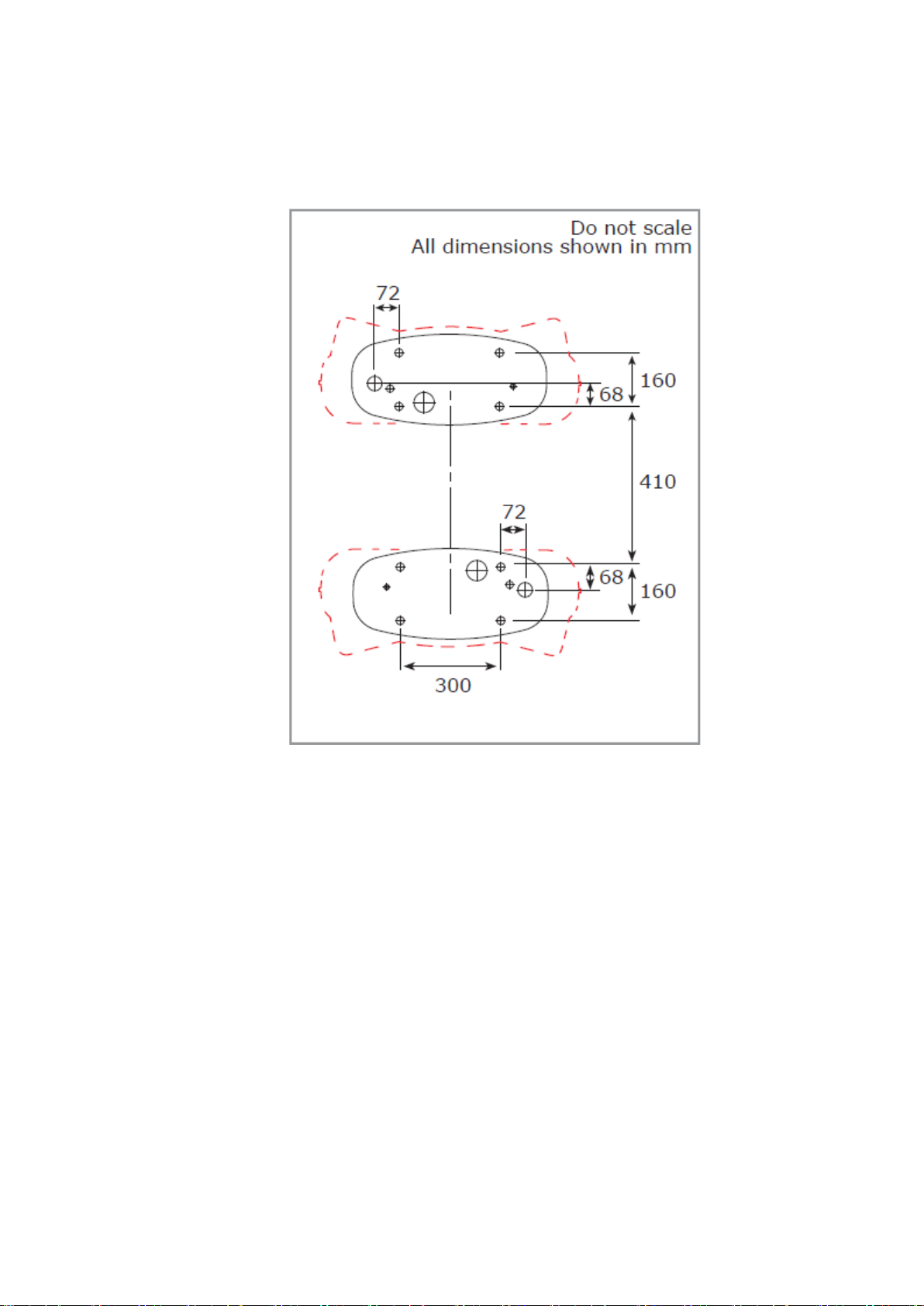
Ground fixing
The Veefil-RT is to be fixed to the ground through the baseplate fixing holes with 4 x M16 fasteners
(not supplied). The fasteners should fix the Veefil securely to the foundation through the baseplate and
protrude 30-40mm maximum from the foundation surface, in accordance with the dimensions and
fixing points shown in Figure1: Base plate dimensions. See also Figure 2: Dimensions walls or
obstacles, for installation against or near walls or other obstacles.
Foundation requirements
The foundation must be flat, even, and the appropriate density for the weight of the Veefil-RT. Check
the flatness and level of the foundation and level of the Veefil-RT baseplate prior to fixing.
Appropriate spacers may be used under the Veefil-RT baseplate to level the foundation. If spacers are
used, gaps are best filled, taking care not to damage the baseplate surface and edge.
Conduit fittings
Use 40mm flexible conduit, or Flexa system:
•Flexa PN 0237.202.036 conduit
•Flexa PN 5020.037.250 conduit fitting
•Flexa PN 0333.000.040 sealing washer
•Flexa PN 0561.000.040 locking ring
Communications
4G network capability or Ethernet.
The Veefil-RT is fitted with a Harting external IP65 rated ethernet port. This port can be accessed
temporarily during installation. If a more permanent, sealed connection is required, use Harting
external ethernet connector, 9153000401. See Wire and commission overview - step 4 for ethernet
port access.
RCD requirements
In some regions an RCD is required on the AC Input.
When using an RCD in the upstream supply, Tritium recommends Type B/B+ with 200mA trip current
and adjustable time selection. Nominal earth leakage current through the charger AC filter circuits can
be as high as 50mA, excluding transient events. Time selectivity can be used to reduce the likelihood
of nuisance RCD trips during grid transient events.
Note: If using a Type A RCD due to mandatory regional legislation/standards, it MUST be
accompanied by a Type B/B+ RCD to the same trip current. DC residual current could potentially
‘blind’ a Type A RCD, rendering it incapable of responding to a situation in which there is a genuine
risk of electric shock. A Type B RCD on the other hand provides a more comprehensive detection
capability for various residual fault currents, including smooth DC currents.
[GJ1]
Observe all pertinent national, regional, and local safety laws and regulations when installing and
commissioning.

VEEFIL-RT I NSTALLATION MANUAL
TRI93.INS.020
15 March 2023
© 2023 Tritium DCFC Limited | Commercial in confidence
7 of 30
Figure 1. Base plate dimensions
Figure 2. Dimensions walls or obstacles
Contact Tritium for installation advice if your minimum measurements are smaller than shown in
Figure 2 –Dimensions walls or obstacles.
VEEFIL-RT I NSTALLATION MANUAL
TRI93.INS.020
15 March 2023
© 2023 Tritium DCFC Limited | Commercial in confidence
8 of 30
Power supply preparation
The Veefil-RT is designed to accommodate power cabling in two different scenarios: through an
underground foundation, or above the ground.
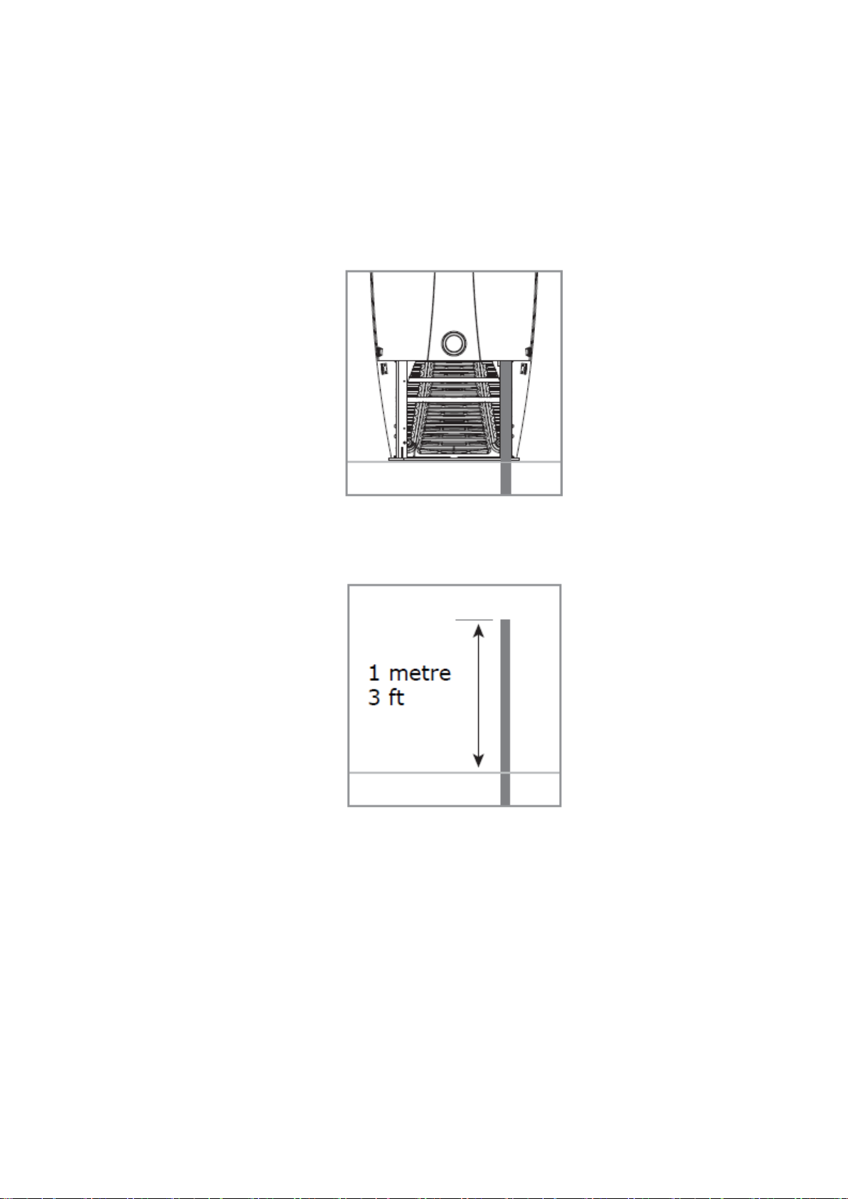
Underground power
When power cabling is provided from an underground foundation, it should enter the Veefil-RT
through the 50 mm base- plate hole as shown in Figure 1 –Base plate dimensions.
The 70mm baseplate hole should be used for an installation with an AC backpack only.
Figure 3.
When preparing the foundation, allow approximately 1 metre of power cabling from the foundation
surface as shown in Figure 4.
Figure 4.

VEEFIL-RT I NSTALLATION MANUAL
TRI93.INS.020
15 March 2023
© 2023 Tritium DCFC Limited | Commercial in confidence
9 of 30
Above ground power
When power cabling is supplied above the ground it will enter the Veefil-RT via the back radiator panel
on the left hand side as shown in Figure 5.
Figure 5.
Leave at least 1 metre of power cabling from the back left fixing point, for installation as shown in
Figure 6. Prior to installation the conduit and wiring will require trimming.
Figure 6.
Veefil-RT charging cable range
The standard Veefil-RT cable reach is approximately 2.0 metres as shown in these site layouts.
Customised lengths are also available. Contact your supplier should your requirements differ.
If longer length cables are used please ensure the cable is kept tidy and close to the Veefil-RT sides
at all times.

VEEFIL-RT I NSTALLATION MANUAL
TRI93.INS.020
15 March 2023
© 2023 Tritium DCFC Limited | Commercial in confidence
10 of 30
Single carparking bay
To service one car bay, 500mm of space is recommended between the car and the Veefil-RT front
and back for ease of use. Wheel stops installed at approximately 1200mm from the centre front of the
Veefil-RT can achieve this.
If the Veefil-RT is to be installed with its back or sides against or near a wall or other obstacle, use the
minimum distances shown in Figure 2: Dimensions walls or obstacles.
Figure 7.
VEEFIL-RT I NSTALLATION MANUAL
TRI93.INS.020
15 March 2023
© 2023 Tritium DCFC Limited | Commercial in confidence
11 of 30
Site configuration back to back units
When being installed back to back, a minimum distance of 300mm between the Veefil-RT chargers is
recommended. To ensure this minimum distance is observed use the dimensions for foundation
positioning in Figure 8.
Figure 8.
VEEFIL-RT I NSTALLATION MANUAL
TRI93.INS.020
15 March 2023
© 2023 Tritium DCFC Limited | Commercial in confidence
12 of 30
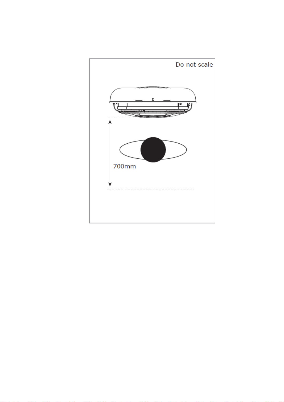
Site configuration servicing
An additional space of 700mm from the center front of the baseplate is required to open the front
panel for servicing, as shown in Figure 9.
Figure 9.

VEEFIL-RT I NSTALLATION MANUAL
TRI93.INS.020
15 March 2023
© 2023 Tritium DCFC Limited | Commercial in confidence
13 of 30
4 Installation requirements and equipment
These instructions provide a systematic
guide for installing and commissioning the
Veefil-RT.
The Veefil-RT must be installed and
serviced by qualified electrical personnel.
Observe all pertinent national, regional, and
local safety regulations when you install and
commission the Veefil-RT.
The Veefil-RT has an IP65 electronics
enclosure rating, however, as it must be
opened for installation, this is best done in
dry weather or under cover to avoid
moisture or debris ingress.
The Veefil-RT must be properly installed,
assembled and commissioned according to
these instructions before it is used. Prior to
installation contact your supplier to organise
commissioning information.
For height restricted areas alternative lifting
methods are available. Contact your
supplier for more information.
Tools and equipment supplied with Veefil-RT
•5mm pin hex tool to remove the M8 security screws fixing the plastic panels.
•Blanking plugs are fitted for transport and storage.
•40mm conduit fitting and seal, and M40 cable gland.
•Ferrite rings. See Wire and Commission section for instruction.
The Veefil-RT is shipped with a temporary single phase power cable which allows the unit to be
powered prior to installation. This allows for software updates, charger configuration and/or 4G
connectivity testing.
The cable has a male IEC socket and an IEC female lead is required to supply power.
If pre installation power up is required contact your supplier prior to the installation date to synchronize
with Tritium.

VEEFIL-RT I NSTALLATION MANUAL
TRI93.INS.020
15 March 2023
© 2023 Tritium DCFC Limited | Commercial in confidence
14 of 30
Equipment required
Lifting apparatus. See Packaging, handling and receipt for weights. Ensure lifting apparatus is
sufficiently rated.
If using conduit:
40mm standard flexible conduit or Flexa system. See Site configuration - Conduit fittings.
Tools
•Socket set and ratchet or adjustable spanner.
•Allen keys or socket set hex bits.
Sockets required
•8mm for radiator removal and service hatch removal.
•10mm socket for earthing strap removal.
•16mm for removal of shipping baseplate bolts.
•Metric hex 2.5mm bit to remove service cover.
•Jointing cement, or an approved external sealant.
VEEFIL-RT I NSTALLATION MANUAL
TRI93.INS.020
15 March 2023
© 2023 Tritium DCFC Limited | Commercial in confidence
15 of 30
5 Unpacking and installation preparation
Document Key
Items shown in orange are parts that require action for that step.
Step
Action
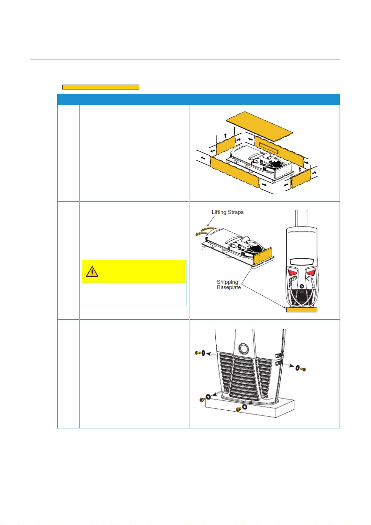
1
Move the crate as close to the prepared
installation site as possible. Ensure there
is enough room to manoeuvre the lifting
apparatus. Remove/slide out all crate
tubes to disassemble the cardboard
crate.
2
Securely attach the lifting straps at the
top of Veefil-RT to the lifting apparatus
and gently raise to a standing position on
the shipping baseplate.
Note: The Veefil-RT is 2050mm tall on
the shipping baseplate.
Once upright remove all wrapping.
CAUTION
Do not use the plug holders to assist
lifting the charger at any stage.
3
Remove front and rear radiator panels.
If access to the rear radiator panel is
difficult, the internal radiator may be
removed to access the rear base fixing
points. If so, remove the front radiator
panel only, and go to step 5.
Unscrew the 8x security screws and
remove them and the washers from both
radiator panels using the 5mm pin hex
tool.
Pull the radiator panels away from the
metalwork frame to remove.

VEEFIL-RT I NSTALLATION MANUAL
TRI93.INS.020
15 March 2023
© 2023 Tritium DCFC Limited | Commercial in confidence
16 of 30
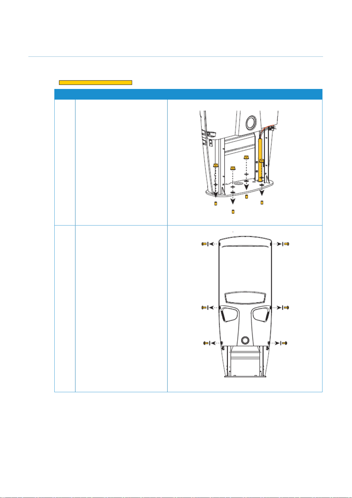
Step
Action
4
Remove the shipping bolts.
Use a 16mm socket to unscrew the 4x
bolts from the shipping base to
disengage.
Note: Keep the plastic inserts from the
bolts for later use.
Removing the radiator from the base of
the Veefil-RT gives more space for
bringing power into the unit, however,
removing the radiator is not always
required. Assess the situation on site.
5
Remove radiator (optional).
Unscrew the 4x nuts using an 8mm
socket. Pull the radiator off the fasteners
and sit the radiator on the base plate.
6
Reach behind and unclip the four way
connector. The four way connector is the
left hand plug attached to the underside
of the unit. Squeeze front clip and pull
down to release.

VEEFIL-RT I NSTALLATION MANUAL
TRI93.INS.020
15 March 2023
© 2023 Tritium DCFC Limited | Commercial in confidence
17 of 30
Step
Action
7
Disengage the radiator cooling system
from the unit.
Unclip the two quick release parts. One is
on the base behind the radiator, the other
is on the left side with the expansion bag.
Note: Do not twist or pull on the tubing
engaged with the metal quick release
parts.
Pull on the metal parts to release, and
press the metal parts together to join.
8
Store the radiator in a safe place
ensuring no damage to cooling hoses for
later re-assembly.
9
For the purpose of this manual, the
pictures in the following Installation
section display without the radiator.
Note: If a credit card reader is not
present, the lower area of the front panel
is covered with a Tritium-branded vinyl.
Remove if replacing the vinyl.
VEEFIL-RT I NSTALLATION MANUAL
TRI93.INS.020
15 March 2023
© 2023 Tritium DCFC Limited | Commercial in confidence
18 of 30
6 Installation
Document Key
Items shown in orange are parts that require action for that step.
Step
Action
1
Secure the unit to the foundation.
Lift the Veefil-RT by the supplied
lifting straps and place onto the
prepared foundation and secure.
If power cabling is supplied from
underground, feed through the
baseplate conduit hole.
Use the plastic inserts kept from
earlier step and place in the
baseplate holes.
2
Remove fasteners from front panel.
Remove the 6x security screws and
washers from the front panel using
the 5mm pin hex tool provided.

VEEFIL-RT I NSTALLATION MANUAL
TRI93.INS.020
15 March 2023
© 2023 Tritium DCFC Limited | Commercial in confidence
19 of 30
Step
Action
3
Place the front panel on the ground.
The front panel is attached to the
enclosure with wiring and an
earthing strap on the front left side.
Lift the front panel up to release
from the top hook and gently lower
to the ground in front of the Veefil-
RT.
Note: In calm conditions it may be
possible to keep the front panel
connected during commissioning. If
this is possible, go to step 5.
If in doubt, go to the next step and
disconnect the front panel and store
in a safe place until the unit is ready
to close for use.
4
Disconnect the front panel. There
are three points to disconnect:
1. Wiring to the top rear panel.
Squeeze the connector to
disconnect.
2. Earthing strap. Unscrew the
nut on the metalwork with a
10mm socket. Remove the
nut and earthing strap lug.
3. Connector ‘B’ on the HMI
panel. Connector ‘B’
detaches by squeezing the
connector front and rear with
your fingers and pulling
down.
Table of contents
Other Tritium Automobile Accessories manuals


Popular Automobile Accessories manuals by other brands

Cruz
Cruz Evo Rack Pro P30-140 Assembly instructions

Rockford Fosgate
Rockford Fosgate ELEMENT READY RFGNRL-K8 Installation & operation

Mountain Top
Mountain Top Roll installation manual

AMiO
AMiO 02558 user manual

Car Shades
Car Shades LRO-FREE-5-B installation manual

Curt Group
Curt Group ARIES S225045 installation manual


