Tritium Veefil TRI93-50-01 User manual

www.tritium.com
Veel®isaregisteredtrademarkofTritiumPtyLtd.©2014TritiumPtyLtd
Electricvehiclefastcharger
instructionmanual
Electric vehicle fast charger
instruction manual

2TRI93.134.5
www.tritium.com.au
Veel®isaregisteredtrademarkofTritiumPtyLtd.©2015TritiumPtyLtd
Important Safety Instructions and Specications. Save these instructions.............. 3
FCC Notice..................................................................................................................... 5
Packaging, Handling & Receipt..................................................................................... 6
Site Conguration & Fixing........................................................................................... 7
Installation requirements & equipment........................................................................ 14
Unpacking & installation preparation........................................................................... 16
Fix to ground & feed power.......................................................................................... 18
Wire & Commission. 1. WORLDWIDE (excluding USA)...............................................23
Wire & Commission 2. USA only................................................................................ 24
Closing checklist............................................................................................................ 25
Operating Instructions.................................................................................................. 27
Model TRI93-50-02
DC and AC charging specications............................................................................... 31
Site conguration & xing....................................................................... 32
Unpacking & installation preparation.........................................................35
Fix to ground and feed power ..................................................................36
Operating Instructions.................................................................................................. 39
Maintenance Instructions - all models......................................................................... 40
Contents

3TRI93.134.5
www.tritium.com.au
Veel®isaregisteredtrademarkofTritiumPtyLtd.©2015TritiumPtyLtd
Important Safety Instructions and
Specications. Save these instructions
This manual contains important instruc-
tions for the Veel® electric vehicle fast
charger models;
TRI93-50-01, 50kW dual DC (worldwide
excluding USA).
TRI93-50-01-US, 50kW dual DC (USA
market only).
TRI93-50-02, 50kW DC+AC (worldwide
excluding USA).
Model TRI93-50-02 specications, site
conguration and installation procedures
are described in pages 30 to 38.
These instructions must be followed
during installation, operation and mainte-
nance of the unit.
CAUTION
The Veel fast charger must be installed
and serviced only by qualied electrical
personnel.
To achieve EMC compliance, the chassis
of the Veel must be bonded to Earth
locally at the charger.
Grounding Instructions
This unit is to be connected to a ground-
ed, metal, permanent wiring system; and
an equipment-grounding conductor is to
be run with circuit conductors and
connected to equipment-grounding
terminal or lead on battery charger.
Connections to the battery charger shall
comply with all local codes and
ordinances.
All pertinent national, regional and local
safety laws and regulations must be
observed when installing and commis-
sioning the Veel fast charger.
Identifying Symbols
CAUTION
RISK OF ELECTRIC SHOCK
Equipment Grounding
Conductor Symbol
ø Phase Symbol
Alternating Current Supply
Symbol
Wiring Size
Worldwide (excluding USA)
3ø: 25mm2
Use 90°C Copper Wire
Take care to observe local regulations
regarding wiring different circuits in the
same conduit, including the ethernet
link if used. In general all conductors
occupying the same conduit shall have
an insulation rating equal to at least the
maximum circuit voltage applied to any
conductor within the conduit.

4TRI93.134.5
www.tritium.com.au
Veel®isaregisteredtrademarkofTritiumPtyLtd.©2015TritiumPtyLtd
USA only:
3ø: 4AWG
Use 90°C Copper Wire
Use 4 AWG insulated
grounding conductor
1ø: 18AWG
Use 90°C Copper Wire
An insulated grounding conductor that is
identical in size, insulation material and
thickness to the grounded and unground-
ed branch-circuit supply conductors ex-
cept that it is green with or without one
or more yellow stripes is to be installed
as part of the branch circuit that supplies
the unit or system. This grounding con-
ductor is to be grounded to earth at the
service equipment or, when supplied by a
separately derived system, at the supply
transformer.
Input:
Worldwide (excluding USA):
3ø WYE CONNECTED
230/400V, 240/415V ±10%
50Hz
55kW
USA Only:
3ø WYE CONNECTED
277/480V ±10%
60Hz
52kW
1ø, 120V
60Hz
250W
The Veel must be connected to a
circuit provided with appropriate
branch circuit over-current protection
in accordance with the National Elec-
trical Code, ANSI/NFPA 70.
Tightening Torque:
Wiring terminals:
4.0 Nm/35 lb-in
Service Hatch:
1.0 Nm/8.75 lb-in
Operating Temperature:
-20° to 50°C / -4° to 131°F
(-35°/-31°F optional)
Maximum Ambient
Temperature:
55°C /131°F
Weather Rating:
IP65 Electronics Enclosure
NEMA Type 3R
Important Safety Instructions and
Specications. Save these instructions

5TRI93.134.5
www.tritium.com.au
Veel®isaregisteredtrademarkofTritiumPtyLtd.©2015TritiumPtyLtd
FCC Notice
Information to the user
(FCC Part 15.105)
Class A product:
NOTE:
This equipment has been tested and
found to comply with the limits for a Class
A digital device, pursuant to part 15 of
the FCC rules. These limits are designed
to provide reasonable protection against
harmful interference when the equipment
is operated in a commercial environment.
This equipment generates, uses and
can radiate radio frequency energy and,
if not installed and used in accordance
with the instruction manual, may cause
harmful interference to radio communi-
cations. Operation of this equipment in a
residential area is likely to cause harmful
interference in which case the user will be
required to correct the interference at his
own expense.
Modication warning
(FCC Part 15.21)
In addition the user’s manual or
instruction manual shall caution the
user that changes or modications
not expressly approved by the party
responsible for compliance could void
the user’s authority to operate the
equipment (see below for example)
Warning: Any changes or modica-
tions not expressively approved by
(Tritium Pty Ltd) could void the us-
er’s authority to operate this equip-
ment

6TRI93.134.5
www.tritium.com.au
Veel®isaregisteredtrademarkofTritiumPtyLtd.©2015TritiumPtyLtd
Please note:
Read these instructions carefully to be-
come familiar with Veel packaging and
handling procedures prior to unpacking
and installation.
In all cases, the Veel is to be transport-
ed to the installation site in its original
packaging and only unpacked at the in-
stallation site.
Installation, commissioning and servicing
of the Veel should only be carried out
by qualied personnel.
Materials:
The Veel is transported in a reinforced
cardboard crate.
Please respect the environment and
recycle/reuse the materials.
Storage:
Store in the original packaging in a
horizontal position.
Storage temperature:
-20 to 45°C / -4 to 113°F.
Handling:
Only lift the Veel packaging in its
horizontal orientation using a forklift,
pallet jack or with lifting straps and en-
gine hoist, forklift or crane. Check the
weight on the delivery documents and
ensure the lifting apparatus used is com-
patible.
Receipt:
Check that the crate packaging is in good
condition and that the Veel is not dam-
aged.
If there are any problems noted, make a
formal complaint to the carrier and notify
your supplier.
Packed crate weight for models:
TRI93-50-01, 50kW dual DC
TRI93-50-01-US, 50kW dual DC
200kg/440lb
TRI93-50-02, 50kW DC+AC
(worldwide excluding USA)
230kg/507lb
Crate size for models:
TRI93-50-01, 50kW dual DC
TRI93-50-01-US, 50kW dual DC
850 x 2150 x 450mm
33.5 x 84.5 x 18 inches
TRI93-50-02, 50kW DC+AC
(worldwide excluding USA)
850 x 2140 x 630mm
33.5 x 84.5 x 25 inches
Packaging, Handling & Receipt
7TRI93.134.5
www.tritium.com.au
Veel®isaregisteredtrademarkofTritiumPtyLtd.©2015TritiumPtyLtd
Site Survey:
The installation site must be surveyed by
qualied engineer/s to determine the
correct ground preparation for the size
and weight of the Veel, in accordance
with local regulations.
The Veel is best installed following the
recommended site conguration
requirements.
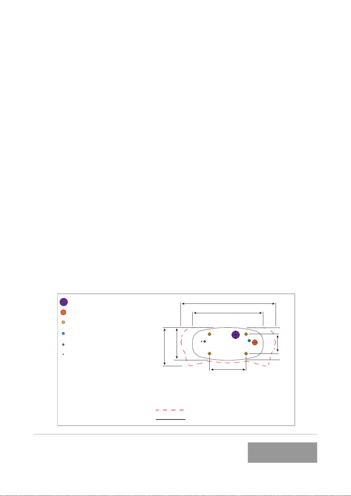
Ground Fixing:
The Veel is to be xed to the ground
through the baseplate xing holes with
4 x M16 or 5/8 inch fasteners (not sup-
plied). The fasteners should x the Veel
securely to the foundation through the
baseplate and protrude 30-40mm/1.2-1.6
inch maximum from the foundation
surface, in accordance with the dimen-
sions and xing points shown in:
Figure1: Base plate dimensions.
See Figure 6: Base template Walls for
installation against or near walls or other
obstacles.
Foundation Requirements:
The foundation must be at, even, and
the appropriate density for the weight of
the Veel.
Check the atness and level of the foun-
dation and level of the Veel baseplate
prior to xing.
Appropriate spacers may be used under
the Veel baseplate to level the
foundation.
If spacers are used, gaps are best lled,
taking care not to damage the baseplate
surface and edge.
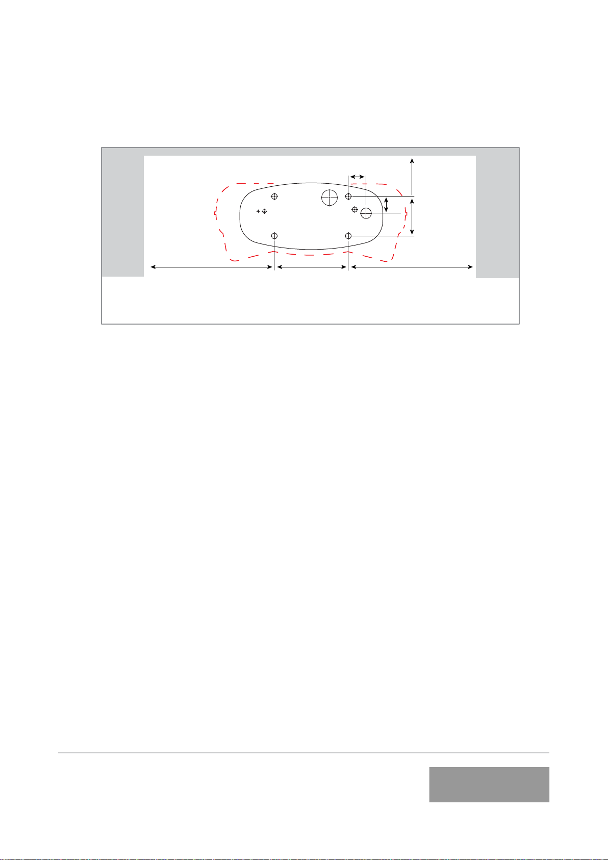
270
45mm conduit hole
Fixing point holes
Grounding conductor hole
Ethernet cable hole
Overall Dimensions
Baseplate = 10mm OR 3/8 inch thick
270
Grounding stud
All dimensions shown in mm
Do not scale
Figure 1. Base plate dimensions
750
580
160
300
VEEFIL FRONT
330
64mm conduit hole
Site Conguration & Fixing
8TRI93.134.5
www.tritium.com.au
Veel®isaregisteredtrademarkofTritiumPtyLtd.©2015TritiumPtyLtd
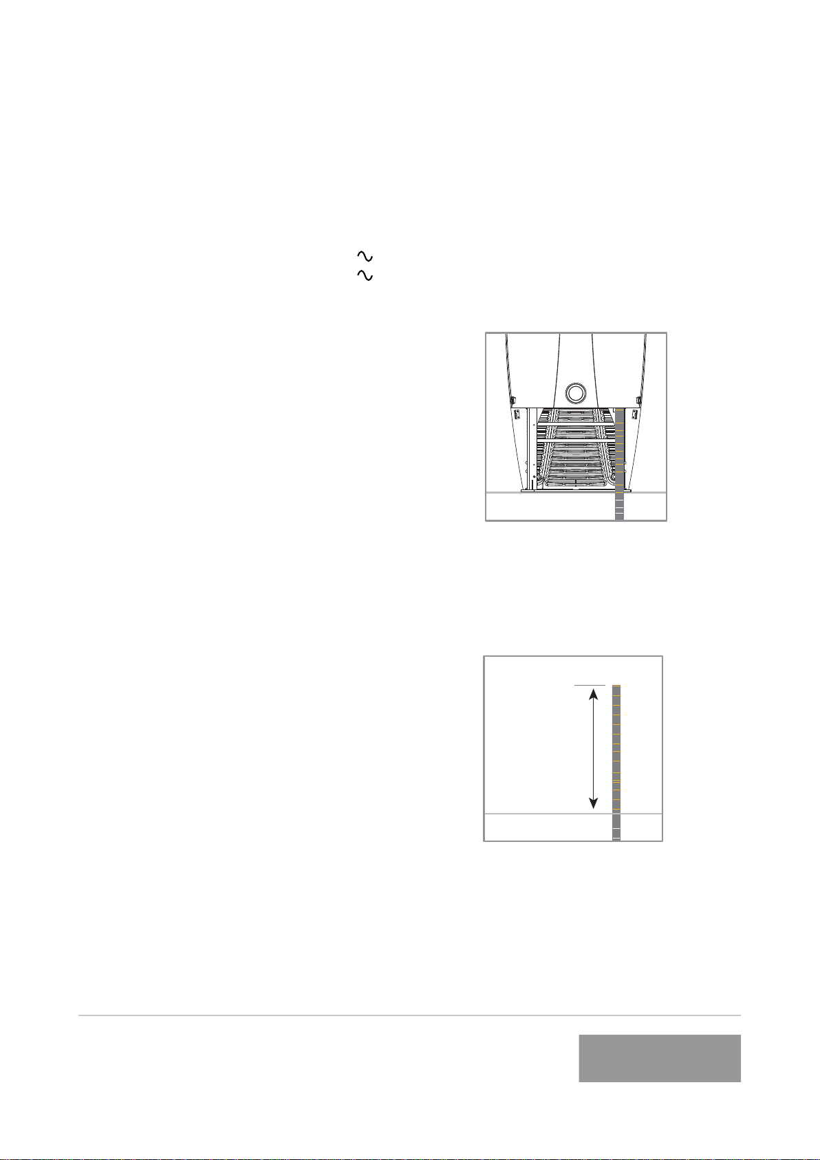
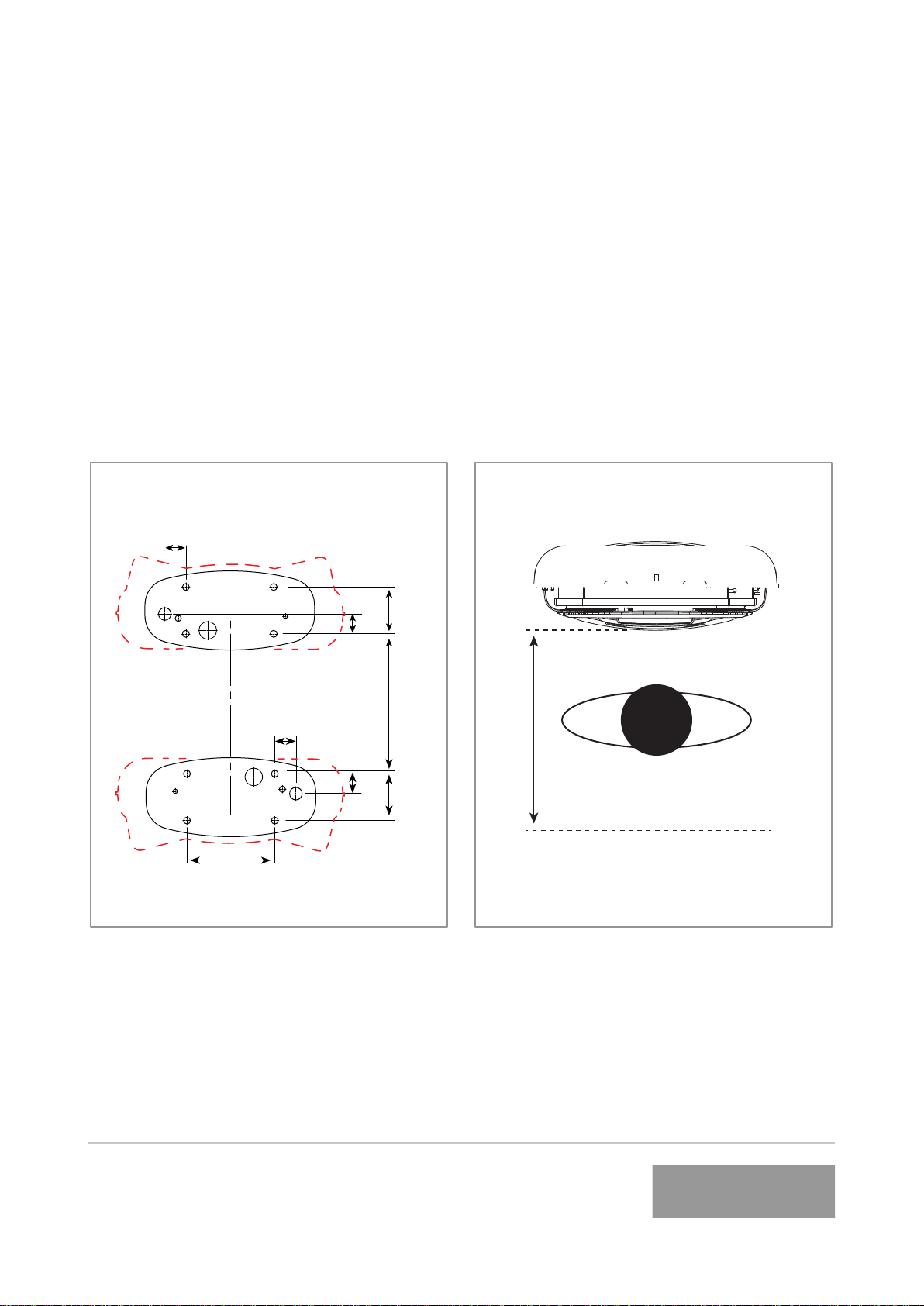
Underground power in conduit:
When power cabling is provided from
an underground foundation it enters the
Veel through the baseplate conduit hole
as shown in Figure 1 and Figure 2.
Figure 2.
When preparing the foundation, allow
approximately 1 metre/ 3 feet of conduit
and wiring from the foundation surface as
shown in Figure 3.
Figure 3.
1 metre
3 ft
Above ground power in conduit:
Electrical requirements:
Supply current:
Worldwide (excluding USA): 80A
USA only: 63A
Conduit ttings:
Worldwide (Excluding USA):
Use 40mm exible conduit, or Flexa
system:
Flexa PN 0237.202.036 conduit
Flexa PN 5020.037.250 conduit tting
Flexa PN 0333.000.040 sealing washer
Flexa PN 0561.000.040 locking ring
USA Only:
Flexa PN 0237.202.036 conduit
Flexa PN 5020.056.207 conduit tting
Flexa PN 0331.001.008 sealing washer
Flexa PN 0531.000.006 locking ring or 1
1/4” metal locking ring
Communications:
3G network capability or Ethernet.
Ethernet cable (if required)
Worldwide (Excluding USA):
Use 20mm exible conduit.
USA Only:
Use ENMT Schedule 40 PVC 3/4in
conduit.
Power supply preparation:
The Veel is designed to accommodate
power cabling in two different scenarios;
through an underground conduit, or with
conduit above the ground. Refer to the
installation instruction for full details on
installation and commissioning.
Site Conguration & Fixing
9TRI93.134.5
www.tritium.com.au
Veel®isaregisteredtrademarkofTritiumPtyLtd.©2015TritiumPtyLtd
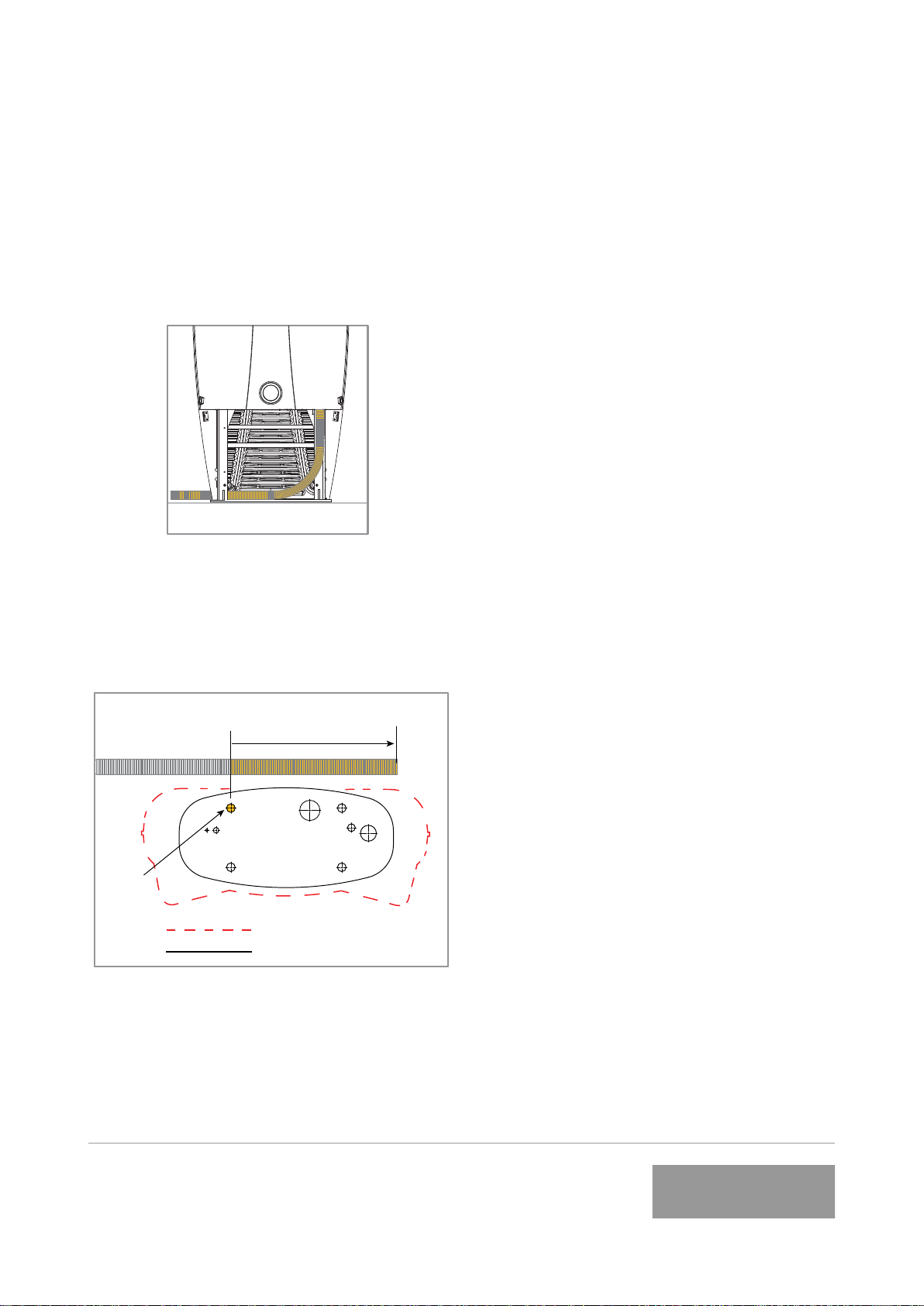
Site Conguration & Fixing
When power cabling is supplied above the
ground or down a wall it will enter the
Veel via the back radiator panel on the
left hand side as shown in Figure 4.
Figure 4.
Leave at least 1 metre/3 feet of conduit
and wiring from the back left xing point,
for installation as shown in Figure 5.
Prior to installation the conduit and wiring
will require trimming.
Figure 5. Top view
1 metre/3 feet
Overall footprint
Baseplate
Back
left
fixing
point
10 TRI93.134.5
www.tritium.com.au
Veel®isaregisteredtrademarkofTritiumPtyLtd.©2015TritiumPtyLtd
Site Conguration & Fixing
Veel charging cable range:
The standard Veel cable reach is approx-
imately 2.0 metres/6.5 feet as shown in
these site layouts.
Customised lengths are also available.
Contact your supplier should your require-
ments differ.
If longer length cables are used please en-
sure the cable is kept tidy and close to the
Veel sides at all times.
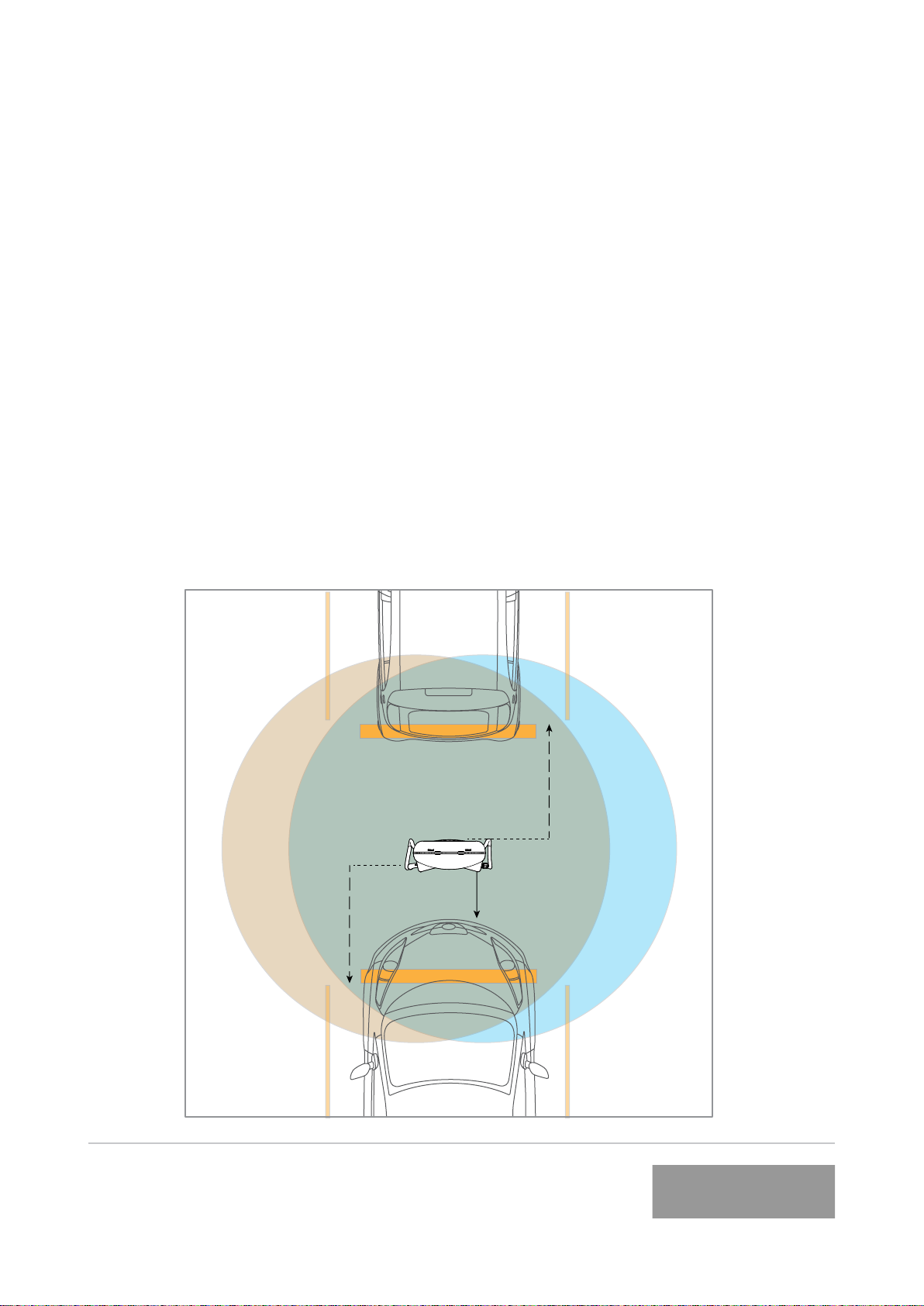
Single or back to back carparking
bays:
To service one car bay or back-to-back
car parking bays, 500mm/19.6 inches of
space is recommended between the car
and the Veel front and back for ease of
use.
Wheel stops installed at 1200mm/4 feet
from the centre front and back of the Veef-
il can achieve this.
If the Veel is to be installed with it’s back
or sides against or near a wall or other
obstacle, use the minimum distances
shown in Figure 8.
Top view
Do not scale
500
SAE Combo
Plug Range
CHAdeMO
Plug Range
1200
WHEEL
STOPS
1200
WHEEL
STOPS
Figure 6.
11 TRI93.134.5
www.tritium.com.au
Veel®isaregisteredtrademarkofTritiumPtyLtd.©2015TritiumPtyLtd
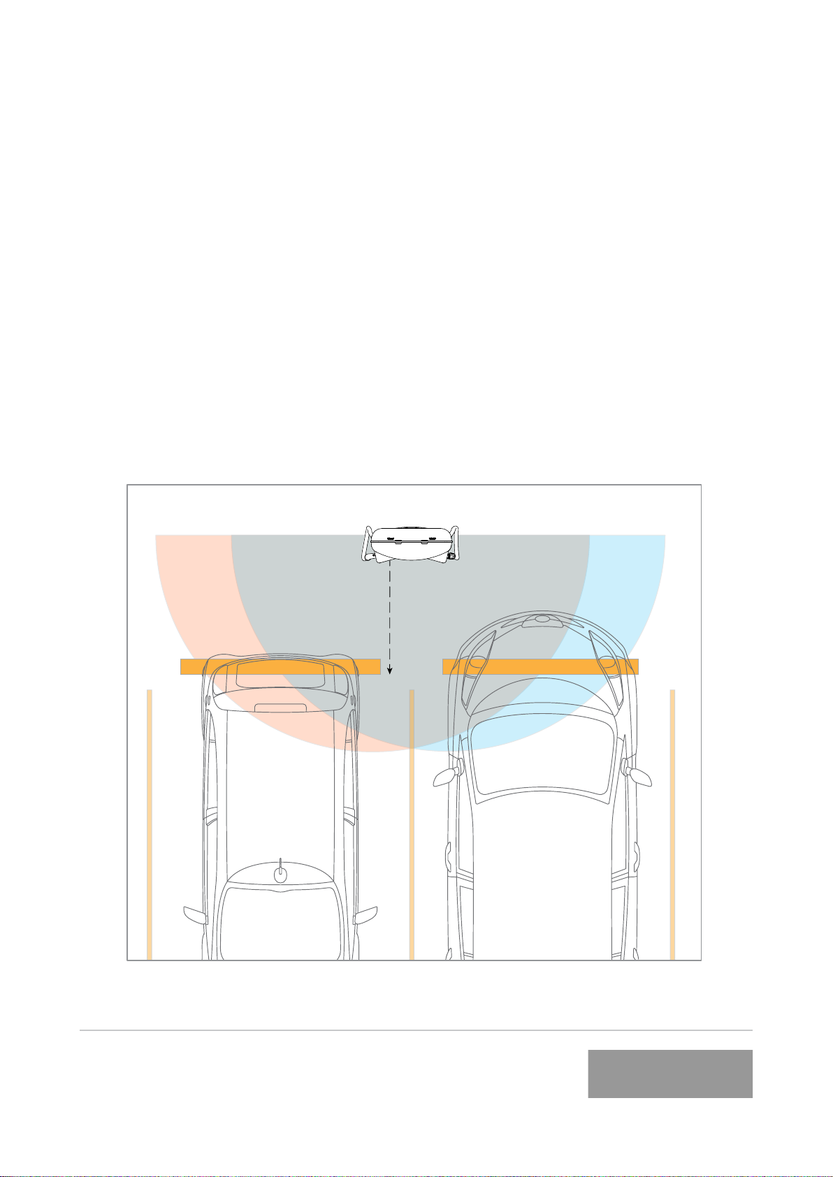
Multiple adjacent carparking bays:
To service two adjacent car parking bays,
it is recommended to install the Veel
inbetween the bays facing directly out.
Wheel stops a minimum of 1100mm/3.6
feet from the center front of the baseplate
are recommended to ensure enough space
between the cars and the Veel.
Site Conguration & Fixing
1100
WHEEL
STOPS
SAE Combo
Plug Range CHAdeMO
Plug Range
Top viewFigure 7.
Do not scale
If the Veel is to be installed with it’s
back or sides against or near a wall or
other obstacle, use the minimum distanc-
es shown in Figure 8.
12 TRI93.134.5
www.tritium.com.au
Veel®isaregisteredtrademarkofTritiumPtyLtd.©2015TritiumPtyLtd
Site Conguration & Fixing
725 minimum 725 minimum
72
68 160
250
300
All dimensions in mm
Do not scale
Wall Wall
Figure 8.
Dimensions walls or obstacles
Contact Tritium for installation advice if
your minimum measurements are smaller
than shown in Figure 8.
13 TRI93.134.5
www.tritium.com.au
Veel®isaregisteredtrademarkofTritiumPtyLtd.©2015TritiumPtyLtd
Site conguration back to back
units:
When being installed back to back, a
minimum distance of 300mm/12 inches
between the Veels is recommended.
To ensure this minimum distance is
observed use the dimensions for
foundation positioning in Figure 9.
72
68
68
160
160
410
72
300
Figure 9. Back to back units
All dimensions shown in mm
Do not scale
Site Conguration and Fixing
Site Conguration & Fixing
Site conguration servicing:
A additional space of 700mm/27.5 inches
from the center front of the baseplate is
required to open the front panel for
servicing, as shown in Figure 10.
Figure 10. Servicing distance
requirement
Do not scale
700mm
27.5 inches

14 TRI93.134.5
www.tritium.com.au
Veel®isaregisteredtrademarkofTritiumPtyLtd.©2015TritiumPtyLtd
Installation requirements & equipment
These instructions provide a systematic
guide for installing and commissioning
the Veel.
The Veel must be installed and serviced
by qualied electrical personnel.
All pertinent national, regional & local
safety regulations must be observed
when installing and commissioning the
Veel.
The Veel has an IP65 and NEMA Type 3R
electronics enclosure rating, however, as
it must be opened for installation, this is
best done in dry weather or under cover
to avoid moisture or debris ingress.
Installation shall not be done in a
commercial garage (repair facility) or
closer than 6 meters/20ft of an outdoor
motor fuel dispensing device.
The Veel must be properly installed,
assembled and commissioned according
to these instructions before it is used.
Prior to Installation contact your supplier
to organise commissioning information.
Supplied with Veel:
Blanking plugs are tted for transport and
storage.
Metric conduit ttings and seals are sup-
plied for installation (except USA).
Ferrite rings. See Wire and Commission
section for instruction.
Required equipment:
Lifting apparatus. The charger weighs
170kg/374 lbs, ensure lifting apparatus is
sufciently rated.
For height restricted areas alternative lift-
ing methods are available. Contact your
supplier for more information.
Worldwide (excluding USA):
40mm standard exible conduit or Flexa
40mm conduit - see pg 7.
USA only:
Flexa system - see pg 7.

15 TRI93.134.5
www.tritium.com.au
Veel®isaregisteredtrademarkofTritiumPtyLtd.©2015TritiumPtyLtd
5mm Pin Hex Bit & tool
Socket set & Ratchet or adjustable
spanner
Jointing Cement
If Ethernet cable is required use:
Worldwide (excluding USA):
20mm exible conduit
USA only:
Flexa 3/4” conduit.
DOCUMENT KEY:
Items shown in orange are parts that
require action for that step.
Installation requirements & equipment

16 TRI93.134.5
www.tritium.com.au
Veel®isaregisteredtrademarkofTritiumPtyLtd.©2015TritiumPtyLtd
1. Open Crate
Move the crate as close to the
prepared installation site as possible.
Ensure there is enough room to
manoeuvre the lifting apparatus.
Remove/slide out all crate tubes to
disassemble the cardboard crate.
2. Lift Veel to Vertical
Securely attach the lifting straps at the
top of Veel to the lifting apparatus and
gently raise to a standing position on the
shipping baseplate.
NOTE: The Veel is 2050mm/6.72ft tall
on the shipping baseplate.
Do not use the plug holders to assist
lifting the charger at any stage.
Once upright remove all wrapping.
Lifting Straps
Shipping
Baseplate
Unpacking & installation preparation

17 TRI93.134.5
www.tritium.com.au
Veel®isaregisteredtrademarkofTritiumPtyLtd.©2015TritiumPtyLtd
5. Remove radiator
Unsrew the 4x nuts to remove the radia-
tor. Slide the radiator off the fasteners,
and sit the radiator on the base plate.
Reach behind and unclip the four way
connector and cooling hoses to disen-
gage.
The four way connector is the left hand
plug attached to the underside of the
unit. Squeeze front clip and pull down to
release.
Unclip the 2x quick release cooling hoses
which are behind the radiator to com-
pletely disengage the radiator from the
unit. Store in a safe place ensuring no
damage to cooling hoses for later
re-assembly.
3. Remove front and rear radiator
panels
Unscrew the 4x security screws and
remove them and the washers from both
radiator panels using the 5mm Pin Hex
bit. Pull the radiator panels away from the
metalwork frame to remove.
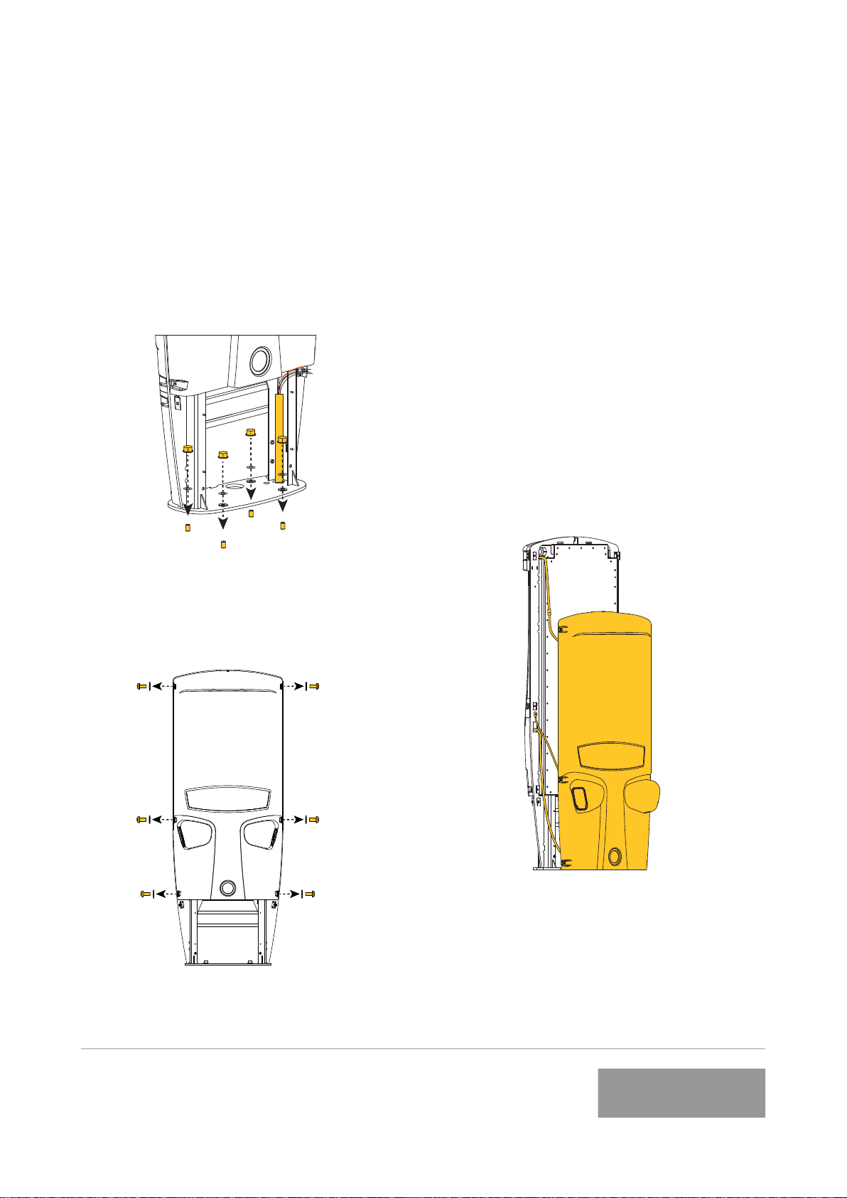
4. Remove shipping bolts
Unscrew the 4x bolts from the shipping
base to disengage.
If your installation supplies power from
above the ground, proceed to pg 17.
If your installation supplies power from
an underground foundation remove the
radiator.
Unpacking & installation preparation
18 TRI93.134.5
www.tritium.com.au
Veel®isaregisteredtrademarkofTritiumPtyLtd.©2015TritiumPtyLtd
Fix to ground & feed power
3. Place front panel on ground
The front panel is attached to the enclo-
sure with wiring and an earthing strap on
the front left hand side.
Lift the front panel up to release from the
top hook and gently lower to the ground
in front of the Veel.
In calm conditions it may be possible to
keep the front panel connected during
commissioning. If this is possbile, go to
page 18, item 5.
If in doubt, disconnect the front panel
(see pg 18, item 4) and store in a safe
place until the unit is ready to close for
use.
1. Secure to foundation
Lift the Veel and place onto the prepared
foundation and secure. If power cabling
in conduit is supplied from underground,
feed through the baseplate conduit hole.
2. Remove fasteners from front panel
Remove the 6x security screws and wash-
ers from the front panel.

19 TRI93.134.5
www.tritium.com.au
Veel®isaregisteredtrademarkofTritiumPtyLtd.©2015TritiumPtyLtd
5. Remove service covers
EXPLODED VIEW
Service
Cover
Service
Hatch
FRONT VIEW
Remove the service hatch and cover to
access the internal enclosure to prepare
the Veel for wiring.
The Service Hatch has an attached
gasket. Ensure this is carefully stored to
avoid damage or accumulation of debris.
The wiring diagram is on the inside of the
Service Hatch and also in this manual.
4. Disconnect front panel
There are three points to disconnect:
1. Wiring to the top rear panel.
Squeeze the connector to disconnect.
2. Earthing strap.
Unscrew the bolt on the metalwork.
Remove the bolt, earthing strap and
washers.
3. Connector ‘B’ on the HMI panel.
Connector ‘B’ detaches by squeezing the
connector front and rear with your ngers
and pulling down.
1
2
3
Fix to ground & feed power

20 TRI93.134.5
www.tritium.com.au
Veel®isaregisteredtrademarkofTritiumPtyLtd.©2015TritiumPtyLtd
6 b . F i t a b o v e g r o u n d c o n d u i t & f e e d
in power
Remove the blanking plug and replace
with supplied conduit tting and seal.
Feed the conduit from the rear right of
the unit and bend up into the conduit
tting. Remove the radiator if required.
(see Unpacking and Installation).
415V 3PH
Copper Conductors Only
N
x
Trim the conduit to t into the conduit
tting and feed a minimum of 300mm/12
inches of wiring through into the interior
ready for commissioning. Seal the con-
duit into the conduit tting with Jointing
Cement so that no water or debris can
enter.
Use the slots in the rear left channel to
cable tie the conduit in place if necessary.
6a. Fit underground conduit & feed
in power
If your installation has above ground
conduit, see 6b.
Remove the blanking plug and replace
with supplied conduit tting and seal.
Trim the conduit to t into the conduit
tting and feed a minimum of 300mm/12
inches of wiring through into the interior
ready for commissioning. Seal the con-
duit into the conduit tting with Jointing
Cement so that no water or debris can
enter.
415V 3PH
Copper Conductors Only
N
x
Fix to ground and feed powerFix to ground and feed power
This manual suits for next models
2
Table of contents
Other Tritium Automobile Accessories manuals


Popular Automobile Accessories manuals by other brands


ULTIMATE SPEED
ULTIMATE SPEED 279746 Assembly and Safety Advice

SSV Works
SSV Works DF-F65 manual

ULTIMATE SPEED
ULTIMATE SPEED CARBON Assembly and Safety Advice

Witter
Witter F174 Fitting instructions

WeatherTech
WeatherTech No-Drill installation instructions

TAUBENREUTHER
TAUBENREUTHER 1-336050 Installation instruction