Triton Blue TR-L72 User manual
! !
PROFESSIONAL HIGH POWER LED USER’S MANUAL
TR-L72
KEEP THIS MANUAL FOR FUTURE NEEDS

-2 - XM091 V1.0 NR
Every person involved with the installation, operation and maintenance of this
device has to
- be qualified
-follow the instructions of this manual
-consider this manual to be part of the total product
-keep this manual for the entire service life of the product
- pass this manual on to every further owner or user of the product
- download the latest version of the user manual from the Internet
INTRODUCTION:
Thank you for having chosen this professional LED lighting.
You will see you have acquired a powerful and versatile device.
Unpack the device. Inside the box you should find:
1. The fixture device
2. Two power cables
3. One XLR connection cable
4. One safety cable and this manual
Please check carefully that there is no damage caused by transportation. Should
there be any, consult your dealer and don’t install this device.
SAFETY INSTRUCTIONS

-3 - XM091 V1.0 NR
This device has left the factory in perfect condition. In order to maintain this
condition and to ensure a safe operation, it is absolutely necessary for the user to
follow the safety instructions and warning notes written in this user manual.
If the device has been exposed to temperature changes due to environmental
changes, do not switch it on immediately. The arising condensation could damage
the device. Leave the device switched off until it has reached room temperature.
This device falls under protection-class I. Therefore it is essential that the device
should be earthed.
The electric connection must carry out by qualified person.
If the external flexible cable or cord of this luminaire is damaged, it shall be
exclusively replaced by the manufacturer or his service agent or a similar qualified
person in order to avoid a hazard.
Make sure that the available voltage is not higher than stated at the end of this
manual.
Make sure the power cord is never crimped or damaged by sharp edges. If this
would be the case, replacement of the cable must be done by an authorized dealer.
Always disconnect from the mains, when the device is not in use or before cleaning
it. Only handle the power cord by the plug. Never pull out the plug by tugging the
power cord.
During initial start-up some smoke or smell may arise. This is a normal process and
does not necessarily mean that the device is defective, it should decrease gradually.

-4 - XM091 V1.0 NR
Please be aware that damages caused by manual modifications to the device are not
subject to warranty. Keep away from children and non-professionals.
Important:
Damages caused by the disregard of this user manual are not subject to
warranty. The dealer will not accept liability for any resulting defects or
problems.
DESCRIPTION OF THE DEVICE
Features
•3, 6or 15 DMX channels selectable for numerous applications
•Equippedwith72 x 1 W LEDs: 24x red, 24x blue, 24x green
•HighpowerLEDsmadebyLumileds,USA
•100000hours LED life
•TheLEDscan be controlled individually
•Switch-mode power supply
•Automaticpowersupplyadaptionbetween100 and 240 Volts without power
selector
•SteplessRGBcolourchanging•Programmablecolor-change speed and strobe
effect

-5 - XM091 V1.0 NR
•DMX-controlled operation or stand alone operation with Master/Slave-function
•Strobe-effect with 1-18 flashes per second
•Programmedchaser
•Rainbow-effect with adjustable speed
•AdvantagesofLED-technology: Extremely long life, low power consumption,
minimal heat emission, defact maintenance free with brilliant light radiation
•DMX-control via every standard DMX-controller
Overview
(1) Mounting bracket
(2) Floor-stand
(3) Fixation screw
(4) LEDs
(5) Housing
(6) DMX out
(7) DMX in
(8) Power output
(9) Power input
(10) Display
(11) Enter button
(12) Down button
(13) Up button
(14) ESC button

-6 - XM091 V1.0 NR
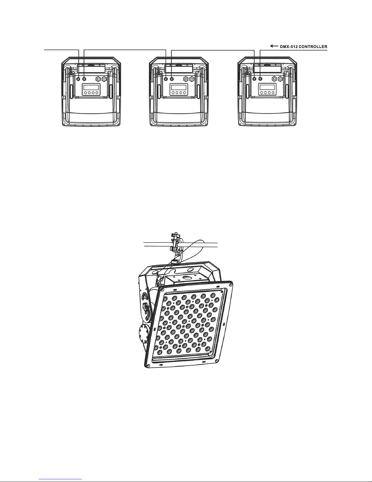
DMX-512 control connection
Connect the provided XLR cable to the female 3-pin XLR output of your controller
and the other side to the male 3-pin XLR input of the LED lighting. You can chain
multiple LED lighting together through serial linking. The cable needed should be
two core, screened cable with XLR input and output connectors. Please refer to the
diagram below.
DMX-512 connection with DMX terminator
For installations where the DMX cable has to run a long distance or is in an
electrically noisy environment, such as in a discotheque, it is recommended to use
a DMX terminator. This helps in preventing corruption of the digital control signal
by electrical noise. The DMX terminator is simply an XLR plug with a 120 Ω
resistor connected between pins 2 and 3,which is then plugged into the output XLR
socket of the last fixture in the chain. Please see illustrations below.
-7 - XM091 V1.0 NR
Please note: to ensure maximal stability, when the voltage is 120V, only five
devices may be connected together in this manner!From the sixth device, please
connect to power supply to get power for the second link; when the voltage is over
220V, only ten devices may be connected together in this manner!From the
eleventh device, please connect to power supply to get power for the second link.
Overhead rigging
Screw the bolt of the clamp into the hold of the bracket, and tighten the screw underneath.
Pull the safety-rope through the holes on the bracket of the base and over the trussing system or a
safe fixation spot. Insert the end in the carabine and tighten the safety screw.

-8 - XM091 V1.0 NR
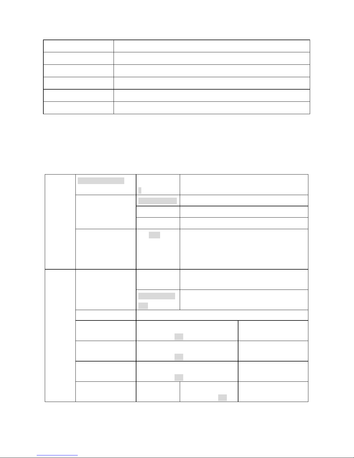
OPERATION
1:DMX Mode(3 Optional Mode ):
1): 15 channel mode(Each group can be control alone)
CH1
CH2
CH3
CH4
CH5
CH6
CH7
CH8
CH9
CH10
CH11
CH12
CH13
CH14
CH15
R
G
B
R
G
B
R
G
B
R
G
B
Preset
program
Strobe
Dimming
and speed
2): 6 DMX Mode(red, green, blue can be control alone)
CH1
CH2
CH3
CH4
CH5
CH6
R
G
B
Preset program
Strobe
Dimming and speed
3): 3 Channel mode
CH1
CH2
CH3
R
G
B
Further instruction:
From 1:Strobe channel and function
Strobe value
Function
0
Nofunction
1-95
Strobefromslowtofast
96-127
Nofunction
128-159
Pulsestrobefromslowtofast
160-191
Nofunction
192-223
Randomstrobefromslowtofast
224-255
Nofunction
From 2:Preset program
Value
Function
0--10
No function
11--40
Program 1
41--70
Program 2
-9 - XM091 V1.0 NR
71--100
Program 3
101--130
Program 4
131--160
Program 5
161--190
Program 6
191--220
Program 7
221--255
Program 8
When running the preset program, the last channel will be the speed channel(from slow to fast)
When no preset program,the last channel will be the dimming channel(from close to open)
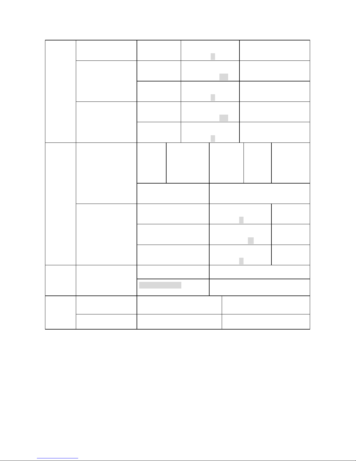
2:Manual mode:
<ADD SETTING >
DMX Channel:
1-512
Set address
Channels is: 003
3 channel mode
Channels is: 006
6 channel mode
<CHANNEL MODE>
Channels is: 015
15 channel mode
DmxMode
SET$TO$SLAVE$
ON/OFF
Set the unit to be slaver. When chosen this function,
the unit will turn to address 1 and 15 channels
mode; the running setting will be null until this
function OFF。
Mast_manual_C
on
Set to master, (include Play Scenes)
<MANUAL
CONTROL>
Alone_manual_
Con
Set to alone,( include Play Scenes)
<BLACK>
<STATIC RED >
Pre value: XXX
New value: 0 – 255
Dimming for red LED
<STATIC GREEN>
Pre value: XXX
New value: 0 – 255
Dimming for green LED
< STATIC BLUE >
Pre value: XXX
New value: 0 – 255
Dimming for blue LED
Preset Chase
<color mixing>
Red value
Pre value: XXX
New value: 0 – 255
Set red value

-10 - XM091 V1.0 NR
Green value
Pre value: XXX
New value: 0 –255
Set green value
Blue value
Pre value: XXX
New value: 0 – 255
Set blue value
Flash value
Pre value: XXX
New value: 0 –255
Set strobe value
Running Speed
Pre value: XXX
New value: 1 – 255
PRESET CHASE 1
Flash value
Pre value: XXX
New value: 0 –255
Running Speed
Pre value: XXX
New value: 1 – 255
PRESET CHASE 2
Flash value
Pre value: XXX
New value: 0 –255
Running Speed
Pre value: XXX
New value: 1 – 255
PRESET CHASE 3
Flash value
Pre value: XXX
New value: 0 –255
Running Speed
Pre value: XXX
New value: 1 – 255
PRESET CHASE 4
Flash value
Pre value: XXX
New value: 0 –255
Running Speed
Pre value: XXX
New value: 1 – 255
PRESET CHASE 5
Flash value
Pre value: XXX
New value: 0 –255
Running Speed
Pre value: XXX
New value: 1 – 255
PRESETCHASE6
Flash value
Pre value: XXX
New value: 0 –255
Running Speed
Pre value: XXX
New value: 1 – 255
PRESET CHASE 7
Flash value
Pre value: XXX
New value: 0 –255
PRESET CHASE 8
Running Speed
Pre value: XXX
New value: 1 – 255
-11 - XM091 V1.0 NR
Flash value
Pre value: XXX
New value: 0 –255
Running Speed
Pre value: XXX
New value: 1 – 255
PRESET CHASE 9
Flash value
Pre value: XXX
New value: 0 –255
Running Speed
Pre value: XXX
New value: 1 – 255
PRESET CHASE 10
Flash value
Pre value: XXX
New value: 0 –255
Manual
program
S_numberXX
s—channel’
value
s—chann
el’value
xxx
Manual
< EDIT SCENES >
download scene form
controller
S_numberXX
START SCENE
Pre value: XXX
New value: 1 –100
Set start scene
END SCENE
Pre value: XXX
New value: 1 – 35-100
Set ending
scene
Edit/PlayScenes
< PLAY SCENES >
SCENE TIME
Pre value: XXX
New value: 1 –255
Set scene time
Mast_sound_con
Set master sound mode
Sound
Mode
SOUND CONTROL
Alone_sound_con
Set alone sound mode
RESTORE SETTINGS
YES( ENTER)
Set the default setting
Others
Function
SOFTWARE VERSION
Vx.x
Check the software version

-12 - XM091 V1.0 NR
CLEANING AND MAINTENANCE
We recommend a frequent cleaning of the device. Please use a soft lint-free and
moistened cloth. Never use alcohol or solvents!
There are no servicable parts inside the device. Maintenance and service operations
are only to be carried out by authorized dealers.
Should you need any spare parts, please use genuine parts.
If the power supply cable of this device becomes damaged, it has to be replaced by
authorized dealers only in order to avoid hazards.
Should you have further questions, please contact your dealer.
INSTALLATION
This device is only constructed for a standing installation. The device must only be
installed absolutely planar at a vibration-free, oscilation-free and fire-resistant
location. Make sure that the device is installed absolutely planar by using a
water-level.
TECHNICAL SPECIFICATIONS
Power supply:100V~240V AC,50/60Hz~
Power consumption:max. 120 W
Packing dimensions:37x41x20CM
Net weight:6.5 KGS
Gross weight: 8.5 KGS
Remark:errors and omissions for every information given in this manual except. All information
is subject to change without prior notice.
Table of contents
Other Triton Blue Dj Equipment manuals

Triton Blue
Triton Blue PAR ZOOM 19x10W User manual

Triton Blue
Triton Blue 7R Beam Pro User manual

Triton Blue
Triton Blue TR-LED1020 User manual

Triton Blue
Triton Blue Sirius User manual

Triton Blue
Triton Blue SIRIUS 14 LED 3W RGB User manual

Triton Blue
Triton Blue MF-7 User manual

Triton Blue
Triton Blue TB-1500S User manual

Triton Blue
Triton Blue DIMMER 1 CANAL TR-D1 User manual

Triton Blue
Triton Blue TR 101 User manual

Triton Blue
Triton Blue TR-MP-574 User manual


