Triton 9600 Manual

SINGLE-CASSETTE
CASH DISPENSER
(MODELS 9600/9601/9620/9621)
INSTALLATION AND SERVICE
MANUAL
Version 4.1
TDN 07103-00034 03/00
TRITON SYSTEMS, INC.
COPYRIGHT NOTICE
Copyright © 2000 Triton Systems , Inc. All rights reserved. No part of this publication may be
reproduced, transmitted, transcribed, stored in a retrieval system, or translated into any human or
computer language, in any form, by any means whatsoever, without the express written permission
of Triton Systems, Inc.
CORPORATE HEADQUARTERS: RMA (RETURN MATERIAL AUTHORIZATION)
RETURN ADDRESS:
522 E. Railroad Street 21405 B Street
Long Beach, MS 39560 Long Beach, MS 39560
PHONE: (228) 868-1317
FAX: (228) 868-0437

ii
SINGLE-CASSETTE CASH DISPENSER INSTALLATION AND
SERVICE MANUAL
TRITON SYSTEMS, INC.
MODELS 9600/9601/9620/9621
FCC COMPLIANCE
Warning:
Changes or modifications to this unit not expressly approved by the
party responsible for compliance could void the user’s authority to
operate the equipment.
Note:
This equipment has been tested and found to comply with the limits
for a Class A digital device, persuant to Part 15 of FCC Rules. These
limits are designed to provide reasonable protection against harmful
interference when the equipment is operated in a commercial envi-
ronment. This equipment generates, uses, and can radiate radio fre-
quency energy and, if not installed and used in accordance with the
instruction manual, may cause harmful interference to radio com-
munications. Operation of this equipment in a residential area is
likely to cause harmful interference in which case the user will be
required to correct the interference at his own expence.
CANADIAN EMISSION REQUIREMENTS
This digital apparatus does not exceed the Class A limits for radio
noise emissions from digital apparatus set in the Radio Interference
Regulations of the Canadian Department of Communications.
Le present appareil numerique n’emet pas de bruits radioelectriques
depassant les limites applicables aux appareils numeriques de la Class
A prescrites dans le Reglement sur le brouillage radioelectrique edicte
par le ministere des Communications du Canada.
AUSTRALIAN EMISSION REQUIREMENTS
Warning:
This is a Class A product. In a domestic environment this product
may cause radio interference in which case the user may be re-
quired to take adequate measures.

TRITON SYSTEMS, INC.
iii
SINGLE-CASSETTE CASH DISPENSER INSTALLATION AND
SERVICE MANUAL
MODELS 9600/9601/9620/9621
NOTICE:
The Industry Canada label identifies certified equipment. This certification means that the
equipment meets telecommunications network protective, operational and safety requirements as
prescribed in the appropriate Terminal Equipment Technical Requirements document(s). The
Department does not guarantee the equipment will operate to the user’s satisfaction.
Before installing this equipment, users should ensure that it is permissible to be connected to the
facilities of the local telecommunications company. The equipment must also be installed using
an acceptable method of connection. The customer should be aware that compliance with the
above conditions may not prevent degradation of service in some situations.
Repairs to certified equipment should be coordinated by a representative designated by the sup-
plier. Any repairs or alterations made by the user to this equipment, or equipment malfunctions,
may give the telecommunications company cause to request the user to disconnect the equip-
ment.
Users should ensure for their own protection that the electrical ground connections of the power
utility, telephone lines and internal metallic water pipe system, if present, are connected together.
This precaution may be particularly important in rural areas. Caution: Users should not attempt
to make such connections themselves, but should contact the appropriate electric inspection au-
thority, or electrician, as appropriate.
NOTICE:
The Ringer Equivalence Number (REN) assigned to each terminal device provides an indication
of the maximum number of terminals allowed to be connected to a telephone interface. The ter-
mination on an interface may consist of any combination of devices subject only to the require-
ment that the sum of the Ringer Equivalence Numbers of all the devices does not exceed 5.

iv
SINGLE-CASSETTE CASH DISPENSER INSTALLATION AND
SERVICE MANUAL
TRITON SYSTEMS, INC.
MODELS 9600/9601/9620/9621
AVIS:
L’étiquette d’Industrie Canada identific le matériel homologué. Cette étiquette certifie que le
matériel est conforme aux normes de protection, d’exploitation et de sécurité des réseaux de
télécommunications, comme le prescrivent les documents concernant les exigences techniques
relatives au matériel terminal. Le Ministère n’assure toutefois pas que le matériel fonctionnera à
la satisfaction de l’utilisateur.
Avant d’installer ce matériel, l’utilisateur doit s’assurer qu’il est permis de le raccorder aux in-
stallations de 1’entreprise locale de télécommunication. Le maté-riel doit également être installé
en suivant une méthode acceptée de raccordement. L’abonné ne doit pas oublier qu’il est pos-
sible que la comformité aux conditions énoncées ci-dessus n’empêche pas la dégradation du ser-
vice dans certaines situations.
Les réparations de matériel homologué doivent être coordonnées par un représentant désigné par
le fournisseur. L’entreprise de télécommunications peut demander à I’utilisateur de débrancher
un appareil à la suite de réparations ou de modifications effectuées par l’utilisateur ou à cause de
mauvais fonctionnement.
Pour sa propre protection, l’utilisateur doit s’assurer que tous les fils de mise à la terre de la
source d’énergie électrique, des lignes téléphoniques et des canalisations d’eau métalliques, s’fl
y en a, sont raccordés ensemble. Cette précaution est particulièrement importante dans les
régions rurales. Avertissement: L’utilisateur ne doit pas tenter de faire ces raccordements lui-
même; il doit avoir recours à an service d’inspection des installations électriques, ou à un
électricien, selon le cas.
AVIS:
L’indice d’équivalence de la sonnerie (IES) assigné à chaque dispositif terminal indique le
nombre maximal de terminaux qui peuvent étre raccordés à une interface. La terminaison d’une
interface téléphonique peut consister en une combinaison de quelques dispositifs, à la seule con-
dition que la somme d’indices d’équivalence de la sonnerie de tous les dispositifs n’exède pas 5.

TRITON SYSTEMS, INC.
v
CONTENTS
SINGLE-CASSETTE CASH DISPENSER INSTALLATION AND
SERVICE MANUAL
MODELS 9600/9601/9620/9621
SECTION 1- INTRODUCTION ............................................................................................................. 1-2
WHAT’SINTHIS MANUAL .......................................................................................................... 1-2
WARNING, CAUTIONS AND NOTES .............................................................................................. 1-2
SECTION 2 - INSTALLATION AND SETUP ............................................................................................. 2-1
UNPACKING THE CASH DISPENSER ............................................................................................. 2-2
SECURING THE CASH DISPENSER TOTHE FLOOR ........................................................................ 2-3
INSTALLING THE DISPENSING MECHANISM .................................................................................... 2-4
COMPLETING THE PHYSICAL INSTALLATION ................................................................................... 2-5
TEST DISPENSE ....................................................................................................................... 2-7
TEST RECEIPT PRINTER ............................................................................................................ 2-7
RESET/TEST MODEM ............................................................................................................... 2-7
CONFIGURING THE TERMINAL FOR OPERATION ............................................................................. 2-7
SETTING THE COMBINATION LOCK .............................................................................................. 2-9
THE USER-CONFIGURABLE EPROM ACCESS CODE ..................................................................... 2-9
CHANGING THE EPROM ACCESS CODE .................................................................................... 2-9
ACCESSING THE MANAGEMENT FUNCTIONS MENU ....................................................................... 2-10
FUNCTION AVAILABILITY ...........................................................................................................2-11
MANAGEMENT FUNCTIONS CHART .............................................................................................2-11
FUNCTION: MANAGEMENT FUNCTIONS .......................................................................... 2-13
FUNCTION: CLOSE ............................................................................................................. 2-14
FUNCTION: SCHEDULE CLOSE ................................................................................... 2-15
FUNCTION: CHANGE SCHEDULE................................................................................ 2-16
FUNCTION: TRIAL CASSETTE BALANCE ................................................................... 2-17
FUNCTION: TRIAL CLOSE ............................................................................................ 2-18
FUNCTION: DAY CLOSE .............................................................................................. 2-19
FUNCTION: SEND TERMINAL TOTALS ....................................................................... 2-20
FUNCTION: ENTER QTY. IN CASSETTE ..................................................................... 2-21
FUNCTION: CASSETTE CLOSE ................................................................................... 2-22
FUNCTION: DIAGNOSTICS................................................................................................. 2-23
FUNCTION: STATUS ..................................................................................................... 2-24
FUNCTION: PURGE ....................................................................................................... 2-25
FUNCTION: TEST DISPENSE ....................................................................................... 2-26
FUNCTION: FORMAT MEMORY EXPANSION CARD .................................................. 2-27
FUNCTION: TEST RECEIPT PRINTER .......................................................................... 2-28
FUNCTION: VERSION #’S ............................................................................................. 2-29
FUNCTION: MORE DIAGNOSTICS ............................................................................... 2-30
FUNCTION: RESET/TEST MODEM ........................................................................ 2-31
FUNCTION: SCAN CARD......................................................................................... 2-32
FUNCTION: LANGUAGE/IDIOMA ........................................................................................ 2-33
FUNCTION: ENGLISH/INGLES....................................................................................... 2-34
FUNCTION: SPANISH/ESPANOL .................................................................................. 2-35
FUNCTION: ENABLE/DISABLE CUST. OPTION ........................................................... 2-36

vi
CONTENTS
SINGLE-CASSETTE CASH DISPENSER INSTALLATION AND
SERVICE MANUAL
TRITON SYSTEMS, INC.
MODELS 9600/9601/9620/9621
FUNCTION: JOURNAL ......................................................................................................... 2-37
FUNCTION: PRINT JOURNAL ....................................................................................... 2-38
FUNCTION: CLEAR JOURNAL ...................................................................................... 2-39
FUNCTION: PRINT LAST X ENTRIES........................................................................... 2-40
FUNCTION: PASSWORD MAINTENANCE ......................................................................... 2-41
FUNCTION: MASTER PASSWORD ............................................................................... 2-42
FUNCTION: ADMINISTRATION PASSWORD ............................................................... 2-43
FUNCTION: TERMINAL CONFIGURATION ........................................................................ 2-44
FUNCTION: PRINTER SETTINGS................................................................................. 2-45
FUNCTION: SET PRINT LENGTH ........................................................................... 2-46
FUNCTION: LOW RECEIPT PAPER ........................................................................ 2-47
FUNCTION: PRINTER GRAPHICS .......................................................................... 2-48
FUNCTION: RANDOM/LEVEL PRIZE COUPONS......................................................... 2-49
FUNCTION: ENTER PRIZE LEVEL MSG. ............................................................... 2-50
FUNCTION: ENTER RANDOM PRIZE MSG............................................................ 2-51
FUNCTION: ENABLE/DISABLE COUPON AWARDS .............................................. 2-52
FUNCTION: SET LEVEL PRIZE AMOUNT .............................................................. 2-53
FUNCTION: SET RANDOM WINNING % ................................................................ 2-54
FUNCTION: CHANGE MESSAGES ............................................................................... 2-55
FUNCTION: MARKETING MESSAGE ..................................................................... 2-56
FUNCTION: SURCHARGE MESSAGES ................................................................. 2-57
FUNCTION: WELCOME MESSAGE ........................................................................ 2-59
FUNCTION: SURCHARGE OWNER ........................................................................ 2-60
FUNCTION: CHANGE EXIT MESSAGE .................................................................. 2-61
FUNCTION: STORE MESSAGE .............................................................................. 2-62
FUNCTION: TERMINAL OWNER ............................................................................. 2-63
FUNCTION: TERMINAL PARAMETERS ....................................................................... 2-64
FUNCTION: SET TERMINAL # ................................................................................ 2-65
FUNCTION: RESET SEQ # ...................................................................................... 2-66
FUNCTION: SURCHARGE MODE ........................................................................... 2-67
FUNCTION: SURCHARGE PERCENT............................................................... 2-68
FUNCTION: ENABLE/DISABLE SURCHARGE MODE .................................... 2-69
FUNCTION: SURCHARGE LOCATION.............................................................. 2-70
FUNCTION: BLOCK ISO’S ................................................................................. 2-71
FUNCTION: SURCHARGE AMOUNT ................................................................ 2-73
FUNCTION: CASSETTE SETUP ............................................................................. 2-74
FUNCTION: LOW CURRENCY .......................................................................... 2-75
FUNCTION: INTERNATIONAL CURRENCY ....................................................... 2-76
FUNCTION: MAXIMUM AMOUNT ...................................................................... 2-77
FUNCTION: MULTIPLE AMOUNT ..................................................................... 2-78
FUNCTION: EXTENDED AMOUNTS ................................................................. 2-79
FUNCTION: FAST CASH AMOUNT ................................................................... 2-80
FUNCTION: KEY MANAGEMENT ............................................................................ 2-81
FUNCTION: ENTER MAC MASTER KEY .......................................................... 2-82

TRITON SYSTEMS, INC.
vii
CONTENTS
SINGLE-CASSETTE CASH DISPENSER INSTALLATION AND
SERVICE MANUAL
MODELS 9600/9601/9620/9621
FUNCTION: ENTER PIN MASTER KEY ............................................................ 2-84
FUNCTION: INJECT MASTER KEYS ................................................................ 2-86
FUNCTION: ENTER MAC WORKING KEY ........................................................ 2-87
FUNCTION: ENTER PIN WORKING KEY .......................................................... 2-89
FUNCTION: DOWNLOAD WORKING KEYS ..................................................... 2-91
FUNCTION: TELEPHONE ........................................................................................ 2-92
FUNCTION: PRIMARY NUMBER ....................................................................... 2-93
FUNCTION: BACKUP NUMBER ....................................................................... 2-94
FUNCTION: DATAPAK ACCESS CODE ............................................................ 2-95
FUNCTION: PREDIAL ON/OFF .......................................................................... 2-96
FUNCTION: COMPUSERVE ID .......................................................................... 2-97
FUNCTION: MODEM SETUP ............................................................................. 2-98
FUNCTION: DIAL MODE .............................................................................. 2-99
FUNCTION: DIAL RATE ............................................................................. 2-100
FUNCTION: BAUD RATE ........................................................................... 2-101
FUNCTION: MODEM SETUP STRING ...................................................... 2-102
FUNCTION: RESET/TEST MODEM ........................................................... 2-103
FUNCTION: MORE ................................................................................................. 2-104
FUNCTION: ADJUST VOLUME/CONTR .......................................................... 2-105
FUNCTION: RECEIPT OPTION ....................................................................... 2-106
FUNCTION: TRITON CONNECT ..................................................................... 2-107
FUNCTION: PRIMARY NUMBER ............................................................... 2-108
FUNCTION: BACKUP NUMBER ................................................................ 2-109
FUNCTION: ALARM NUMBERS ................................................................. 2-110
FUNCTION: PRIMARY ALARM NUMBER ............................................. 2-111
FUNCTION: BACKUP ALARM NUMBER ..............................................2-112
FUNCTION: ENABLE/DISABLE CALL BACK.............................................. 2-113
FUNCTION: ENABLE/DISABLE TRITON CONNECT .................................2-114
FUNCTION: ATM MONITORING ......................................................................2-115
FUNCTION: STATUS MONITORING ...........................................................2-116
FUNCTION: HEARTBEAT MESSAGE ......................................................... 2-117
FUNCTION: AD SCREENS .............................................................................. 2-120
FUNCTION: COMMUNICATION HEADER ....................................................... 2-121
FUNCTION: MORE ........................................................................................... 2-122
FUNCTION: ALARM THRESHOLDS .......................................................... 2-123
FUNCTION: SET LOW CASH THRESHOLD ....................................... 2-124
FUNCTION: SET JOURNAL THRESHOLD .......................................... 2-125
FUNCTION: SET SCHEDULED JOURNAL .......................................... 2-126
FUNCTION: VIEW/MODIFY OPTIONS ...................................................... 2-127
FUNCTION: ACTIVATE ......................................................................... 2-128
FUNCTION: DEACTIVATE .................................................................... 2-129
FUNCTION: SELECT FEATURE NUMBER ........................................... 2-130

viii
CONTENTS
SINGLE-CASSETTE CASH DISPENSER INSTALLATION AND
SERVICE MANUAL
TRITON SYSTEMS, INC.
MODELS 9600/9601/9620/9621
FUNCTION: DATE/TIME FUNCTIONS ............................................................................... 2-131
FUNCTION: SET DATE FORMAT ................................................................................. 2-132
FUNCTION: SET DATE / TIME ..................................................................................... 2-133
FUNCTION: SET DATE ........................................................................................... 2-134
FUNCTION: SET TIME ............................................................................................ 2-135
FUNCTION: TRANSACTION TYPES .................................................................................. 2-136
FUNCTION: ACCOUNT TYPES .......................................................................................... 2-137
SECTION 3 - TROUBLESHOOTING AND REPAIR .................................................................................... 3-1
CASH DISPENSER MODULE DISCRIPTION ..................................................................................... 3-2
09600-02001 CPU MODULE .................................................................................................. 3-2
09600-02002 MEMORY MODULE ............................................................................................. 3-2
09600-02003 COLOR MODEM/LCD MODULE ............................................................................ 3-2
09600-02005 MONOCHROME MODEM/LCD MODULE .................................................................. 3-2
09600-01004 BACKPLANE ...................................................................................................... 3-2
09600-00004 MEMORY EXPANSION MODULE ............................................................................. 3-3
09600-00031 MEMORY EXPANSION MODULE ............................................................................. 3-3
09600-00032 MEMORY EXPANSION MODULE ............................................................................. 3-3
09600-02030 QUADPORT MODULE. ......................................................................................... 3-3
09500-02009 ELECTRONIC JOURNAL/SECURITY MODULE ............................................................. 3-3
09600-01006 MAIN KEYPAD COLOR OPTION ............................................................................. 3-3
09600-01007 ABCD 4 KEY KEYPAD ....................................................................................... 3-3
09600-01009 EFGH 4 KEY KEYPAD ....................................................................................... 3-3
09600-02100 POWER SUPPLY WITH SURGE PROTECTOR ............................................................ 3-7
09600-02006 PRINTER CONTROLLER PCB ............................................................................... 3-7
09600-02008 RECEIPT PRINTER MECHANISM ............................................................................ 3-7
09600-02070 CDPD MODEM MODULE .................................................................................... 3-7
MAINTENANCE PHILOSOPHY ....................................................................................................... 3-7
DIAGNOSTICS .......................................................................................................................... 3-7
FIRST CHECK .......................................................................................................................... 3-7
IFYOU HAVE NODISPLAY ........................................................................................................ 3-8
DIAGNOSTIC MODE .................................................................................................................. 3-9
STATUS .................................................................................................................................. 3-9
PURGE ..................................................................................................................................3-11
TEST DISPENSE ...................................................................................................................... 3-11
TEST RECEIPT PRINTER ...........................................................................................................3-11
TEST JOURNAL PRINTER ......................................................................................................... 3-12
RESET / TEST MODEM ........................................................................................................... 3-12
ERROR CODES FROM THE TERMINAL ....................................................................................... 3-12
128 - ............................................................................................................................ 3-13
129 - ............................................................................................................................ 3-13
130 - ............................................................................................................................ 3-13
131 - ............................................................................................................................ 3-13
132 - ............................................................................................................................ 3-14

TRITON SYSTEMS, INC.
ix
CONTENTS
SINGLE-CASSETTE CASH DISPENSER INSTALLATION AND
SERVICE MANUAL
MODELS 9600/9601/9620/9621
133 - ............................................................................................................................ 3-14
134 - ............................................................................................................................ 3-14
135 - ............................................................................................................................ 3-14
136 - ............................................................................................................................ 3-14
138 - ............................................................................................................................ 3-15
139 - ............................................................................................................................ 3-16
140 - ............................................................................................................................ 3-16
141 - ............................................................................................................................ 3-16
142 - ............................................................................................................................ 3-17
143 - ............................................................................................................................ 3-17
144 - ............................................................................................................................ 3-17
145 - ............................................................................................................................ 3-17
146 - ............................................................................................................................ 3-18
147 - ............................................................................................................................ 3-18
148 - ............................................................................................................................ 3-18
149 - ............................................................................................................................ 3-18
150 - ............................................................................................................................ 3-18
151 - ............................................................................................................................ 3-18
152 - ............................................................................................................................ 3-18
153 - ............................................................................................................................ 3-18
154 - ............................................................................................................................ 3-18
155 - ............................................................................................................................ 3-18
157 - ............................................................................................................................ 3-18
158 - ............................................................................................................................ 3-18
159 - ............................................................................................................................ 3-19
160 - ............................................................................................................................ 3-19
161 - ............................................................................................................................ 3-19
162 - ............................................................................................................................ 3-19
163 - ............................................................................................................................ 3-19
164 - ............................................................................................................................ 3-19
165 - ............................................................................................................................ 3-19
166 - ............................................................................................................................ 3-19
182 - ............................................................................................................................ 3-19
183 - ............................................................................................................................ 3-19
185 - ............................................................................................................................ 3-20
186 - ............................................................................................................................ 3-20
187 - ............................................................................................................................ 3-20
188 - ............................................................................................................................ 3-20
189 - ............................................................................................................................ 3-20
192 - ............................................................................................................................ 3-20
195 - ............................................................................................................................ 3-20
196 - ............................................................................................................................ 3-20

x
CONTENTS
SINGLE-CASSETTE CASH DISPENSER INSTALLATION AND
SERVICE MANUAL
TRITON SYSTEMS, INC.
MODELS 9600/9601/9620/9621
203 - ............................................................................................................................ 3-20
205 - ............................................................................................................................ 3-20
206 - ............................................................................................................................ 3-20
209 - ............................................................................................................................ 3-20
210 - ............................................................................................................................ 3-20
ERROR CODES FROM THE DISPENSER ...................................................................................... 3-21
32 (20H) - ..................................................................................................................... 3-22
33 (21H) - ..................................................................................................................... 3-22
34 (22H) - ..................................................................................................................... 3-22
35 (23H) - ..................................................................................................................... 3-22
36 (24H) - ..................................................................................................................... 3-22
37 (25H) - ..................................................................................................................... 3-23
38 (26H) - ..................................................................................................................... 3-23
39 (27H) - ..................................................................................................................... 3-23
42 (2AH) -..................................................................................................................... 3-23
44 (2CH) - .................................................................................................................... 3-23
45 (2DH) - .................................................................................................................... 3-23
46 (2EH) -..................................................................................................................... 3-23
47 (2FH) - ..................................................................................................................... 3-23
48 (30H) - ..................................................................................................................... 3-24
49 (31H) - ..................................................................................................................... 3-24
50 (32H) - ..................................................................................................................... 3-24
51 (33H) - ..................................................................................................................... 3-24
52 (34H) - ..................................................................................................................... 3-24
53 (35H) - ..................................................................................................................... 3-24
54 (36H) - ..................................................................................................................... 3-24
55 (37H) - ..................................................................................................................... 3-24
56 (38H) - ..................................................................................................................... 3-24
MISCELLANEOUS ERROR CODES ........................................................................................ 3-25
REPAIRS ............................................................................................................................... 3-26
POWER SUPPLY ............................................................................................................... 3-26
FUSES ........................................................................................................................... 3-26
REMOVING THE POWER SUPPLY ........................................................................................ 3-27
INSTALLING APOWER SUPPLY ............................................................................................ 3-28
REMOVING A PRINTED CIRCUIT BOARD MODULE FROM THE CARD CAGE ................................ 3-30
INSTALLING APINTED CIRCUIT BOARD MODULE INTHE CARD CAGE ........................................ 3-33
REPLACING THE SSP04 BACKPLANE ................................................................................. 3-34
REMOVING AND INSTALLING THE PRINTER CONTROLLER MODULE ............................................ 3-37
REMOVING AND INSTALLING A THERMAL PRINTER .................................................................. 3-39
REMOVING AND REPLACING ANINVERTER MODULE .............................................................. 3-41
REPLACING THE MONOCHROME/COLOR LCD DISPLAY ........................................................... 3-43
REMOVING AND INSTALLING THE MAIN KEYPAD PCB ............................................................ 3-46
REMOVING AND INSTALLING THE 4-KEY KEYPADS .................................................................. 3-48

TRITON SYSTEMS, INC.
xi
CONTENTS
SINGLE-CASSETTE CASH DISPENSER INSTALLATION AND
SERVICE MANUAL
MODELS 9600/9601/9620/9621
REPLACING THE RUBBER KEY ASSEMBLIES FOR MAIN/SCREENKEYPADS .................................. 3-50
REMOVING AND INSTALLING THE CARD READER ................................................................... 3-50
REMOVING AND INSTALLING A DISPENSING MECHANISM ......................................................... 3-51
REMOVING AND INSTALLING ANELECTRONIC JOURNAL .......................................................... 3-55
DISPENSING MECHANISM LED OPERATION ................................................................................ 3-57
APPENDIX A - CASH DISPENSER SPECIFICATIONS .......................................................................... A-1
MODEL 9600 SINGLE-CASSETTE CASH DISPENSER (FRONT ACCESS) ............................................. A-2
MODEL 9601 SINGLE-CASSETTE CASH DISPENSER (REAR ACCESS) ............................................... A-5
MODEL 9620 SINGLE-CASSETTE CASH DISPENSER (FRONT ACCESS) ............................................. A-8
MODEL 9621 SINGLE-CASSETTE CASH DISPENSER (REAR ACCESS) ............................................. A-11
APPENDIX B - FIELD REPLACEABLE PARTS .................................................................................. B-1
ELECTRONIC MODULES ............................................................................................................. B-2
FRONT PANEL ......................................................................................................................... B-3
DISPENSER ............................................................................................................................. B-4
CABLES .................................................................................................................................. B-5
CABINETRY ............................................................................................................................. B-6
MISCELLANEOUS ...................................................................................................................... B-7
APPENDIX C - MECHANICAL COMBINATION LOCK INSTRUCTIONS ....................................................... C-1
ABOUT THE DIAL ..................................................................................................................... C-2
UNLOCKING 3-NUMBER COMBINATIONS ........................................................................................ C-2
TOLOCK ................................................................................................................................ C-2
CHANGING THE COMBINATION .................................................................................................... C-3
APPENDIX D - ELECTRONIC COMBINATION LOCK INSTRUCTIONS ....................................................... D-1
ENTERING COMBINATION ........................................................................................................... D-2
CHANGING COMBINATION .......................................................................................................... D-2
LOCKOUT FEATURE .................................................................................................................. D-2
BATTERY REPLACEMENT ........................................................................................................... D-2
APPENDIX E - USER-CONFIGURABLE EPROM ACCESS CODE ........................................................ E-1
CHANGING THE ACCESS CODE FOR NEW INSTALLATIONS ................................................................ E-2
CHANGING THE EXISTING ACCESS CODE ..................................................................................... E-3
WHAT TO DO IF THE ACCESS CODE IS UNKNOWN .......................................................................... E-4
APPENDIX F - LOADING SOFTWARE ............................................................................................. F-1
DEFINITIONS AND EXPLANATIONS ................................................................................................ F-2
SOFTWARE FILES EXPLAINED ..................................................................................................... F-2
WHAT YOU NEED TO GET STARTED ........................................................................................... F-3
DOWNLOAD VIA MODEM ............................................................................................................ F-3
DOWNLOAD VIA PC ................................................................................................................. F-3

xii
CONTENTS
SINGLE-CASSETTE CASH DISPENSER INSTALLATION AND
SERVICE MANUAL
TRITON SYSTEMS, INC.
MODELS 9600/9601/9620/9621
STARTING THE SOFTWARE DOWNLOAD ........................................................................................ F-4
LOADING THE SOFTWARE USING TRICOMM .............................................................................. F-4
PREPARING THE CASH DISPENSER FOR PROGRAM/FILE DOWNLOADING ............................................ F-5
APPENDIX G - WARRANTY AND REPAIR POLICIES/PROCEDURES ....................................................... G-1
PARTS-ONLY LIMITED MANUFACTURER’SWARRANTY ..................................................................... G-3
DISCLAIMER OF WARRANTIES ..................................................................................................... G-3
SHIPPING DAMAGE ...................................................................................................................G-4
AUTHORIZED INSTALLATION AND SERVICE PROVIDERS ..................................................................... G-5
TRITON’STECHNICAL SERVICES DEPARTMENT ..............................................................................G-5
EQUIPMENT FAILURES WITHIN THE WARRANTY PERIOD ..................................................................G-6
EQUIPMENT FAILURES BEYONDTHE WARRANTY PERIOD ................................................................. G-7
CONTACT INFORMATION ............................................................................................................. G-9
INDEX ........................................................................................................................................ I-1

SECTION 1
INTRODUCTION

1-2
SECTION 1 - INTRODUCTION
SINGLE-CASSETTE CASH DISPENSER INSTALLATION AND
SERVICE MANUAL
TRITON SYSTEMS, INC.
MODELS 9600/9601/9620/9621
1-2
TRITON SYSTEMS, INC.
WHAT’SINTHIS MANUAL
This manual contains important information you will need to install and maintain your Triton
Systems Cash Dispenser (Models 9600/9601/9620/9621). Additional information pertaining to
the operation of your Cash Dispenser is included in the Single-Cassette Cash Dispenser Operation
Manual (Models 9600/9601/9620/9621).
SECTION 2 - Installation and Setup contains information and procedures that will assist service
and installation personnel that install and setup a Single-Cassette Cash Dispenser. This section
includes information about site selection and preparation, power and communication requirements
and terminal setup procedures.
SECTION 3 - Troubleshooting provides a brief description of the major components that make up
the Cash Dispenser. It describes step-by-step fault isolation and repair procedures to assist service
personnel in maintaining the Cash Dispenser. It contains information about error codes and sug-
gested courses of action to repair the Cash Dispenser. In addition, this section provides detailed
procedures that describe how to remove and replace each of the field replaceable components that
comprise the Cash Dispenser.
APPENDIX A consists of the Technical Specifications for the Single-Cassette Cash Dispenser
models covered in this manual.
APPENDIX B provides a list of part numbers and descriptions for all field replaceable compo-
nents for Single-Cassette Cash Dispensers.
APPENDIX C contains procedures for changing the combination of the manual-type combination
lock.
APPENDIX D contains procedures for changing the combination of the electronic combination
lock.
APPENDIX E contains procedures for changing the Cash Dispenser’s EPROM access code.
APPENDIX F contains procedures for loading terminal operating software into the Cash Dis-
penser.
APPENDIX G contains warranty and repair policies and procedures.

1-3
SINGLE-CASSETTE CASH DISPENSER INSTALLATION AND
SERVICE MANUAL
TRITON SYSTEMS, INC.
SECTION 1 - INTRODUCTION
MODELS 9600/9601/9620/9621
WARNINGS, CAUTIONS AND NOTES
Warnings, cautions, and notes provide information which you need to consider.
A WARNING indicates that a certain action can potentially give you an electrical shock.
A CAUTION indicates that a defined action may cause damage to the Cash Dispenser or one of its
components.
A NOTE can influence your decision on how to respond to the information in the section you are
currently reading.


SECTION 2
INSTALLATION AND SETUP

SECTION 2 - INSTALLATION AND SETUP
2-2
TRITON SYSTEMS, INC.
MODELS 9600/9601/9620/9621
SINGLE-CASSETTE CASH DISPENSER INSTALLATION AND
SERVICE MANUAL
UNPACKING THE CASH DISPENSER
1. Carefully inspect the unit for any shipping damage and report any damage immediately to the
shipping company. Refer to the Warranty Information in Appendix G for more information
about reporting shipping damage.
2. Remove the unit from the carton by cutting the straps and removing the top of the box.
3. Remove the loose packing material from inside of the box.
4. Remove the silver key from the white plastic bag attached to the Cash Dispenser wrapping.
5. Stand the unit up.
6. “Walk”the unit out of the carton and remove the protective plastic bag.
7. Use the silver-colored key to open both the Control Panel and the Fascia Door on the front of
the cabinet (which conceals the locking mechanism).
8. Turn the handle on the locking mechanism to open the front enclosure door.
9. Remove the accessory kit from inside the bottom enclosure and open and inspect the contents.
Check the contents against the enclosed packing list. Report any missing parts to Triton
immediately.
**IMPORTANT**
The Cash Dispenser is designed for indoor use only!
**NOTE**
The top enclosure access door is provided with a pneumatic piston to prevent the door
from extending too far when opening and from being closed too quickly. In the un-
likely event of the pneumatic piston not functioning properly, the door should be pre-
vented from opening too far and from being slammed when closing.

SECTION 2 - INSTALLATION AND SETUP
2-3
TRITON SYSTEMS, INC.
MODELS 9600/9601/9620/9621 SINGLE-CASSETTE CASH DISPENSER INSTALLATION AND
SERVICE MANUAL
SECURING THE CASH DISPENSER TOTHE FLOOR
1. “Walk”the Cash Dispenser to the location where it will be installed. Locate the four anchor
bolt holes in the bottom the cabinet. Mark the location of the four holes on the floor as guides
for the holes that will be used for the anchor bolts (supplied by the installer) that secure the
cabinet.
2. Move the Cash Dispenser away from the installation location. Use a half-inch drill bit to drill
four holes at least 2 inches deep into the floor. Refer to Appendix A, Cash Dispenser
Specifications, for mounting bolt patterns applicable to each model Cash Dispenser.
3. Return the Cash Dispenser to the installation location and align the base over the four holes.
Place the four anchor bolts through the cabinet base into the holes in the floor. Sleeve anchors
(1/2 inch by 4 1/4 inches) are recommended to attach the unit to the floor. Tap the four anchor
bolts into the concrete.
4. Use a carpenter's level to make sure that the cabinet is level front to back and side to side. The
four leveling bolts in the bottom of the cabinet can be adjusted with an adjustable wrench.
5. Attach the four nuts to the anchor bolts and tighten firmly.
**IMPORTANT**
To ensure the stability and security of the Cash Dispenser, the unit must
be secured to the mounting surface!
**CAUTION**
The Cash Dispenser is prone to tipping over if the cash dispenser tray is
extended when the unit is not secured to the floor!
The unit was shipped with the combination lock unlocked. If it has become locked, a manual
lock can be unlocked by turning the dial at least four complete revolutions counter-clockwise
(to the left), stopping on 50 at the main (opening) index. Then turn the dial counter-clockwise
to retract the bolt. (Enter 123456 if the cabinet has an electronic lock.) Turn the dial clockwise
(to the right) until it stops (approximately 90 degrees) to unlock the door and rotate the “T”
handle to open the door.

SECTION 2 - INSTALLATION AND SETUP
2-4
TRITON SYSTEMS, INC.
MODELS 9600/9601/9620/9621
SINGLE-CASSETTE CASH DISPENSER INSTALLATION AND
SERVICE MANUAL
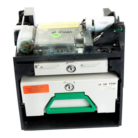
INSTALLING THE DISPENSING MECHANISM
1. Verify that the power switch located inside the
top of the cabinet is in the OFF (“0”) position.
Remove the packing material from the ends of
the cables that are hanging inside the cabinet.
2. Unpack and remove the Cash Dispenser
mechanism from its shipping container.
3. Pull the cassette tray out to its fully extended
position as shown in Figure 2-1.
4. Pick up the dispensing mechanism and place
it on the cassette tray. Leave enough room to
easily access the back of the dispensing
mechanism so it can be connected to the cables
coming from the Cash Dispenser.
5. Refer to Figure 2-2. Connect cable 9600-0043
to the DB25 connector (PL6) on the rear the
dispenser mechanism. Secure the DB25 cable
to the dispenser with two screws attached to the connector. Insert the Molex power plug attached
to cable 9600-0013 into the connector marked PL2. This plug is keyed so that it can only be
inserted in one direction.
6. Install the dispensing mechanism by sliding the end with the circuit board into the tray in the
cabinet. The mechanism should slide under two tabs in the rear, and the front edge slots should
align with the two bolts provided with wing nuts. Once the mechanism is fully engaged into
the tray tighten the wing nuts by hand.
Cable
9600-0013
Cable
9600-0043
Figure 2-2. Connect cables 9600-0013 and 9600-0043
as shown to the left
Figure 2-1. The Model 9600/9620 Cassette
Tray pulled out to its fully extended position.
**CAUTION**
Be certain that you have not applied power
to the Cash Dispenser before you continue!
Other manuals for 9600
2
This manual suits for next models
3
Table of contents
Other Triton Dispenser manuals