HIKOKI M 12V2 User manual

Router
Fresadora
木工雕刻機
Máy phay
M 12V2 •M 12SA2
Handling instructions
Instrucciones de manejo
使用說明書
Hướng dẫn sửdụng
M12V2
Read through carefully and understand these instructions before use.
Leer cuidadosamente y comprender estas instrucciones antes del uso.
使用前務請詳加閱讀
Đọc kỹvà hiểu rõ các hướng dẫn này trước khi sửdụng.
000BookM12V2Asia.indb1000BookM12V2Asia.indb1 2019/01/2115:24:292019/01/2115:24:29

2
12
34
56
78
^
$
#
!
7
%
&
*
7
3
6
5
78
9
2
1
4
0
@
000BookM12V2Asia.indb2000BookM12V2Asia.indb2 2019/01/2115:24:302019/01/2115:24:30

3
910
11 12
13 14
15 16
w
q
*()
*
p
o
p
y
t
ua
df
gh
s
s
i
q
r
e
A
000BookM12V2Asia.indb3000BookM12V2Asia.indb3 2019/01/2115:24:302019/01/2115:24:30

4
17 18
19 20
21 22
l
j
k
v
x
u
a
z
c
a
;
;
p
c
000BookM12V2Asia.indb4000BookM12V2Asia.indb4 2019/01/2115:24:302019/01/2115:24:30

5
English Español 中國語
1Lock pin Pasador de cierre 鎖銷
2Wrench Llave para tuercas 扳手
3Loosen Soltar 旋松
4Tighten Apretar 旋緊
5Stopper pole Polo del dispositivo de ajuste 止動杆
6Scale Escala 刻度片
7Quick adjustment lever Palanca de ajuste rápido 快速調整杆
8Depth indicator Indicador de profundidad 深度指針
9Pole lock knob Perilla de cierre del polo 杆固定旋鈕
0Stopper block Bloque del dispositivo de ajuste 止動塊
!
Counter-clockwise direction
Sentido contrario a las agujas del
reloj 逆時針方向
@Loosen the lock lever Aflojar la palanca de cierre 旋松固定杆
#Knob Perilla 旋鈕
$Fine adjustment knob Control de ajuste preciso 微調旋鈕
%Clockwise direction Sentido de las agujas del reloj 時針方向
^Cut depth setting screw Tornillo de ajuste de la profundidad
de corte 切割深度設定螺絲
&Screw Tornillo 螺絲
*Template guide adapter Adaptador de guía patrón 模板導架附加器
(Centering gauge Indicador de centrado 定心規
)Collet chuck Boquilla de mordazas 夾盤
qTemplate guide Guía patrón 模板導架
wScrew Tornillo 螺絲
eTemplate Patrón 模板
rBit Broca 鑽頭
tStraight guide Guía derecha 直導架
yGuide plane Plano guía 導面
uBar holder Sujetador de barra 導杆固定器
iFeed screw Tornillo alimentación 進給螺杆
oGuide bar Barra de guía 導杆
pWing bolt (A) Perno de aletas (A) 碟形螺栓(A)
aWing bolt (B) Perno de aletas (B) 碟形螺栓(B)
sTab Pestaña 調整片
dDust guide Guía de polvo 碎屑導架
fScrew Tornillo 螺絲
gDust guide adapter Adaptador de guía de polvo 碎屑導架附加器
hDial Dial 撥盤
jStopper bolt Perno del dispositivo de ajuste 止動螺栓
kSpring Muelle 彈簧
lSeparate Separado 隔片
;Router feed Alimentación de la fresadora 刨槽機進給
zWorkpiece Pieza de trabajo 工作材料
xRotation of bit Rotación de la broca 鑽頭的旋轉
cTrimmer guide Guía recortadora 修整器導架
vRoller Rodillo 輥子
000BookM12V2Asia.indb5000BookM12V2Asia.indb5 2019/01/2115:24:302019/01/2115:24:30

6
Tiếng Việtﺔﻳﺑﺭﻌﻟﺍ
1Chốt hãm ﺕﻳﺑﺛﺗ ﺭﺎﻣﺳﻣ
2Cờlê ﻁﺑﺭ ﺡﺎﺗﻔﻣ
3Nới lỏng ﻙﻓ
4Xiết chặtﻁﺑﺭ
5Thang đo hãm ﺩﺍﺩﺳﻟﺍ ﺏﻁﻗ
6Thang đoﺱﺎﻳﻘﻣ
7Cần điều chỉnh nhanh ﻊﻳﺭﺳﻟﺍ ﻁﺑﺿﻟﺍ ﻉﺍﺭﺫ
8Đầu chỉbáo độ sâu ﻕﻣﻌﻟﺍ ﺭﺷﺅﻣ
9Núm khoá thang đoﺩﻭﻣﻌﻟﺍ ﻝﻔﻗ ﺽﺑﻘﻣ
0Khối hãm ﺩﺍﺩﺳﻟﺍ ﺔﻠﺗﻛ
!Hướng ngược chiều kim đồng hồﺔﻋﺎﺳﻟﺍ ﺏﺭﺎﻘﻋ ﺱﻛﻋ ﻩﺎﺟﺗﺍ
@Nới lỏng cần khoá hãm ﻝﻔﻘﻟﺍ ﻉﺍﺭﺫ ﻙﻓ
#Núm xoay ﺽﺑﻘﻣ
$Núm chỉnh tinh ﻕﻳﻗﺩﻟﺍ ﻁﺑﺿﻟﺍ ﺽﺑﻘﻣ
%Hướng thuận chiều kim đồng hồﺔﻋﺎﺳﻟﺍ ﺏﺭﺎﻘﻋ ﻩﺎﺟﺗﺍ
^Vít đặt chiều sâu cắtﻊﻁﻘﻟﺍ ﻕﻣﻋ ﺩﻳﺩﺣﺗ ﻲﻏﺭﺑ
&Vít ﻲﻏﺭﺑ
*Đầu tiếp hợp bộphận định hướng
mẫuﺏﻟﺎﻘﻟﺍ ﻝﻳﻟﺩ ﻝﻭﺣﻣ
(Đồng hồđo định tâm ﺯﻛﺭﻣﺗﻟﺍ ﺱﺎﻳﻗ ﺯﺎﻬﺟ
)Ống kẹp đàn hồiﻲﻗﻭﻁ ﻑﺭﻅ
qBộphận định hướng mẫuﺏﻟﺎﻘﻟﺍ ﻝﻳﻟﺩ
wVít ﻲﻏﺭﺑ
eBản mẫuﺏﻟﺎﻗ
rMũi cắtﺔﻣﻘﻟ
tBộphận định hướng thẳng ﻝﺩﺗﻌﻣ ﻝﻳﻟﺩ
yBào dẫn hướng ﻲﻠﻳﻟﺩ ﻯﻭﺗﺳﻣ
uGá thanh dao ﻉﺍﺭﺫﻟﺍ ﻝﻣﺎﺣ
iVít dẫn hướng ﺔﻳﺫﻐﺗﻟﺍ ﻁﺑﺿ ﺏﻟﻭﻟ
oThanh dẫn hướng ﻲﻠﻳﻟﺩ ﻁﻳﺭﺷ
pBu lông tai hồng (A) (A) ﺢﻧﺟﻣ ﻲﺑﻟﻭﻟ ﺭﺎﻣﺳﻣ
aBu lông tai hồng (B) (B) ﺢﻧﺟﻣ ﻲﺑﻟﻭﻟ ﺭﺎﻣﺳﻣ
sCữdừng ﺓﻭﺭُﻋ
dBộđịnh hướng mạt cắtﺭﺎﺑﻐﻟﺍ ﻝﻳﻟﺩ
fVít ﻲﻏﺭﺑ
gĐầu tiếp hợp bộđịnh hướng mạt cắtﺭﺎﺑﻐﻟﺍ ﻝﻳﻟﺩ ﻝﻭﺣﻣ
hĐĩa sốﺝﺭﺩﻣ ﺹﺭﻗ
jBu lông hãm ﺩﺍﺩﺳﻟﺍ ﺭﺎﻣﺳﻣ
kLò xo ﺽﺑﺎﻧ
lCách ly ﻝﺻﻓ
;Cấp lưỡi dao ﺩﻳﺩﺧﺗﻟﺍ ﺝﺎﺣﺳﻣ ﺔﻳﺫﻐﺗ
zVật gia công ﻝﻣﻋ ﺔﻌﻁﻗ
xVòng quay của mũi cắtﺔﻣﻘﻠﻟﺍ ﺭﻳﻭﺩﺗ
cDẫn hướng xén tỉaﺏﻳﺫﻬﺗﻟﺍ ﺓﺍﺩﺃ ﻝﻳﻟﺩ
vCon lănﺓﺭﻛﺑ
000BookM12V2Asia.indb6000BookM12V2Asia.indb6 2019/01/2115:24:302019/01/2115:24:30

7
English
GENERAL POWER TOOL SAFETY
WARNINGS
WARNING
Read all safety warnings and all instructions.
Failure to follow the warnings and instructions may result
in electric shock, fire and/or serious injury.
Save all warnings and instructions for future reference.
The term “power tool” in the warnings refers to your
mains-operated (corded) power tool or battery-operated
(cordless) power tool.
1) Work area safety
a) Keep work area clean and well lit.
Cluttered and dark areas invite accidents.
b) Do not operate power tools in explosive
atmospheres, such as in the presence of
flammable liquids, gases or dust.
Power tools create sparks which may ignite the
dust of fumes.
c) Keep children and bystanders away while
operating a power tool.
Distractions can cause you to lose control.
2) Electrical safety
a) Power tool plugs must match the outlet.
Never modify the plug in any way.
Do not use any adapter plugs with earthed
(grounded) power tools.
Unmodified plugs and matching outlets will
reduce risk of electric shock.
b) Avoid body contact with earthed or
grounded surfaces such as pipes, radiators,
ranges and refrigerators.
There is an increased risk of electric shock if
your body is earthed or grounded.
c) Do not expose power tools to rain or wet
conditions.
Water entering a power tool will increase the
risk of electric shock.
d) Do not abuse the cord. Never use the cord for
carrying, pulling or unplugging the power tool.
Keep cord away from heat, oil, sharp edges
or moving parts.
Damaged or entangled cords increase the risk
of electric shock.
e) When operating a power tool outdoors, use
an extension cord suitable for outdoor use.
Use of a cord suitable for outdoor use reduces
the risk of electric shock.
f) If operating a power tool in a damp location
is unavoidable, use a residual current device
(RCD) protected supply.
Use of an RCD reduces the risk of electric
shock.
3) Personal safety
a) Stay alert, watch what you are doing and use
common sense when operating a power tool.
Do not use a power tool while you are tired
or under the influence of drugs, alcohol or
medication.
A moment of inattention while operating power
tools may result in serious personal injury.
b) Use personal protective equipment. Always
wear eye protection.
Protective equipment such as dust mask,
non-skid safety shoes, hard hat, or hearing
protection used for appropriate conditions will
reduce personal injuries.
c) Prevent unintentional starting. Ensure the
switch is in the offposition before connecting
to power source and/or battery pack, picking
up or carrying the tool.
Carrying power tools with your finger on the
switch or energising power tools that have the
switch on invites accidents.
d) Remove any adjusting key or wrench before
turning the power tool on.
A wrench or a key left attached to a rotating
part of the power tool may result in personal
injury.
e) Do not overreach. Keep proper footing and
balance at all times.
This enables better control of the power tool in
unexpected situations.
f) Dress properly. Do not wear loose clothing
or jewellery. Keep your hair, clothing and
gloves away from moving parts.
Loose clothes, jewellery or long hair can be
caught in moving parts.
g) If devices are provided for the connection of
dust extraction and collection facilities, ensure
these are connected and properly used.
Use of these devices can reduce dust related
hazards.
4) Power tool use and care
a) Do not force the power tool. Use the correct
power tool for your application.
The correct power tool will do the job better
and safer at the rate for which it was designed.
b) Do not use the power tool if the switch does
not turn it on and off.
Any power tool that cannot be controlled with
the switch is dangerous and must be repaired.
c) Disconnect the plug from the power source
before making any adjustments, changing
accessories, or storing power tools.
Such preventive safety measures reduce the
risk of starting the power tool accidentally.
d) Store idle power tools out of the reach of
children and do not allow persons unfamiliar
with the power tool or these instructions to
operate the power tool.
Power tools are dangerous in the hands of
untrained users.
e) Maintain power tools. Check for misalignment
or binding of moving parts, breakage of
parts and any other condition that may affect
the power tools operation.
If damaged, have the power tool repaired
before use.
Many accidents are caused by poorly
maintained power tools.
f) Keep cutting tools sharp and clean.
Properly maintained cutting tools with sharp
cutting edges are less likely to bind and are
easier to control.
g) Use the power tool, accessories and tool bits
etc., in accordance with these instructions
and in the manner intended for the particular
type of power tool, taking into account
the working conditions and the work to be
performed.
Use of the power tool for operations different from
intended could result in a hazardous situation.
000BookM12V2Asia.indb7000BookM12V2Asia.indb7 2019/01/2115:24:302019/01/2115:24:30

8
English
ROUTER SAFETY WARNINGS
1. Hold power tool by insulated gripping surfaces,
because the cutter may contact its own cord.
Cutting a "live" wire may make exposed metal
par ts of the power tool "live" and shock the
operator.
2. Use clamps or another practical way to secure
and support the workpiece to a stable platform.
Holding the work by your hand or against the body
leaves it unstable and may lead to loss of control.
3. Single-hand operation is unstable and dangerous.
Ensure that both handles are gripped firmly during
operation.
4. The bit is very hot immediately after operation.
Avoid bare hand contact with the bit for any
reason.
5) Service
a) Have your power tool serviced by a qualified
repair person using only identical replacement
parts.
This will ensure that the safety of the power tool is
maintained.
PRECAUTION
Keep children and infirm persons away.
When not in use, tools should be stored out
of reach of children and infirm persons.
SPECIFICATIONS
Model M12V2 M12SA2
Voltage (by areas)* (110 V, 120 V, 220 V, 230 V, 240 V)
Power Input* 2000 W 1700 W
Collet Chuck Capacity 12 mm or 1/2"
No-load speed 8000 – 22000 /min 22000 /min
Main Body Stroke 65 mm
Weight (without cord and
standard accessories) 6.3 kg 6.2 kg
*Be sure to check the nameplate on product as it is subject to change by areas.
STANDARD ACCESSORIES
(1) Straight Guide ...........................................................1
(2) Bar Holder .................................................................1
Guide Bar ..................................................................2
Feed Screw ...............................................................1
Wing Bolt ...................................................................1
(3) Dust Guide.................................................................1
(4) Dust Guide Adapter ..................................................1
(5) Template Guide ......................................................... 1
(6) Template Guide Adapter...........................................1
(7) Centering Gauge.......................................................1
(8) Knob...........................................................................1
(9) Wrench.......................................................................1
(10) 8mm or 1/4” Collet Chuck.........................................1
(11) Wing Bolt (A) ............................................................4
(12) Lock Spring ..............................................................2
Standard accessories are subject to change without
notice.
OPTIONAL ACCESORIES - sold separately
(1) Template Guide
Bottom of Sub base
ABC
16.5 mm 18 mm
4.5 mm
18.5 mm 20 mm
25.5 mm 27 mm
28.5 mm 30 mm
(2) Chuck Sleeve
d
D
20 mm
000BookM12V2Asia.indb8000BookM12V2Asia.indb8 2019/01/2115:24:302019/01/2115:24:30

9
English
Dd Shape of chuck sleeve
12 mm
6 mm No groove
3/8" 1 groove
1/2"
3/8" 2 grooves
10 mm No groove
(3) Trimmer Guide (Fig. 20)
(4) Template Guide Adapter (B)
For the product of Trend.
Optional accessories are subject to change without notice.
APPLICATIONS
○Woodworking jobs centered on grooving and
chamfering.
PRIOR TO OPERATION
1. Power source
Ensure that the power source to be utilized
conforms to the power requirements specified on
the product nameplate.
2. Power switch
Ensure that the power switch is in the OFF
position. If the plug is connected to a receptacle
while the power switch is in the ON position, the
power tool will start operating immediately, which
could cause a serious accident.
3. Extension cord
When the work area is removed from the power
source, use an ex tension cord of sufficient
thickness and rated capacity. The extension cord
should be kept as short as practicable.
4 RCD
The use of a residual current device with a rated
residual current of 30 mA or less at all times is
recommended.
INSTALLING AND REMOVING BITS
WARNING
Be sure to switch power OFF and disconnect the
plug from the receptacle to avoid serious trouble.
1. Installing bits
(1) Clean and insert shank of bit into the collet chuck until
shank bottoms, then back it out approximately 2 mm.
(2) With the bit inserted and pressing the lock pin
holding the armature shaft, use the 23 mm wrench
to firmly tighten the collet chuck in a clockwise
direction (viewed from under the router). (Fig. 1)
CAUTION
○Ensure that the collet chuck is firmly tightened
after inserting a bit. Failure to do so will result in
damage to the collet chuck.
○Ensure that the lock pin is not inserted into the
armature shaft after tightening the collet chuck.
Failure to do so will result in damage to the collet
chuck, lock pin and armature shaft.
(3) When using the 8 mm diameter shank bit, replace
the equipped collet chuck with the one for 8
mm diameter shank bit which is provided as the
standard accessory.
2. Removing Bits
When removing the bits, do so by following the
steps for installing bits in reverse order.
CAUTION
Ensure that the lock pin is not inserted into the
armature shaft after tightening the collet chuck.
Failure to do so will result in damage to the collet
chuck, lock pin and armature shaft.
HOW TO USE THE ROUTER
1. Adjusting depth of cut (Fig. 2)
(1) Place the tool on a flat wood surface.
(2) Turn the quick adjustment lever in a counterclockwise
direction until the quick adjustment lever stops. (Fig. 3)
(3) Turn the stopper block so that section to which the
cutting depth setting screw on a stopper block is
not attached comes to the bottom of the stopper
pole. Loosen pole lock knob allowing the stopper
pole to contact with stopper block.
(4) Loosen the lock lever and press the tool body until
the bit just touches the flat surface. Tighten the
lock lever at this point. (Fig. 4)
(5) Tighten pole lock knob. Align the depth indicator
with the “0” graduation of scale.
(6) Loosen pole lock knob, and raise until indicator
aligns with the graduation representing the desired
cutting depth. Tighten pole lock knob.
(7) Loosen the lock lever and press the tool body
down until the stopper block to obtain the desired
cutting depth.
Your router allows you to finely adjust depth of cut.
(1) Attach knob to fine adjustment knob.
(2) Turn the quick adjustment lever in a clockwise
direction until the quick adjustment lever stops with
the stopper screw. (Fig. 5)
If the quick adjustment lever does not stop with
the stopper screw, the bolt screw is not properly
fitted.
If this occurs, slightly loosen the lock lever and
press down on the unit (router) hard from the top
and turn the quick adjustment lever again after
properly fitting the bolt screw.
(3) The depth of cut can be adjusted when the
lock lever is loosened, by turning the fine
adjustment knob. Turning the fine adjustment knob
counterclockwise results in shallower cut, whereas
turning it clockwise results in a deeper cut.
CAUTION
Ensure that the lock lever is tightened after finely
adjusting depth of cut. Failure to do so will result
in damage to the quick adjustment lever.
2. Stopper block (Fig. 6)
The 2 cut-depth setting screws attached to the
stopper block can be adjusted to simultaneously
set 3 dif ferent cutting depth. Use a wrench to
tighten the nuts so that the cut-depth set ting
screws do not come loose at this time.
3. Guiding the router
WARNING
Be sure to switch power OFF and disconnect the
plug from the receptacle to avoid serious trouble.
000BookM12V2Asia.indb9000BookM12V2Asia.indb9 2019/01/2115:24:302019/01/2115:24:30

10
English
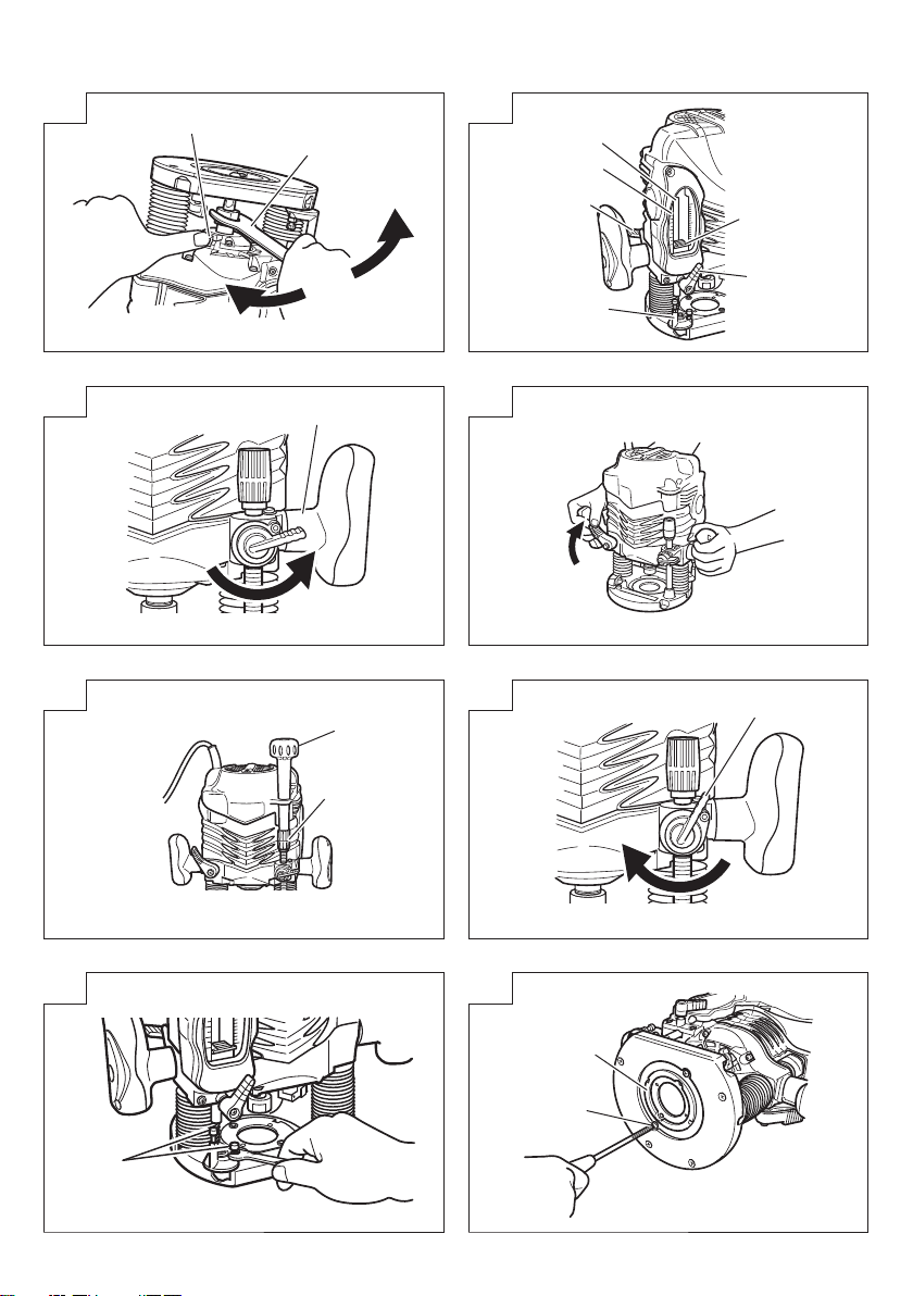
(1) Template guide adapter
1Loosen the 2 template guide adapter screws, so
that the template guide adapter can be moved. (Fig. 8)
2Insert the centering gauge through the hole in the
template guide adapter and into the collet chuck. (Fig. 9)
3Tighten the collet chuck by hand.
4Tighten the template guide adapter screws, and
pull out the centering gauge.
(2) Template guide
Use the template guide when employing a template
for producing a large quantity of identically shaped
products. (Fig. 10)
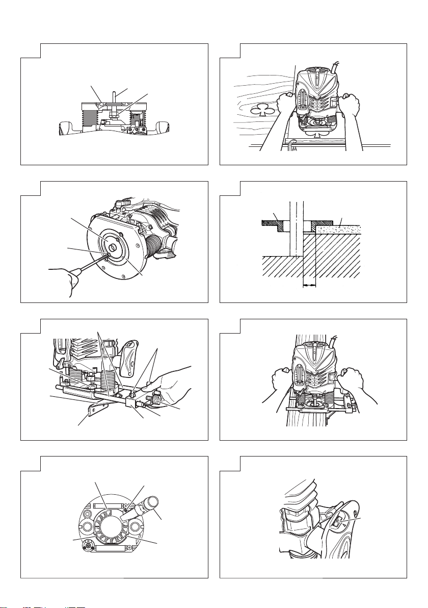
As shown in Fig. 11, to install insert template
guide in center hole in template guide adapter with
2 accessory screws.
A template is a profiling mold made of plywood
or thin lumber. When making a template, pay
particular attention to the matters described below
and illustrated in Fig. 12.
When using the router along the interior plane
of the template, the dimensions of the finished
product will be less than the dimensions of the
template by an amount equal to dimension “A”, the
difference between the radius of the template guide
and the radius of the bit. The reverse is true when
using the router along the exterior of the template.
(3) Straight guide
Use straight guide for chamfering and groove
cutting along the materials side.
1Insert the guide bar into the hole in the bar holder,
then lightly tighten the 2 wing bolts (A) on top of
the bar holder.
2Insert the guide bar into the hole in the base, then
firmly tighten the wing bolt (A).
3Make minute adjustments of the dimensions
between the bit and the guide surface with the
feed screw, then firmly tighten the 2 wing bolts (A)
on top of the bar holder and the wing bolt (B) that
secures the straight guide.
4As shown in Fig. 14, securely attach the bottom
of the base to processed surface of the materials.
Feed the router while keeping the guide plane on
the surface of the materials.
(4) Dust guide and Dust guide adapter (Fig. 15)
Your router is equipped with dust guide and a dust
guide adapter.
1Match the 2 grooves on the base and insert the 2
dust guide tabs in holes located in the base side
from the top. Tighten the dust guide with a screw.
The dust guide diverts cutting debris away from
the operator and directs the discharge in a
consistent direction.
2By fitting the dust guide adapter into the dust guide
cutting debris discharge vent, the dust extractor can
be attached.
4. Adjusting the rotation speed (Model M12V2
only)
The M12V2 has an electronic control system that
allows stepless rpm changes.
As shown in Fig. 16, dial position “1” is for
minimum speed, and position “ 6” for maximum
speed.
5. Removing the spring
The springs within the column of the router can be
removed. Doing so will eliminate spring resistance
and allows easy adjustment of cutting depth when
attaching the router stand.
(1) Loosen the 4 sub base screws, and remove the
sub base.
(2) Loosen the stopper bolt and remove it, so the
spring can be removed. (Fig. 17)
CAUTION
Remove the stopper bolt with the main unit (router)
fixed at its maximum height.
Removing the stopper bolt with the unit in a
shortened condition may cause the stopper bolt
and spring to be discharged and cause injury.
6. Cutting
CAUTION
○Wear eye protection when operating this tool.
○Keep your hands, face and other body parts away
from the bits and any other rotating parts, while
operating the tool.
(1) As shown in Fig. 18, remove the bit from the work
pieces and press the switch lever up to the ON
position. Do not start cutting operation until the bit
has reached full rotating speed.
(2) The bit rotates clockwise (arrow direction indicated
on the base). To obtain maximum cutting
effectiveness, feed the router in conformance with
the feed directions shown in Fig. 19.
NOTE
If a worn bit is used to make deep grooves, a high
pitched cutting noise may be produced.
Replacing the worn bit with a new one will
eliminate the high pitched noise.
USING THE OPTIONAL ACCESSORIES
Trimmer Guide (Fig. 20):
Use the trimmer guide for trimming or chamfering.
Attach the trimmer guide to the bar holder as
shown in Fig. 21.
After aligning the roller to the appropriate position,
tighten the two wing bolts (A) and the other two
wing bolts (B). Use as shown in Fig. 22.
MAINTENANCE AND INSPECTION
1. Oiling
To ensure smooth vertical movement of the router,
occasionally apply a few drops of machine oil to
the sliding portions of the columns and end bracket.
2. Inspecting the mounting screws
Regularly inspect all mounting screws and ensure
that they are properly tightened. Should any of
the screws be loose, retighten them immediately.
Failure to do so could result in serious hazard.
3. Maintenance of the motor
The motor unit winding is the very “heart” of the
power tool.
Exercise due care to ensure the winding does not
become damaged and/or wet with oil or water.
4. Inspecting the carbon brushes
For your continued safet y and elec tr ic al shock
protection, carbon brush inspection and replacement
on this tool should ONLY be performed by a
HiKOKI AUTHORIZED SERVICE CENTER.
000BookM12V2Asia.indb10000BookM12V2Asia.indb10 2019/01/2115:24:312019/01/2115:24:31

11
English
5. Replacing supply cord
If the supply cord of Tool is damaged, the Tool
must be returned to HiKOKI Authorized Service
Center for the cord to be replaced.
6. Service parts list
A: Item No.
B: Code No.
C: No. Used
D: Remarks
CAUTION
Repair, modification and inspection of HiKOKI
Power Tools must be carried out by a HiKOKI
Authorized Service Center.
This Parts List will be helpful if presented with the
tool to the HiKOKI Authorized Service Center when
requesting repair or other maintenance.
In the operation and maintenance of power tools,
the safety regulations and standards prescribed in
each country must be observed.
MODIFICATION
HiKOKI Power Tools are constantly being improved
and modified to incorporate the latest technological
advancements.
Accordingly, some parts (i.e. code numbers and/or
design) may be changed without prior notice.
NOTE
Due to HiKOKI’s continuing program of research and
development, the specifications herein are subject to
change without prior notice.
000BookM12V2Asia.indb11000BookM12V2Asia.indb11 2019/01/2115:24:312019/01/2115:24:31

12
Español
ADVERTENCIAS DE SEGURIDAD GENERAL
DE LA HERRAMIENTA ELÉCTRICA
ADVERTENCIA
Lea todas las instrucciones y advertencias de
seguridad.
Si no se siguen las advertencias e instrucciones,
podría producirse una descarga eléctrica, un incendio
o daños graves.
Guarde todas las advertencias e instrucciones
para futura referencia.
El término “herramienta eléctrica” en las advertencias
hace referencia a la herramienta eléctrica que
funciona con la red de suministro (con cable) o a
la herramienta eléctrica que funciona con pilas (sin
cable).
1) Seguridad del área de trabajo
a) Mantenga la zona de trabajo limpia y bien
iluminada.
Las zonas desordenadas y oscuras pueden
provocar accidentes.
b) No utilice las herramientas eléctricas en
entornos explosivos como, por ejemplo, en
presencia de líquidos inflamables, gases o
polvo.
Las herramientas eléctricas crean chispas que
pueden hacer que el polvo desprenda humo.
c) Mantenga a los niños y transeúntes alejados
cuando utilice una herramienta eléctrica.
Las distracciones pueden hacer que pierda el
control.
2) Seguridad eléctrica
a) Los enchufes de las herramientas eléctricas
tienen que ser adecuados a la toma de corriente.
No modifique el enchufe.
No utilice enchufes adaptadores con
herramientas eléctricas conectadas a tierra.
Si no se modifican los enchufes y se utilizan
tomas de corriente adecuadas se reducirá el
riesgo de descarga eléctrica.
b) Evite el contacto corporal con superficies
conectadas a tierra como tuberías, radiadores
y frigoríficos.
Hay mayor riesgo de descarga eléctrica si su
cuerpo está en contacto con el suelo.
c) No exponga las herramientas eléctricas a la
lluvia o a la humedad.
La entrada de agua en una herramienta eléctrica
aumentará el riesgo de descarga eléctrica.
d) No utilice el cable incorrectamente. No
utilice el cable para transportar, tirar de la
herramienta eléctrica o desenchufarla.
Mantenga el cable alejado del calor, del
aceite, de bordes afilados o piezas móviles.
Los cables dañados o enredados aumentan el
riesgo de descarga eléctrica.
e) Cuando utilice una herramienta eléctrica
al aire libre, utilice un cable prolongador
adecuado para utilizarse al aire libre.
La utilización de un cable adecuado para
usarse al aire libre reduce el riesgo de
descarga eléctrica.
f) Si no se puede evitar el uso de una
herramienta eléctrica en un lugar húmedo,
utilice un suministro protegido mediante un
dispositivo de corriente residual (RCD).
El uso de un RCD reduce el riesgo de
descarga eléctrica.
3) Seguridad personal
a) Esté atento, preste atención a lo que hace y
utilice el sentido común cuando utilice una
herramienta eléctrica.
No utilice una herramienta eléctrica cuando
esté cansado o esté bajo la influencia de
drogas, alcohol o medicación.
La distracción momentánea cuando utiliza
herramientas eléctricas puede dar lugar a
importantes daños personales.
b) Utilice un equipo de protección personal.
Utilice siempre una protección ocular.
El equipo de protección como máscara para
el polvo, zapatos de seguridad antideslizantes,
casco o protección auditiva utilizado en las
situaciones adecuadas reducirá las lesiones
personales.
c) Evite un inicio involuntario. Asegúrese
de que el interruptor esté en “off” antes
de conectar la herramienta a una fuente
de alimentación o batería, cogerla o
transportarla.
El transporte de herramientas eléctricas con
el dedo en el interruptor o el encendido de
herramientas eléctricas con el interruptor
encendido puede provocar accidentes.
d) Retire las llaves de ajuste antes de encender
la herramienta eléctrica.
Si se deja una llave en una pieza giratoria
de la herramienta eléctrica podrían producirse
daños personales.
e) No se extralimite. Mantenga un equilibrio
adecuado en todo momento.
Esto permite un mayor control de la herramienta
eléctrica en situaciones inesperadas.
f) Vístase adecuadamente. No lleve prendas
sueltas o joyas. Mantenga el pelo, la ropa y
los guantes alejados de las piezas móviles.
La ropa suelta, las joyas y el pelo largo pueden
pillarse en las piezas móviles.
g) Si se proporcionan dispositivos para la conexión
de extracción de polvo e instalaciones de
recogida, asegúrese de que están conectados y
se utilizan adecuadamente.
La utilización de estos dispositivos puede
reducir los riesgos relacionados con el polvo.
4) Utilización y mantenimiento de las herramientas
eléctricas
a) No fuerce la herramienta eléctrica. Utilice
la herramienta eléctrica correcta para su
aplicación.
La herramienta eléctrica correcta trabajará
mejor y de forma más segura si se utiliza a la
velocidad para la que fue diseñada.
b) No utilice la herramienta eléctrica si el
interruptor no la enciende y apaga.
Las herramientas eléctricas que no pueden
controlarse con el interruptor son peligrosas y
deben repararse.
c) Desconecte el enchufe de la fuente eléctrica
antes de hacer ajustes, cambiar accesorios
o almacenar herramientas eléctricas.
Estas medidas de seguridad preventivas reducen
el riesgo de que la herramienta eléctrica se
ponga en marcha accidentalmente.
000BookM12V2Asia.indb12000BookM12V2Asia.indb12 2019/01/2115:24:312019/01/2115:24:31

Español
13
d) Guarde las herramientas eléctricas que no
se utilicen para que no las cojan los niños
y no permita que utilicen las herramientas
eléctricas personas no familiarizadas con las
mismas o con estas instrucciones.
Las herramientas eléctricas son peligrosas si
son utilizadas por usuarios sin formación.
e) Mantenimiento de las herramientas eléctricas.
Compruebe si las piezas móviles están mal
alineadas o unidas, si hay alguna pieza
rota u otra condición que pudiera afectar al
funcionamiento de las herramientas eléctricas.
Si la herramienta eléctrica está dañada,
llévela a reparar antes de utilizarla.
Se producen muchos accidentes por no realizar
un mantenimiento correcto de las herramientas
eléctricas.
f) Mantenga las herramientas de corte afiladas
y limpias.
Las herramientas de corte correctamente
mantenidas con los bordes de corte afilados
son más fáciles de controlar.
g) Utilice la herramienta eléctrica, los accesorios
y las brocas de la herramienta, etc., de
acuerdo con estas instrucciones y de la
manera adecuada para el tipo de herramienta
eléctrica, teniendo en cuenta las condiciones
laborales y el trabajo que se va a realizar.
La utilización de la herramienta eléctrica para
operaciones diferentes a pretendidas podría dar
lugar a una situación peligrosa.
5) Revisión
a) Lleve su herramienta a que la revise un
experto cualificado que utilice sólo piezas
de repuesto idénticas.
Esto garantizará el mantenimiento de la
seguridad de la herramienta eléctrica.
PRECAUCIÓN
Mantenga a los niños y a las personas
enfermas alejadas.
Cuando no se utilicen, las herramientas deben
almacenarse fuera del alcance de los niños y
de las personas enfermas.
ADVERTENCIAS DE SEGURIDAD DE LA
FRESADORA
1. Sostenga la herramienta eléctrica por las
superficies de agarre, ya que el accesorio de
corte puede entrar en contacto con su propio
cable.
Al cortar un cable con corriente pueden quedar
expuestas partes metálicas de la herramienta
eléctrica y provocar descargas eléctricas al
operario.
2. Use abrazaderas u otra cualquier forma
práctica para fi jar y apoyar el elemento de
trabajo sobre una plataforma estable.
Sostener el elemento de trabajo con la mano o
contra su cuerpo no crea un entorno estable y
podría derivar en la pérdida del control.
3. Cuando se comienza la operación con una mano
es inestable y tambien peligrosa. Asegurarse de
que ambos asideros están agarrados firmemente
durante la operación.
4. Cuando la broca está ardiente después de
la operación evite el contacto con las manos
desnudas hacia la broca.
ESPECIFICACIONES
Modelo M12V2 M12SA2
Voltaje (por áreas)* (110 V, 120 V, 220 V, 230 V, 240 V)
Acometida* 2000 W 1700 W
Capacidad de pinza 12 mm o 1/2"
Velocidad de marcha en vacío 8000 – 22000 /min 22000 /min
Carrera cuerpo central 65 mm
Peso (sin cable y accesorios estándar) 6,3 kg 6,2 kg
* Verificar indenfectiblemente los datos de la placa de características de la máquina, pues varían de acuerdo
al país de destino.
ACCESORIOS ESTANDAR
(1) Guía derecha..............................................................1
(2) Sujetador de barra .....................................................1
Barra de guía..............................................................2
Tornillo de alimentación.............................................1
Pasador de palomilla .................................................1
(3) Guía de polvo .............................................................1
(4) Adaptador de guía de polvo......................................1
(5) Guía patrón.................................................................1
(6) Adaptador de guía patrón..........................................1
(7) Indicador de centrado................................................1
(8) Perilla ..........................................................................1
(9) Llave para tuercas .....................................................1
(10) Boquilla de mordazas de 8 mm o 1/4” ....................1
(11) Perno de aletas (A) ..................................................4
(12) Resorte de seguridad ...............................................2
Los accesorios normales están sujetos a cambio sin
previo aviso.
000BookM12V2Asia.indb13000BookM12V2Asia.indb13 2019/01/2115:24:312019/01/2115:24:31

14
Español
ACCESORIOS FACULTATIVOS
– de venda por separado
(1) Guía de patrón
Parte inferior de la
base secundaria
ABC
16,5 mm 18 mm
4,5 mm
18,5 mm 20 mm
25,5 mm 27 mm
28,5 mm 30 mm
(2) Manguito de cierre
d
D
20 mm
Dd
Forma del manguito de cierre
12 mm
6 mm no hueco
3/8" 1 hueco
1/2"
3/8" 2 huecos
10 mm no hueco
(3) Conjunto guía recortadora (Fig. 20)
(4) Adaptador de guía de plantilla (B)
Para el producto de Trend.
Los accesorios facultativos están sujetos a cambio sin
previo aviso.
APLICACIONES
○Trabajos de madera centrados en ranuradora y
biselados.
ANTES DE LA PUESTA EN MARCHA
1. Alimentación
Asegurarse de que la alimentación de red que
ha de ser utilizada responda a las exigencias
de corriente especificadas en la placa de
características del producto.
2. Conmutador de alimentación
Asegurarse de que el conmutador de alimentación
esté en la posición OFF (desconectado). Si la
clavija está conect ada en la caja del enchufe
mientras el conmutador de alimentación esté
en pocisión ON (conectado) las herramientas
eléctricas empezarán a trabajar inmediatamente,
provocando un serio accidente.
3. Cable de prolongación
Cuando está alejada el área de trabajo de la red
de alimentación, usar un cable de prolongación de
un grosor y potencia nominal suficiente. El cable
de prolongación debe ser mantenido lo más corto
posible.
4. RCD (dispositivo de corriente residual)
Se recomienda utilizar en todo momento un
dispositivo de corriente residual con una corriente
residual nominal de 30 mA o menos.
INSTALACIÓN Y DESINSTALACIÓN DE
BROCAS
ADVERTENCIA
Asegúrese de apagar y desconectar la clavija del
receptáculo para evitar problemas graves.
1. Instalación de brocas
(1) Limpie e inserte el cuerpo de la broca en la
boquilla de mordazas hasta que el cuerpo toque el
fondo y luego vuelva a sacarlo unos 2 mm.
(2) Con la broca insertada y presionando el pasador
de cierre que sujeta el eje del inducido, use la
llave para tuercas de 23 mm para apretar bien la
boquilla de mordazas en el sentido de las agujas
del reloj (visto desde debajo de la fresadora). (Fig. 1)
PRECAUCIÓN
○Asegúrese de que la boquilla de mordazas está bien
sujeta después de insertar la broca. De lo contrario,
se producirán daños en la boquilla de mordazas.
○Asegúrese de que el pasador de cierre no está
inser tado en el eje del inducido tras apretar la
boquilla de mordazas. De lo contrario, se producirán
daños en la boquilla de mordazas, en el pasador
de cierre y en el eje del inducido.
(3) Al usar una broca con un cuerpo de 8 mm de
diámetro, sustituya la boquilla de mordazas equipada
por la broca de cuerpo de 8 mm de diámetro que
se suministra como accesorio estándar.
2. Desinstalación de brocas
Cuando desinstala brocas, hágalo siguiendo los
pasos de instalación, pero en orden inverso.
PRECAUCIÓN
Asegúrese de que el pasador de cierre no está
inser tado en el eje del inducido tras apretar la
boquilla de mordazas. De lo contrario, se producirán
daños en la boquilla de mordazas, en el pasador
de cierre y en el eje del inducido.
COMO USAR LA FRESADORA
1. Ajuste de la profundidad de corte (Fig. 2)
(1) Coloque la herramienta sobre una superficie de
madera plana.
(2)Gire la palanca de ajuste rápido en sentido
contrario a las agujas del reloj hasta que se
detenga la palanca de ajuste rápido. (Fig. 3)
000BookM12V2Asia.indb14000BookM12V2Asia.indb14 2019/01/2115:24:312019/01/2115:24:31

Español
15
(3) Gire el bloque del dispositivo de ajuste de tal forma
que la sección a la que no está fijado el tornillo
de ajuste de la profundidad de corte en un bloque
del dispositivo de ajuste toque el fondo del polo
del dispositivo de ajuste. Suelte la perilla de cierre
del polo de tal forma que el polo del dispositivo
de ajuste entre en contacto con el bloque del
dispositivo de ajuste.
(4) Afloje la palanca de cierre y presione el cuerpo
de la herramienta hasta que la broca toque la
superficie plana. Apriete la palanca de cierre en
este punto. (Fig. 4)
(5) Apriete la perilla de cierre del polo. Alinee el indicador
de profundidad con la graduación “0” de la escala.
(6) Afloje la perilla de cierre del polo y súbala hasta
que el indicador se alinee con la graduación que
indica la profundidad de corte deseada. Apriete la
perilla de cierre del polo.
(7) Afloje la palanca de cierre y presione el cuerpo
de la herramienta hacia abajo hasta que el bloque
del dispositivo de ajuste alcance la profundidad de
corte deseada.
La fresadora permite ajustar con precisión la
profundidad del corte.
(1) Fije la perilla en el control de ajuste preciso.
(2) Gire la palanca de ajuste rápido en el sentido de
las agujas del reloj hasta que la palanca de ajuste
rápido se detenga con el tornillo del dispositivo de
ajuste. (Fig. 5)
Si la palanca de ajuste rápido no se detiene con
el tornillo del dispositivo de ajuste, significa que el
tornillo no está bien instalado.
Si ocurre esto, afloje ligeramente la palanca de
cierre y presione con fuerza contra la unidad
(fresadora) desde arriba y gire la palanca de ajuste
rápido una vez más después de haber instalado
bien el tornillo.
(3) La profundidad de corte se puede ajustar cuando
la palanca de cierre se afloje girando el control
de ajuste preciso. Al girar el control de ajuste
preciso en sentido contrario a las agujas del reloj
se produce un corte más superficial, mientras que
si se gira en el sentido de las agujas del reloj se
produce un corte más profundo.
PRECAUCIÓN
Asegúrese de que la palanca de cierre esté
apretada tras ajustar con precisión la profundidad
de corte. De lo contrario, se producirán daños en
la palanca de ajuste rápido.
2. Bloque del dispositivo de ajuste (Fig. 6)
Los dos tornillos de ajuste de la profundidad de
corte fijados al bloque del dispositivo de ajuste se
pueden ajustar para establecer al mismo tiempo
tres profundidades de corte distintas. Utilice una
llave para tuercas para apretar las tuercas de tal
forma que los tornillos de ajuste de la profundidad
de corte no se aflojen en este momento.
3. Cómo guiar la fresadora
ADVERTENCIA
Asegúrese de apagar y desconectar la clavija del
receptáculo para evitar problemas graves.
(1) Adaptador de guía patrón
1Afloje los dos tornillos del adapt ador de guía
patrón, de tal forma que el adaptador de guía
patrón se pueda mover. (Fig. 8)
2Inser te el indicador de centrado a través del
orificio del adapt ador de guía patrón y en la
boquilla de mordazas. (Fig. 9)
3Apriete la boquilla de mordazas con la mano.
4Apriete los tornillos del adaptador de guía patrón y
saque el indicador de centrado.
(2) Guía patrón
Utilice la guía patrón cuando use un patrón para
hacer una gran cantidad de productos con la
misma forma. (Fig. 10)
Tal y como se muestra en la Fig. 11, inserte la
guía patrón en el orificio central del adaptador de
guía patrón con 2 tornillos accesorios.
Un patrón es un molde de perfilado hecho de
contrachapado o madera fina. Al realizar un patrón,
preste especial atención a los aspectos descritos a
continuación e ilustrados en la Fig. 12.
Cuando utilice la fresadora por el plano interior de
la plantilla, las dimensiones del producto acabado
serán inferiores a las dimensiones del patrón en
una cantidad igual a la dimensión “A”, la diferencia
entre el radio de la guía patrón y el radio de la
broca. Lo mismo ocurre a la inversa si se usa la
fresadora por el exterior del patrón.
(3) Guía derecha
Use la guía derecha para biselar y acanalar el
borde de los materiales.
1Inserte la barra de guía en el orificio del sujetador
de barra y luego apriete los 2 pernos de aletas (A)
de la parte superior del sujetador de barra.
2Inserte la barra de guía en el orificio de la base y
luego apriete bien el perno de aletas (A).
3Realice ajustes mínimos de las dimensiones entre
la broca y la superficie de la guía con el tornillo
de alimentación, y luego apriete con fuerza los
dos pernos de aletas (A) de la parte superior del
sujetador de barra y el perno de aletas (B) que
fija la guía derecha.
4Tal y como se muestra en la Fig. 14, fije bien la
parte inferior de la base a la superficie procesada
de los materiales. Alimente la fresadora mientras
mantiene la guía plana con respecto a la superficie
de los materiales.
(4) Guía de polvo y adaptador de guía de polvo (Fig. 15)
La fresadora está equipada con una guía de polvo
y un adaptador de guía de polvo.
1Haga coincidir las 2 ranuras de la base e inserte
las dos pestañas de la guía de polvo en los
orificios situados en la parte de la base desde
arriba. Apriete la guía de polvo con un tornillo.
La guía de polvo evita que los restos del proceso
de corte salten hacia el operador y dirige la
descarga en una dirección constante.
2Instalando el adaptador de guía de polvo en la
abertura de descarga de restos de corte de la
guía de polvo, se puede fijar el extractor de polvo.
4. Ajuste de la velocidad de rotación (Modelo
M12V2 solamente)
El modelo M12V2 tiene un sistema de control
electrónico que permite el cambio contínuo de las
rpm. (revoluciones por minuto).
Como se muestra en la Fig. 16, la posición “1” del
dial corresponde a la velocidad minima, y “6” a la
máxima.
000BookM12V2Asia.indb15000BookM12V2Asia.indb15 2019/01/2115:24:312019/01/2115:24:31

16
Español
5. Desinstalación del muelle
Los muelles del interior de la columna de la
fresadora se pueden desmontar. Al hacerlo, se
eliminará la resistencia del muelle y se permitirá
un ajuste más sencillo de la profundidad de corte
al fijar el soporte de la fresadora.
(1) Afloje los cuatro tornillos de la subbase y retire la
subbase.
(2) Afloje el perno del dispositivo de ajuste y retírelo, de
tal forma que el muelle se pueda retirar. (Fig. 17)
PRECAUCIÓN
Retire el perno del dispositivo de ajuste con la
unidad principal (fresadora) fijada en su altura
máxima.
Al retirar el perno del dispositivo de ajuste con
la unidad en un estado acortado, se puede soltar
el perno del dispositivo de ajuste y el muelle, y
producir lesiones.
6. Cortar
PRECAUCIÓN
○Utilice algún tipo de protección ocular cuando
utilice esta herramienta.
○Mantenga las manos, la cara y otras partes del
cuerpo alejadas de las brocas y de cualquier otra
pieza giratoria mientras utiliza la herramienta.
(1) Como se muestra en la Fig. 18 separe la broca
del material y empuje la palanca del interruptor
hacia arriba hasta la posición ON. No comience
la operación de cor te hasta que la broca haya
alcanzado la velocidad de rotación completa.
(2) La broca gira hacia la derecha (sentido de in
flecha indicada en la base). Para lograr la máxima
efectividad del corte, haga avanzar la fresadora
vertical de acuerdo con los sentidos de avance
mostrados en la Fig. 19.
OBSERVACIÓN
Si se utiliza una broca gastada para hacer ranuras
profundas, puede producirse un ruido de corte
elevado.
La sustitución de la broca gastada por una nueva
eliminará el ruido elevado.
UTILIZACION DE LOS ACCESORIOS
OPCIONALES
Guía recortadora (Fig. 20):
Empleo de la guía de recorte para recortar o biselar.
Instale la guía de recorte en el soporte de barra
como muestra en la Fig. 21. Después de alinear
el rodillo en la posición apropiada, apriete los dos
pernos de aletas (A) y los otros dos pemos de aletas (A)
y los otros dos pemos de aletas (B). Utilice como se
muestra en la Fig. 22.
MANTENIMIENTO E INSPECCION
1. Lubrificado
Para asegurar un movimiento vertical suave de la
fresadora, aplicar ocasionalmente unas gotas de
aceite de máquina a las partes corredizas de las
columnas y del listón final.
2. Inspeccionar los tornillos de montaje
Regularmente inspeccionar todos los tornillos de
montaje y asegurarse de que estén apretados
firmemente. Si cualquier tornillo estuviera suelto,
volver a apretarlo inmediatamente. El no hacer
esto provocaría un riesgo serio.
3. Maintenance of the motor
La unidad de bobinado del motor es el verdadero
“corazón” de las herramientas eléctricas.
Prestar el mayor cuidado a asegurarse de que el
bobinado no se dañe y/o se humedezca con aceite
o agua.
4. Inspección de las escobillas
Por motivos de seguridad contra descargas
eléctricas, la inspección y el reemplazo de las
escobillas deberán realizarse SOL AMENTE en
un CENTRO DE SERVICIO AUTORIZADO POR
HiKOKI.
5. Reemplazo del cable de alimentación
Si el cable de alimentación de la herramienta está
dañado, envíe la herramienta al Centro de Servicio
Autorizado de HiKOKI para que le cambien el
cable de alimentación.
6. Lista de repuestos
A: N°. ítem
B: N°. código
C: N°. usado
D: Observaciones
PRECAUCIÓN
La reparación, modificación e inspección de las
herramientas eléctricas HiKOKI deben ser realizadas
por un Centro de Servicio Autorizado de HiKOKI.
Esta lista de repuestos será de utilidad si es
presentada junto con la herramienta al Centro de
Servicio Autorizado de HiKOKI, para solicitar la
reparación o cualquier otro tipo de mantenimiento.
En el manejo y el mantenimiento de las
herramientas eléctricas, se deberán observar las
normas y reglamentos vigentes en cada país.
MODIFICACIONES
HiKOKI Power Tools introduce constantemente
mejoras y modificaciones para incorporar los
últimos avances tecnológicos.
Por consiguiente, algunas partes (por ejemplo,
números de códigos y/o diseño) pueden ser
modificadas sin previo aviso.
OBSERVACIÓN
Debido al programa continuo de investigación y
desarrollo de HiKOKI estas especificaciones están
sujetas a cambio sin previo aviso.
000BookM12V2Asia.indb16000BookM12V2Asia.indb16 2019/01/2115:24:312019/01/2115:24:31

中國語
17
一般安全規則
警告
閱讀所有安全警告說明
未遵守警告與說明可能導致電擊、火災及或其他嚴
重傷害。
請妥善保存所有警告與說明,以供未來參考之用。
「電動工具」一詞在警告中,係指電源操作(有線)
之電動工具或電池操作(無線)之電動工具。
1) 工作場所安全
a) 保持工作場所清潔及明亮。
雜亂及昏暗區域易發生意外。
b) 勿在易產生爆炸之環境中操作,譬如有易燃液
體、瓦斯或粉塵存在之處。
電動工具產生火花會引燃粉塵或煙氣。
c)
當操作電動工具時,保持兒童及過往人員遠離。
分神會讓你失去控制。
2) 電氣安全
a) 電動工具插頭必須與插座配合,絕不可以任何
方法修改插頭,且不得使用任何轉接插頭於有
接地之電動工具。
不修改插頭及所結合之插座可減少電擊。
b) 避免身體接觸到接地面諸如管子、散熱器、爐
灶及冰箱。
如果你的身體接地或搭地,會增加電擊的危險。
c) 勿讓電動工具淋雨或曝露在潮濕的環境下。
電動工具進水會增加電繫的危險。
d) 勿濫用電源線。絕勿使用電源線去纏繞、拖拉
電動工具或拔插頭,保持電源線遠離熱氣、油
氣、尖角或可動零件。
損壞或纏繞的電源線會增加電繫之危險。
e) 電動工具在室外操作時要使用一適合室外用的
延長線。
使用合適之室外用延長線會減少電擊的危險。
f) 若無法避免在潮濕地區操作電動工具,請使用
以殘餘電流裝置 (RCD) 保護的電源。
使用 RCD 可降低觸電危險。
3) 人員安全
a) 保持機警,注意你正在做什麼,並運用普通常
識操作電動工具。
當你感到疲勞或受藥品、酒精或醫療影響時,
勿操作電動工具。
操作中瞬間的不注意可能造成人員嚴重的傷
害。
b) 使用個人防護裝備,經常配戴安全眼鏡。
配戴防塵口罩、防滑安全鞋、硬帽等防護裝
備,或在適當情況下使用聽覺防護,可減少人
員傷害。
c) 防止意外啟動。在連接電源及或電池組、拿
起或攜帶工具前,請確認開關是在「off」(關
閉)的位置。
以手指放在開關握持電動工具,或在電動工具
的開關於“on”的狀況下插上插頭,都會導致
意外發生。
d) 在將電動工具啟動前,先卸下任何調整用鑰匙
或扳手。
扳手或鑰匙遺留在電動工具的轉動部位時,可
能導致人員傷害。
e)
身體勿過度伸張,任何時間要保持站穩及平衡。
以便在不預期的狀態下,能對電動工具有較好
的控制。
f) 衣著要合宜,別穿太鬆的衣服或戴首飾。
保持你的頭髮、衣服及手套遠離轉動部位。
寬鬆的衣服、手飾及長髮會被捲入轉動部位。
g) 如果裝置要用於粉塵抽取及集塵設施,要確保
其連接及正當使用。
使用此類裝置能減少與粉塵有關之危害。
4) 電動工具之使用及注意事項
a) 勿強力使用電動工具,使用正確之電動工具為
你所需。
正確使用電動工具會依其設計條件使工作做得
更好更安全。
b) 如果開關不能轉至開及關的位置,勿使用電動
工具。
任何電動工具不能被開關所控制是危險的,必
須要修理。
c) 在做任何調整、更換配件或收存電動工具時,
要將插頭與電源分開,且/或將電池從電動工
具中取出。
此種預防安全措施可減少意外開啟電動機之危
險。
d) 收存停用之電動工具,遠離兒童,且不容許不
熟悉電動工具或未瞭解操作電動工具說明書的
人操作電動工具。
在未受過訓練的人手裡,電動工具極為危險。
e) 保養電動工具,檢核是否有可動零件錯誤的結
合或卡住、零件破裂及可能影響電動工具操作
的任何其他情形。
電動工具如果損壞,在使用前要修好。許多意
外皆肇因於不良的保養。
f) 保持切割工具銳利清潔。
適當的保養切割工具,保持銳利之切削鋒口,
可減少卡住並容易控制。
g) 按照說明書使用電動工具、配件及刀具等,使
用特殊型式之電動工具時要考量工作條件及所
執行之工作。
使用電動工具未如預期用途之操作時,會導致
危害。
000BookM12V2Asia.indb17000BookM12V2Asia.indb17 2019/01/2115:24:312019/01/2115:24:31

18
中國語
5) 維修
a) 讓你的電動工具由合格修理人員僅使用相同的
維修零件更換。
如此可確保電動工具的安全得以維持。
注意事項
不可讓孩童和體弱人士靠近工作場所。
應將不使用的工具存放在孩童和體弱人士伸手不及的
地方。
刨槽機安全警告
1. 由於切刀可能會接觸到其自身的電線,因此請握
住電動工具的絕緣握持面。
切割到「通電」的電線可能會使電動工具露出的
金屬零件「通電」,而造成操作者觸電。
2. 使用夾具或其他可實施的方式將工件固定並支撐
在穩定的平台上。
用手握住工件或用身體抵住工件會使其不穩定,
並可能導致失去控制。
3. 單手作業不穩定且非常危險。請務必在作業期間
緊握雙柄。
4. 作業開始後鑽頭會立即發燙。任何情況下都切勿
用手觸摸鑽頭。
規 格
型號 M12V2 M12SA2
電壓(按地區)* (110 V, 120 V, 220 V, 230 V, 240 V)
輸入功率* 2000 W 1700 W
夾盤夾持直徑 12 mm 或 1/2"
無負荷速度 8000
-
22000 轉/分 22000 轉/分
機身長度 65 mm
重量(不含線纜和標準附件)6.3 kg 6.2 kg
* 當須改變地區時應檢查產品上的銘牌。
標準附件
(1) 直導架 ............................................................ 1
(2) 導杆固定器 ..................................................... 1
導杆 ................................................................2
進給螺杆......................................................... 1
碟形螺栓......................................................... 1
(3) 碎屑導架......................................................... 1
(4) 碎屑導架附加器 .............................................. 1
(5) 模板導架......................................................... 1
(6) 模板導架附加器 .............................................. 1
(7) 定心規 ............................................................ 1
(8) 旋鈕 ................................................................1
(9) 扳手 ................................................................1
(10) 8 ㎜ 或 1/4" 夾盤 ............................................ 1
(11) 碟形螺栓 (A) ................................................... 4
(12) 固定彈簧......................................................... 2
標準附件可能不預先通告而徑予更改。
選購附件(分開銷售)
(1) 模板導架
底座底部
ABC
16.5 mm 18 mm
4.5 mm
18.5 mm 20 mm
25.5 mm 27 mm
28.5 mm 30 mm
000BookM12V2Asia.indb18000BookM12V2Asia.indb18 2019/01/2115:24:312019/01/2115:24:31

中國語
19
(2) 夾盤
d
D
20 mm
D d 夾盤架形狀
12 mm
6 mm 無槽
3/8" 1槽
1/2"
3/8" 2槽
10 mm 無槽
(3) 修整器導架 (圖 20)
(4) 模板導架附加器 (B)
適用於Trend產品。
選購附件可能不預先通告而徑予更改。
用 途
○ 以開槽和削角為主的木工作業。
作業之前
1. 電源
確認所使用的電源與工具銘牌上標示的規格是否
相符。
2. 電源開關
確認電源開關是否切斷。若電源開關接通,則插
頭插入電源插座時電動工具將出其不意地立刻轉
動,從而招致嚴重事故。
3. 延伸線纜
若作業場所移到離開電源的地點,應使用容量足
夠、鎧裝合適的延伸線纜,並且要盡可能地短
些。
4. RCD
使用殘餘電流裝置時,建議採 30 mA 以下的額定
殘餘電流。
鑽頭的安裝和拆卸
警告
請務必關閉電源,並將插頭從插座上拔下,以免造
成嚴重事故。
1. 安裝鑽頭
(1) 清潔鑽頭長柄,然後將其插入夾盤直至長柄到達
底端,再將其往外拉出2 mm左右。
(2) 插入鑽頭後將鎖銷壓入抵住電樞軸,然後用23 mm
扳手以逆時針方向將夾盤牢固地旋緊(從刨槽機
下方看)。(圖1)
注意﹕
○ 務必在插入鑽頭後牢固地旋緊夾盤。否則會損
壞夾盤。
○ 在旋緊夾盤後確認鎖銷未插入電樞軸。否則會
損壞夾盤、鎖銷和電樞軸。
(3) 使用直徑8 mm的長柄鑽頭時,請用其專用夾盤
(標準附件中提供)換下已裝上的夾盤。
2. 拆卸鑽頭
拆卸鑽頭時,按安裝鑽頭的相反步驟進行。
注意﹕
在旋緊夾盤後確認鎖銷未插入電樞軸。否則會損壞
夾盤、鎖銷和電樞軸。
如何使用刨槽機
1. 調整切割深度。(圖 2)
(1) 將工具放到水準的木頭平面上。
(2) 以逆時針方向旋轉快速調整杆,直至其停住。
(圖 3)
(3) 旋轉止動塊,直至止動塊上未安裝有切割深度設
定螺絲的部分觸及止動杆的底端。旋松杆固定旋
鈕,使止動杆可觸及止動塊。
(4) 旋松固定杆,然後壓入機身直至鑽頭觸及平面。
在該點旋緊固定杆。(圖 4)
(5) 旋緊杆固定旋鈕。將深度指針對準刻度片上的
“0”。
(6) 旋松杆固定旋鈕,然後提高至指標對準所需切割
深度的刻度。旋緊杆固定旋鈕。
(7) 旋松固定杆,將機身壓至止動塊,以達到所需切
割深度。
刨槽機可用於微調切割深度。
(1) 將旋鈕安裝到微調旋鈕上。
(2) 以逆時針方向旋轉快速調整杆,直至其觸及止動
螺釘。(圖 5)
000BookM12V2Asia.indb19000BookM12V2Asia.indb19 2019/01/2115:24:312019/01/2115:24:31

20
中國語
如果快速調整杆未能觸及止動螺栓,則該螺栓未
正確安裝。
此時,請稍微旋松固定杆,然後從上方用力壓下
機身(刨槽機),在正確安裝該螺栓後再旋轉快
速調整杆。
(3) 當旋松固定杆時,可通過旋轉微調旋鈕調節切割
深度。
逆時針旋轉微調旋鈕使切割更淺,順時針旋轉則
使切割更深。
注意﹕
切割深度微調之後,請務必旋緊固定杆。
否則會損壞快速調整杆。
2. 止動塊(圖6)
安裝在止動塊上的2個切割深度設定螺絲可以調節
為同時設定3個不同的切割深度。使用扳手旋緊螺
母,直至切割深度設定螺絲不會變松。
3. 刨槽機導架
警告
請務必關閉電源,並將插頭從插座上拔下,以免造
成嚴重事故。
(1) 模板導架附加器
1 旋松2個模板導架附加器螺絲,使模板導架附加
器可以移動。(圖 8)
2 將定心規穿過模板導架附加器,插入夾盤。(圖 9)
3 用手旋緊夾盤。
4 旋緊模板導架附加器螺絲,然後拉出定心規。
(2) 模板導架
需要加工出大量完全相同形狀的產品而採用模板
時,請使用模板導架。(圖 10)
如圖 11所示,用2個附件螺絲將模板導架安裝到模
板導架附加器的中心孔上。
模板是膠合板或薄木板製成的壓型模具。加工模
板時,請特別注意下述事項及圖 12中所示事項。
當用刨槽機加工模板的內面時,加工後的產品尺
寸應小於模板,差值相當於尺寸 "A" ,即模板導
架和鑽頭的半徑之差。
當用刨槽機加工模板的外面時,與上述相反。
(3) 直導架
沿材料邊進行削角和切槽時,請使用直導架。
1 將導杆插入導杆固定器中的孔,然後輕輕旋緊導
杆固定器上的2個碟形螺栓(A)。
2 將導杆插入底座中的孔,然後牢固地旋緊碟形螺
栓(A)。
3 用進給螺杆微調鑽頭和導面之間的距離,然後牢
固地旋緊導杆固定器上用於固定直導架的2個碟形
螺栓(A)和碟形螺栓(B)。
4 如圖 14所示,將底座的底部緊緊地壓住待加工的
材料表面。保持導面壓住材料表面,送進刨槽機。
(4) 碎屑導架和碎屑導架附加器(圖 15)
刨槽機安裝有碎屑導架和碎屑導架附加器。
1 對準底座上的2條槽,將碎屑導架從上方插入底
座側面的孔中。用螺絲擰緊碎屑導架。碎屑導架
可使切割碎屑飛離操作人員,並使其保持同一方
向。
2 將碎屑導架附加器安裝到碎屑導架切割碎屑排出
孔後,可以安裝碎屑分離器。
4. 調節轉速(僅限M12V2型號)
M12V2具有一個電子控制系統,可連續地改變轉
速。
如圖 16所示,調速盤位置 "1" 表示最低速度,位
置“6”表示最高速度。
5. 拆卸彈簧
刨槽機機身內部的彈簧可以拆卸。拆卸彈簧後會
降低彈簧阻力,在安裝刨槽機支架時可以輕鬆調
節切割深度。
(1) 旋松4個底座螺絲,然後拆下底座。
(2) 旋松止動螺栓並將其取下,此時就可拆下彈簧。
(圖 17)
注意﹕
在機身(刨槽機)固定在最大高度時拆下止動螺
栓。
否則可能會導致止動螺栓和彈簧飛出,引起人身傷
害。
6. 切割
注意﹕
○ 操作本工具時請戴上防護鏡。
○ 操作本工具時,保持手、臉和其他身體部位遠
離鑽頭和其他轉動部件。
(1) 如圖 18所示,從工作材料上取下鑽頭,然後將開
關幹往上推至ON位置。
在鑽頭達到全速前,請勿開始切割作業。
(2) 鑽頭沿順時針方向轉動(底座上標示的箭頭方
向)。為了達到最大切割效率,如圖 19所示的進
給方向將材料送入刨槽機。
註﹕
如果用磨損的鑽頭鑽深的槽,會產生高頻切割噪音。
用新的鑽頭更換磨損的鑽頭將會消除高頻噪音。
000BookM12V2Asia.indb20000BookM12V2Asia.indb20 2019/01/2115:24:312019/01/2115:24:31
Other manuals for M 12V2
1
This manual suits for next models
1
Table of contents
Languages:
Other HIKOKI Wood Router manuals