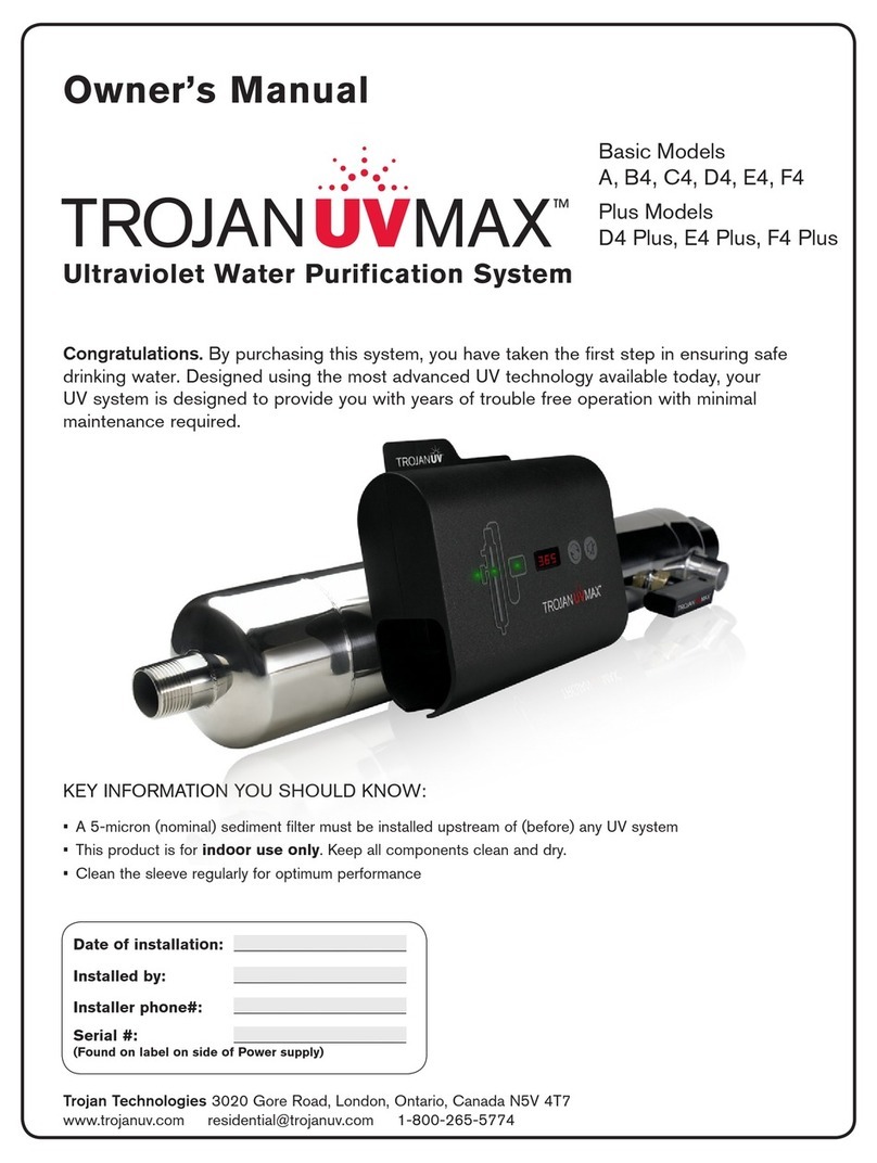
Trojan TrojanUVMax Pro10 User manual

Date of installation: ______________________
Installed by: ______________________
Installer phone#: ______________________
Serial #: ______________________
(Found on label on side of Power Supply)
A5-micron(nominal)sedimentfiltermustbeinstalledupstreamof
(before)anyUVsystem
Thisproductisforindooruseonly.Keepallcomponentscleananddry.
Cleanthequartzsleeveregularlyforoptimumperformance
•
•
•
KEYINFORMATIONYOUSHOULDKNOW:
Congratulations.Bypurchasingthissystem,youhave
takenthefirststepinensuringsafedrinkingwater.
DesignedusingthemostadvancedUVtechnology
availabletoday,yourUVsystemisdesignedtoprovide
youwithyearsoftroublefreeoperationwithminimal
maintenancerequired.
Trojan Technologies
3020GoreRoad,London,Ontario,CanadaN5V4T7
www.trojanuv.com[email protected]1-800-265-5774
Ultraviolet Water Purification System
Owner’s Manual
NSF information pertains to
TrojanUVMaxTM Pro Series models.
Systemtestedandcertified
byNSFInternational
againstNSF/ANSI
Standard55fordisinfection
performance,ClassA.
ProSeries(Pro10,Pro20&Pro30)
PlusSeries(G+,H+,J+)
BasicSeries(G,H,J)

WARNING–
Toguardagainstinjury,basicsafetyprecautionsshouldbeobserved,includingthefollowing:
READANDFOLLOWALLSAFETYINSTRUCTIONS.
DANGER–Toavoidpossibleelectricshock,specialcareshouldbetakensincewaterisemployedintheuseofthissystem.Unlessa
situationisencounteredthatisexplicitlyaddressedbytheprovidedmaintenanceandtroubleshootingsections,donotattemptrepairs
yourself;refertoanauthorizedservicefacility.
CAUTION-Donotoperatewithbrokenorfaultypartsasthismayresultinexposuretoultravioletradiation.Contactsupplierforreplacement
parts.
Donotoperatethesystemifithasadamagedcordorplug,orifitismalfunctioningorifithasbeendroppedordamagedinanymanner.
Alwaysunplugthesystem,shutoffwaterflowandreleasewaterpressurebeforeservicingorcleaning.Neveryankcordtoremovefrom
outlet;graspthewallplugandpulltodisconnect.
Donotusethesystemforotherthanintendeduse.Theuseofattachmentsnotrecommendedorsoldbythemanufacturermaycausean
unsafecondition.
Topreventriskofelectricalshock,connectthissystemonlytoaproperlygrounded,grounding-typepowersupplyreceptaclethatis
protectedbyaGroundFaultCircuitInterrupter(GFCI).InspectperformanceofGFCIaspermanufacturer’ssuggestedmaintenance
schedule.Ifanextensioncordisused,ensureitisofasufficientratingandacceptstheplugfromthissystem;neveruseanadapter.
Visuallyinspectthissystempriortoinstallation.Ifthequartzsleeveorlampisbroken,crackedordamagedinanyway,donotuse.Contact
thesupplierforreplacementparts.
Keepallconnectionsdryandofftheground.Donottouchplugwithwethands.
Thelightemittedbythelampwillcauseseriouseyedamageandburnunprotectedskin.Donotplugsystemintoanelectricaloutletwithout
firstproperlysecuringthelampintothechamber.Unplugthesystempriortoremovingthelampfromthechamber.
IftheUVsystemmalfunctionsorfails,watermustbeboiledpriortoconsumptionuntiltheUVsystemisoperationalandthewaterlineshave
beenshocked.Systemfailureisindicatedbythesystem’saudibleandvisualalarmsortheabsenceofanyindicatorlight.
Intendedforindooruseonly.Systemmustnotbeexposedtoweatherelements.Inseasonalapplications,chambermustbedrainedto
preventfreezing.
Installationofthissystemmustbeinaccordancewithlocalplumbingandelectricalcodesaswellasanyandallapplicableregulationsand
laws.
SAVETHESEINSTRUCTIONS.
Note:maximumpressureratingis100PSI(6.89bar)
1.
2.
3.
4.
5.
6.
7.
8.
9.
10.
11.
12.
13.
14.
SAFETY INSTRUCTIONS
GROUNDING
Thisproductmustbegrounded.Ifitshouldmalfunctionorbreakdown,groundingprovidesapathofleastresistanceforelectriccurrenttoreduce
theriskofelectricalshock.Thissystemisequippedwithacordhavinganequipment-groundingconductorandagroundingplug.Theplugmust
bepluggedintoanappropriateoutletthatisproperlyinstalledandgroundedinaccordancewithalllocalcodesandordinances.
DANGER–Improperconnectionoftheequipment-groundingconductorcanresultinariskofelectrocution.Checkwithaqualifiedelectrician
orservicepersonnelifyouareindoubtastowhethertheoutletisproperlygrounded.Donotmodifytheplugprovidedwiththissystem–ifitwill
notfittheoutlet,haveaproperoutletinstalledbyaqualifiedelectrician.Donotuseanytypeofadapterwiththissystem.
GROUND FAULT CIRCUIT INTERRUPTER PROTECTION
TocomplywiththeNationalElectricalCode(NFPA70)andtoprovideadditionalprotectionfromtheriskofelectricshock,thissystemshould
onlybeconnectedtoaproperlygrounded,grounding-typepowersupplyreceptaclethatisprotectedbyaGroundFaultCircuitInterrupter
(GFCI).InspectoperationofGFCIaspermanufacturerssuggestedmaintenanceschedule.
EXTENSION CORDS
Ifanextensioncordisnecessary,useonly3-wireextensioncordsthathave3-pronggrounding-typeplugsand3-polecordconnectorsthat
accepttheplugfromthissystem.Useonlyextensioncordsthatareintendedforoutdooruse.Useonlyextensioncordshavinganelectrical
ratingnotlessthantheratingofthesystem.Acordratedforlessamperesorwattsthanthissystemratingmayoverheat.Exercisecautionwhen
arrangingthecordsothatitwillnotbetrippedoverorpulled.Donotusedamagedextensioncords.Examineextensioncordbeforeusingand
replaceifdamaged.Donotabuseextensioncord.Keepextensioncordawayfromheatandsharpedges.Alwaysdisconnecttheextensioncord
fromthereceptaclebeforedisconnectingthissystemfromtheextensioncord.Neveryankcordtopullplugfromoutlet.Alwaysgrasptheplug
andpulltodisconnect.
WARNING–Topreventriskofelectricalshock,connectthissystemonlytoaproperlygrounded,grounding-
typepowersupplyreceptaclethatisprotectedbyaGroundFaultCircuitInterrupter.Pullplugbefore
servicingorreplacinglamp.Keepallconnectionsdryandofftheground.Donottouchplugwithwethands.
WARNING–Readmanualbeforeinstallingorservicingthissystem.Onlyauthorizedpersonnelpossessinga
strongunderstandingofthissystemshouldattempttoreplacelamporservicethissystem.
WARNING–DonotlookdirectlyatUVlampwhenitisoperating.Thelightemittedbythelampwillcause
seriouseyedamageandburnunprotectedskin.
NOTE–Maximumpressureratingis100PSI(6.89bar)

INSTALLATION WARRANTYMAINTENANCEOPERATION
OVERVIEW
TABLE OF CONTENTS
Overview 4
Components 4
Specifications 5
Dimensionsandlayout 7
Installation 9
InstallingtheUVsystem 9
Disinfectingthewaterlines 11
Operation 14
Controlpanel 14
Troubleshooting 15
LowUValarms 16
Maintenance 17
Sleevecleaningandlampreplacement 17
Fusereplacement 22
Warranty 23

INSTALLATIONWARRANTY MAINTENANCE OPERATION OVERVIEW
Power supply
Pro10:part#650629-010G+:part#650629-070G:part#650629-040
Pro20:part#650629-020H+:part#650629-080H:part#650629-050
Pro30:part#650629-030J+:part#650629-090J:part#650629-060
(includeslampcable)
Top bolt & wireform
Part#602916&602896
Sleeve
Pro10,G+,G:part#602974
Pro20,H+,H:part#602975
Pro30,J+,J:part#602976
O-ring
Part#002233
CoolTouchTM fan
Part#650630
Sensor
(ProandPlusSeriesonly)
Part#650580
O-ring
Part#002233
Bottom bolt
Part#602984
Lamp
Pro10,G+,G:part#602854
Pro20,H+,H:part#602855
Pro30,J+,J:part#602856
Chamber
Pro10,G+,G:part#650565-003
Pro20,H+,H:part#650565-007
Pro30,J+,J:part#650565-011
Power cord
120V:part#602636
230V:part#602637
For replacement components please contact your
installer (listed on the front of this manual) or contact
Trojan directly for a referral: 1-800-265-5774 (North
America), 519-457-3400, or [email protected].
Sleeve removal tool
Part#602983
Note: keep this tool with
system at all times.
Lamp cable
Part#650631-048
Accessory Part Number
1"SolenoidValve 650627
COMMcentre
RemoteController
(ProSeriesonly)
650623-001
Plug Kit
(ComesinstalledwithBasic
Serieschamber)
COMPONENTS
4

INSTALLATION WARRANTYMAINTENANCEOPERATION
OVERVIEW
SPECIFICATIONS
Operating Parameters
Maximumoperatingpressure 100PSI(689kPa)
Minimumoperatingpressure 10PSI(69kPa)
Maximumambientairtemperature 1040F(400C)
Minimumambientairtemperature 320F(00C)
Maximumhumidity 100%
Maximumhardness 120ppm
(7grainspergallon)
Maximumiron 0.3ppm
MinimumUVT 75%
Installation Vertical
Other
Chambermaterial 316LSST
Ratedservicelifeoflamp 2years
Inletandoutlet Combo
11/4"NPT,1"FNPT
General (All Models)
Ratedflow
doseof
30mJ/cm2-- -- --
upto19GPM*
(72LPM)
20-39GPM*
(76-148LPM)
40-45GPM*
(151-170LPM)
Ratedflow
doseof
40mJ/cm2
10GPM
(38LPM)
20GPM
(76LPM)
30GPM
(114LPM)
upto15GPM*
(57LMP)
16-29GPM*
(61-110LPM)
30-44GPM*
(114-167LPM)
Electrical
Voltage 120-240VAC 120-240VAC 120-240VAC 120-240VAC 120-240VAC 120-240VAC
Frequency 50-60Hz 50-60Hz 50-60Hz 50-60Hz 50-60Hz 50-60Hz
Max.current 1.2Amp 1.6Amp 2.4Amp 1.2Amp 1.6Amp 2.4Amp
Max.power
consumption
120Watts 160Watts 230Watts 120Watts 160Watts 230Watts
Lamppower
consumption
100Watts 140Watts 200Watts 100Watts 140Watts 200Watts
Pro10 Pro20 Pro30 G+, G H+, H J+, J
*Flowratesshownareat85%UVT.
5

INSTALLATIONWARRANTY MAINTENANCE OPERATION OVERVIEW
SPECIFICATIONS
Color-codedplugandplayconnections Yes Yes Yes
UVintensitymonitorwithdiagnostictest Yes Yes --
CoolTouchfan Yes Yes Yes
Dynamicflowrestrictor Yes -- --
Communicationsports(two,RJ45) Yes Yes Yes
COMMcentercontrolpackage Optional -- --
Solenoidvalve Optional Optional Optional
Controls
Audiblealarmmutebutton Yes Yes Yes
Newlampbutton Yes Yes Yes
Lampageindicator Yes Yes Yes
Lampoperationindicator Yes Yes Yes
Ballastoperationindicator Yes Yes Yes
Solenoidoperationindicator Yes Yes Yes
Fanoperationindicator Yes Yes Yes
Sensorreadingindicator Yes Yes --
NSF/ANSI certification
(ProSeriesonly)
Standard55
ClassA
-- --
Other certifications
Pro Series Plus Series Basic Series
6

Seenextpagefordescriptionsofnumberedparts
Inlet
6
1 2
3
54
13
12
b
L
a
Ø
e
d
S
1011
7
8
9
c
Clearancefor
lampremoval(L)
14
INSTALLATIONWARRANTY MAINTENANCE OPERATION
INSTALLATION WARRANTYMAINTENANCEOPERATION
OVERVIEW
DIMENSIONS & LAYOUT
LModel
Pro10,G+,G 21.4"
(55cm)
12"
(30cm)
4"
(10cm)
48"
(122cm)
72"
(182cm)
72"
(182cm)
6.5"
(16.5cm)
13"
(33cm)
Pro20,H+,H 30.8"
(78cm)
12"
(30cm)
4"
(10cm)
48"
(122cm)
72"
(182cm)
72"
(182cm)
6.5"
(16.5cm)
13"
(33cm)
Pro30,J+,J 40.6"
(103cm)
12"
(30cm)
4"
(10cm)
48"
(122cm)
72"
(182cm)
72"
(182cm)
6.5"
(16.5cm)
13"
(33cm)
Øedc
(max.)
b
(max.)
a
(max.)
S
(min.)
7

WARRANTYMAINTENANCEOPERATION
INSTALLATIONWARRANTY MAINTENANCE OPERATION OVERVIEW
Sample valve: Allowsforsamplingofrawwater.
Shut-off valve: Requiredtoallowmaintenanceofpre-treatmentequipment.
Pre-treatment (illustrative only):FortheUVsystemtooperateeffectively,thewatershouldmeetcertain
waterqualityparameters,asoutlinedbelow.Tomeetthese,pre-treatmentofthewatermayberequired.
Pre-treatmentequipmentmustbeinstalledBEFOREtheUVchamber.Pre-treatmentsystemscanbe
comprisedofoneormoreofthefollowingelements:sedimentfilters;carbonfilters;ironremovalsystems;
watersofteners;cystreductionfilters,etc.
Water Quality Requirements:
Iron: <.3PPM(.3mg/L)
Hardness: <120PPM(7GrainsPerGallon)
%UVT: >75%
1
2
3
4
5
Shut-off valve: RequiredtoallowmaintenanceofUVsystem.
Sample valve:AllowsforsamplingofwaterenteringUVchamber;necessaryinordertoconfirmwater
beingtreatedisofadequatequality.
UV chamber:Providesdisinfectionofthewater.MUSTBEINSTALLEDVERTICALLY.
Sensor:OptionalitemthatmonitorsUVoutputtoensureproperdose(UVexposure)isbeingprovided.
Uniquetestfunctionallowsverificationofsensoroperation.
Plug Kit: Astopperforthechamberopeningcreatedforasensorwhennosensorisinuse.
CoolTouchTM fan:Removesexcessheatfromstagnantwaterinchamberduringperiodswithoutwaterflow.
Sample valve:AllowsforverificationofsamplingofwaterimmediatelyfollowingUVtreatment;necessaryin
ordertoconfirmproperoperationofUVsystem.
Solenoid valve:OptionalpieceofequipmentsuppliedbyTrojan.Allowswatersupplytobeshut-offwhen
properdisinfectioncannotbeassured.Manualby-passallowsfordisinfectionofwaterlinesusingchlorine
bleach,followinginstallationandmaintenanceprocedures.
Note:Ifthegroundfromtheelectricalpanelistiedtothecopperwaterlines,theuseofasolenoidvalvewillrequire
theinstallationofanapprovedgroundstraptoconnectthetwolinesthathavebeencutinordertomaintaincontinuity.
Checkyourlocalelectricalcodeforthecorrectclampandcablesize.
Shut-off valve: RequiredtoallowmaintenanceofUVsystem.
Power supply:PowersandcontrolstheUVlampandotherdevices.Provideshumaninterface,displaying
informationandallowingcontrolinputs(suchasmutingtheaudiblealarm).
Power source:Providespowertothepowersupply.Forsafetyreasonstheoutletmustbeprotectedby
aGroundFaultCircuitInterrupter(GFCI).NOTE:toprotectthepowersupply,aUL1449certified(or
equivalent)transientvoltagesurgesuppressorisrecommended.
6
7
8
9
10
11
13
12
14
IMPORTANT:
A 5 micron (nominal) sediment filter must be installed
before the UV system and after any water softening equipment
8

INSTALLATION
OVERVIEW WARRANTYMAINTENANCEOPERATION
INSTALLING THE UV SYSTEM
Determineappropriatelocationofthe
powersupplyandchamber,referringto
Dimensions and Layoutdrawing.Power
supplyshouldbeinstalledhigherthan
chamber.Ensureadequateclearance
abovechambertoallowforremovalofthe
lampandsleeve.
Makeallnecessaryplumbingconnections.
Attachchamber
towallvertically.
4
1
3
2
10
WetO-ring
withwater
thenplace
overtopend
ofsleeve.
5
6
7
8
9
Donottouch
glasswith
barehands.
Insertcurved
endofsleeve
first.Donot
rotatesleeve.
Ensure
sleevebolt
isrotatedfull
1/4turnuntil
positivestop.
Ensure
sleevebolt
isrotatedfull
1/4turnuntil
positivestop.
WetO-ringwith
waterthenplace
overbottomend
ofsleeve.
Only
forPro
andPlus
Series.
1
2
1
2
1
2
9

INSTALLATION
OVERVIEWWARRANTY MAINTENANCE OPERATION
PlugCoolTouchfanintopurplereceptacle.
19
18
20
12
13
14
17
15
1611
Outletmustbe
protectedbya
GroundFault
CircuitInterrupter
(GFCI).
41/16"(10.4cm)
1
2
1
2
Do not touch
glass with
bare hands.
Be sure to
rotate lamp
completely.
Letwaterflowtoonefaucetorotherwater
outlet,thenclosetheoutletandcheckfor
leaks.
ProceedtoDisinfecting The Water Lines.
Lock wireform
into position.
Plugsensor
intobluejack.
(ForProand
PlusSeries
only).
10

INSTALLATION
OVERVIEW WARRANTYMAINTENANCEOPERATION
DISINFECTING THE WATER LINES
UVsystemsdisinfectthewaterusingultravioletlight,treatingthewaterasitpassesthroughthesystem.When
thereisariskthatwaterdownstreamoftheUVsystemhasbeencontaminateditiscriticalthatthesewaterlines
bechemicallydisinfected.Disinfectionofthewaterlinesisthereforerequiredafterinitialsysteminstallationand
followinganyextendedperiodoftimeduringwhichthesystemisinoperative,whetherduetoanalarmcondition,
apowerfailure,orforanyotherreason.
1
3Turn on solenoid valve override
(if so equipped).
4
5
6
7
8
2
11

OVERVIEWWARRANTY MAINTENANCE OPERATION
INSTALLATION
16
Gotoawateroutletandallowthecold
watertoflowuntilyoucansmellbleach,
thenstoptheflow.Allowhotwater(if
present)toflowuntilyoucansmellbleach,
thenstoptheflow.Repeatprocedureat
allwateroutlets.Remembertoincludeall
faucets,washingmachines,toilets,outside
taps,andotherwateroutlets.Note:Youwill
likelyrunoutofbleach;ifyoucannotsmell
bleachatagivenoutlet,turnoffthemain
watersupply,depressurizeandaddmore
bleachtothefilterhousing.
Letthebleachsitinthewaterlinesforat
leastfourhours.
9
11
10
12
13
14
15
12

INSTALLATION
OVERVIEW WARRANTYMAINTENANCEOPERATION
19
20
Flush all water outlets until bleach can no
longer be smelled (at least 5 minutes).
Turn off solenoid valve override (if
so equipped).
17
18
13

INSTALLATION OVERVIEWWARRANTY MAINTENANCE OPERATION
Indicator lights
Operatingnormally Notapplicable Powersupplyfailure;replacepower
supply
Ballastinactiveduetolampfailure
Operatingnormally Notapplicable Fandisconnected;reconnect
Fanturningslowerthanrequired;
unplugsystem,cleanbladesusing
aQ-tip
Fandamaged;replacefan
Notapplicable
Operatingnormally Warning;lamp
willrequire
replacementshortly
Lampdisconnected;unplugsystem,
reconnectlampandplug-insystem
again
Lampfailure;replacelamp
Lampinactiveduetoballastfailure
UVdoseisadequate
andsensorisoperating
normally
(Pro&Plusmodelsonly)
UVdoseisnearthe
minimumrequired
Sensordisconnected;unplugsystem,
reconnectsensorandplug-insystem
again
UVdoseisbelowminimumrequired,
seeLow UV Alarm section
Sensorinactiveduetolampor
ballastfailure
Solenoidvalveopen
(Ifequippedwith
solenoid)
Notapplicable Solenoidvalvedisconnected;
reconnect
Solenoidcoildamaged;replacecoil
(notentiresolenoid)
Solenoidvalveinactive(closed)
duetofailureofanother
component,inordertoensure
safetyofthewatersupply
Yellow Flashing red Solid redGreen
4
1
3
2
5
Indicator lights only indicate a problem with the component when flashing red.
CONTROL PANEL
4
1
3
5
2
Buttons
Mute Pressthisbuttoninorder
toturnofftheaudible
alarm.Whenthealarmis
duetothelamp'sage,the
mutebuttonwilldeactivate
theaudiblealarmfor7
days;thismayberepeated
uptoamaximumof4
times.
NewLamp Afterinstallinganew
lamp,pressandholdthis
buttonuntilyouheara
beep(aboutfiveseconds).
Thiswillresettheinternal
clock.
Meaning
A
B
Button
A
B
14

INSTALLATION WARRANTYMAINTENANCE
OPERATION
OVERVIEW
TROUBLESHOOTING
Nopower GFCIand/orbreakertripped
Powersupplyfusehasblown
Transientvoltagesurgesuppressor
damaged
Powersupplydamaged
ResetGFCIand/orbreaker
Replacepowersupplyfuse-seeFuse
Replacementsection
Replacetransientvoltagesurge
suppressor(TVSS)
ReplacepowersupplyanduseaTVSS
GFCIorbreaker
repeatedlytrips
Connectionbetweenlampandlampcord
iswet
Short-circuitintheelectricalassembly
Cleananddrythecordandendlamp
pins,checkunitforleaksorcondensation
Replacepowersupply
Leakatinletor
outlet
Threadedpipefittingsareleaking Cleanthreads,resealwithTeflontape
andretighten
Leakdetectedfrom
areaofchamber
Condensationofmoistaironcold
chamber(slowaccumulation)
O-ringdamaged,deterioratedor
incorrectlyinstalled
Sleeveboltnottightenough
Controlhumidityorrelocateunit
Inspectandreplaceifdeteriorated
Ensurenutisturnedcompletely(tostops)
Alarm SeeControl Panelsection SeeControl Panelsection
Systemisoperating
butwatertests
revealbacterial
contamination
EquipmentdownstreamofUVsystem
isactingasabreedinggroundfor
pathogens
Pathogensareresidinginthedistribution
linespost-UV
Recontaminationfrompipedead-ends
EnsureUVisthelastpieceoftreatment
equipment
Ensurealldistributionlineshave
beendisinfectedwithchlorine-see
Disinfecting the Water Linessection
Removeanypipedead-endsandflush
withchlorine-seeDisinfecting the
Water Linessection
Possible cause Possible solutionSymptom
15

INSTALLATION OVERVIEWWARRANTY MAINTENANCE OPERATION
Insomecases,short-termflowsoflowultraviolettransmittance(UVT)watercanbecreatedfollowing
andduringtheregenerationcycleofawatersoftener,resultinginasensoralarm.FlushingtheUVsystem
alleviatesthisconditionuntilthesoftenergoesthroughanotherregenerationcycle.Inthelongerterm,the
softener'ssettingsmustbemodified.ToflushtheUVsystem,firstturnthesolenoidvalvebypassswitch(if
equipped)counter-clockwisetooverridetheshut-off,thenopenatapdownstreamandletwaterrunfor
two(2)minutes.Disinfectthewaterlinesfollowingtheproceduresoutlinedunder"Disinfecting The Water
Lines"intheInstallationsection.
ProandPlusSeriesareequippedwithaunique,patentedsensorthatiscapableofself-diagnosis.Simply
pressthebuttonlocatedatthetopofthesensorandholduntiltheaudiblealarmstops(usuallyabout5
seconds).Iftheaudiblealarmisstillpresentafter30seconds,releasethebuttonandreplacethesensor.
RefertoSleeve Cleaning And Lamp ReplacementsectionoftheOwner'sManual.
ContactTrojanoryourwatertreatmentdealerforatestoftheUVTofthewater.
1�
2�
3�
4�
LOW UV ALARMS (Pro & Plus Series Only)
Sensortest2
Low UV Alarm
Cleansleeve&sensor3
Audible alarm
Audible alarm
Problem is
corrected
No audible alarm
No audible alarm
CheckUVT4
ContactTrojan
UVT above 75%
UVT below
recommended
level
Replacesensor
IncreaseUVTusing
pretreatment
Sensoris
operating
normally
Flushsystem1
Audible alarm
Problem is
corrected
No audible alarm
16

INSTALLATION
OVERVIEW WARRANTY
MAINTENANCE
OPERATION
Sleeve cleaning
Mineralsinthewaterslowlyformacoatingonthesleeve.Thiscoatingmustberemovedbecauseitreducesthe
amountofUVlightreachingthewater,therebyreducingdisinfectionperformance.Theneedtocleanthesleeve
willbeindicatedbyalowUValarm(flashingredindicatorlightbesidethesensoroncontrolpanel-seeControl
Panelsectionfordetails).
Note:LowUValarmsareforPro&PlusSeriesonly.IfyouownaBasicmodel,pleasecleanthesleeveregulary
(agoodruleofthumbis3-4timesperyear).
Whencleaningisrequired,followtheinstructionsbelowandre-installthecurrentlamp.
Lamp replacement
TheamountofUVlightcreatedbythelampdecreasesovertime,requiringthatthelampbereplaced.The
systemwillautomaticallynotifyyouwhenitistimetoreplacethelamp(thelampshouldlastapproximately24
months).Ifthelamprequiresreplacement,followtheinstructionsbelowandinstallanewlamp.NOTE:TheUV
systemisdesignedtooperatecontinuouslyandshouldnotbeshutoffforshortperiodsoftime,suchasovera
periodoflessthanthreeweeks.
Equipment required:
SLEEVE CLEANING & LAMP REPLACEMENT
Cloth must be
soft, lint-free, and
chemical-free. No
clean-wipes.
Scale remover
such as CLRTM or
Lime-AwayTM.
Screwdirver of any
kind.
Cottom swab. Clean cotton, latex
or plastic gloves
are prefered.
17

INSTALLATION OVERVIEWWARRANTY MAINTENANCE OPERATION
4Letthesystemcoolfor10minutes.
3
2
6
5
1Solenoidrepresentativeonly.Notonall
systems.
Solenoid
10
7
Close
after all
water has
drained.
8
9Pinch
wireform to
release it.
18

INSTALLATION
OVERVIEW WARRANTY
MAINTENANCE
OPERATION
19 Ensure cloth used to clean the sleeve is
soft, lint-free, and contains no chemicals
(no clean-wipes). Sleevemustbereplaced
ifitcannotbecompletelycleanedorifit
appearsscratchedorcracked.
13
1
2
1
12
2
1
11 Do not touch
glass with bare
hands.
2
16 Remove sleeve.
Water will
escape - have
bucket under
chamber.
14
Sleeve removal tool
Insert sleeve
removal tool
into bottom
of sleeve
15
Pry sleeve
upward until it
comes loose.
Some water
will escape.
18
Remove O-ring
from bottom of
chamber.
Remove
O-ring
from top
of sleeve.
17
1
1
19

INSTALLATION OVERVIEWWARRANTY MAINTENANCE OPERATION
27 Re-install
current lamp if
it does not need
replacement. Be
sure to rotate
lamp completely.
Do not touch
glass with bare
hands.
1
2
24
1
2
20
1
2
Ensure
sleeveboltis
fullyrotated
untilpositive
stop.
23
1
2
Ensure
sleeveboltis
fullyrotated
untilpositive
stop.
26
1
2
Ensure
sleeveboltis
fullyrotated
untilpositive
stop.
21 Donottouch
glasswith
barehands.
Insertcurved
endofsleeve
first.Donot
rotatesleeve.
25
WetO-ringwith
waterthenplace
overbottomend
ofsleeve.
29
22 WetO-ring
withwater
thenplace
overtopend
ofsleeve.
28 ForBasicSeries,skipto
Step31.
20
This manual suits for next models
8
Table of contents
Other Trojan Water Filtration System manuals
Popular Water Filtration System manuals by other brands

HEISSNER
HEISSNER FPU24000-00 Instructions for use

Pentair Pool Products
Pentair Pool Products Meteor Series owner's manual

Culligan
Culligan WH-S100-O Installation and operation instructions

Allied Pumps
Allied Pumps KCPS 15FS Installation, operation and maintenance manual

Vulcan-Hart
Vulcan-Hart SCALEBLOCKER SPS600V Installation & operation manual

Emerson
Emerson NL4-FLC Series RE-ASSEMBLY INSTRUCTIONS