Trolex RockMonitor XM Telltale TX5021 User manual


RMXM Telltale User Manual
www.trolex.co
m
P5625.1607 Rev A 2
TX5021 Telltale
Contents
General Description............................................................................................................................................................................................................. 3
Main features .................................................................................................................................................................................................................4
Theory of operation......................................................................................................................................................................................................4
RockMonitor XM Telltale –TX5021 ........................................................................................................................................................................6
Certification and Approvals ............................................................................................................................................................................................. 7
Mechanical non-electrical equipment ....................................................................................................................................................................7
Technical Information ........................................................................................................................................................................................................ 8
Product Specifications ................................................................................................................................................................................................8
Product Dimensions.....................................................................................................................................................................................................9
Hardware Installation ...................................................................................................................................................................................................... 10
Telltale Installation .....................................................................................................................................................................................................10
Telltale Orientation.....................................................................................................................................................................................................14
General Operation .............................................................................................................................................................................................................16
Measuring Displacement..........................................................................................................................................................................................16
Extending the Measurement Range...................................................................................................................................................................... 17
Maintenance .......................................................................................................................................................................................................................18
Visual Checks...............................................................................................................................................................................................................18
Cleaning Labels ...........................................................................................................................................................................................................18
Check Mechanism for Seizure or Jamming ........................................................................................................................................................18
Replacing Telltales .....................................................................................................................................................................................................18
System Troubleshooting and Diagnosis ......................................................................................................................................................................19
Reset Handle................................................................................................................................................................................................................19
Technical Support
..........................................................................................................................................................................................................19
Disclaimers
......................................................................................................................................................................................................................20
Revisions ...........................................................................................................................................................................................................................20
Feedback ............................................................................................................................................................................................................................21
Trademarks........................................................................................................................................................................................................................21
www.trolex.com
3 P5625.1607 Rev A
General Description
The Trolex RockMonitor XM is a mechanical extensometer designed to monitor the condition of roof-
bolted underground roadway or cut-through strata. It offers a fully mechanical solution for measuring
displacement of tunnel strata, allowing geotechnical engineers and mine operators to periodically
monitor and assess critical information regarding the safety and effectiveness of roadway support
structures.
Mechanical extensometers (hereafter referred to as telltales) give local visual indication of
displacement measurement to provide information regarding strata condition. Spring anchors are
used to locate a set of wires at different heights inside a borehole. The wires are connected to the
visual indicator measurement mechanism. Any dilation or bed separation of the strata will appear to
pull the indicators along their axis showing how much each anchor has moved (relative to roadway
roof).
Telltales can be installed at varying intervals in the sides as well as the roof of a tunnel and are
designed for ease of installation, measurement accuracy and mechanical re-set as required (up to
150mm of measurement displacement without re-set).
RockMonitor XM Telltale

RMXM Telltale User Manual
www.trolex.co
m
P5625.1607 Rev A 4
Main features
•
Continuous monitoring of strata displacement
•
Strata displacement measurement up to 150mm (without reset)
•
Resettable height measurement for movement in excess of 150mm
•
Two or four monitoring points (anchor heights) between 0.6m and 16m
•
Highly visible display of displacement measurement on-device
•
Simple and robust installation methodology
Theory of operation
The RockMonitor XM Telltales can be configured with either two or four measurement heights.
Anchor wires are inserted into a borehole drilled either in the roof or sidewall of a roadway and
secured into position using spring anchors connected to the ends of the wires. The tube section of
the telltale is then inserted into the borehole with securing features automatically gripping the sides
of the borehole and keeping the telltale in position in the tunnel roof or side wall. Any displacement
of the strata occurring within the height of the anchors will cause the body of the RockMonitor XM
Telltale to move relative to the anchor. The anchor wires connect the anchor points to mechanical
measurement units housed within the body of the telltale. Movements are then shown visually on-
device and can be recorded at determined manual reading intervals.
The use of multiple anchor points allows more detailed insight into where the strata displacement is
occurring. A typical installation would use a minimum of two anchors, placing one above the bolted
height and one within the bolted height. This can provide valuable insight into the effectiveness of
the chosen support strategy. The four-anchor version provides even more data with which to
optimise bolting strategies or support strata investigations.

www.trolex.com
5 P5625.1607 Rev A
Installation position. No
strata movement indicated –
all displacement markers
read 0mm on the
measurement scale.
Displacement occurs
between anchor 1 and 2 as
shown by ‘X’. Anchor 1
displacement marker
moves to indicate the
amount of displacement.
Second displacement
occurs between anchors 3
and 4 as shown by ‘Y’.
Anchor 2 and 3
displacement markers
move to represent
displacement figure ‘Y’,
whilst anchor 1
displacement marker
moves to represent a total
distance of ‘X + Y’.
Displacement measurement
0
X
X + Y
(Total)
Y
X
Y
A.
B.
C.
Anchor 1
(Total)
Anchor 2
Anchor 3
Anchor 4
(Lower)
Anchor 1
(Total)
Anchor 2
Anchor 3
Anchor 4
(Lower)
Anchor 1
(Total)
Anchor 2
Anchor 3
Anchor 4
(Lower)
Strata Displacement
X
Strata Displacement
Y
Displacement marker movement

RMXM Telltale User Manual
www.trolex.co
m
P5625.1607 Rev A 6
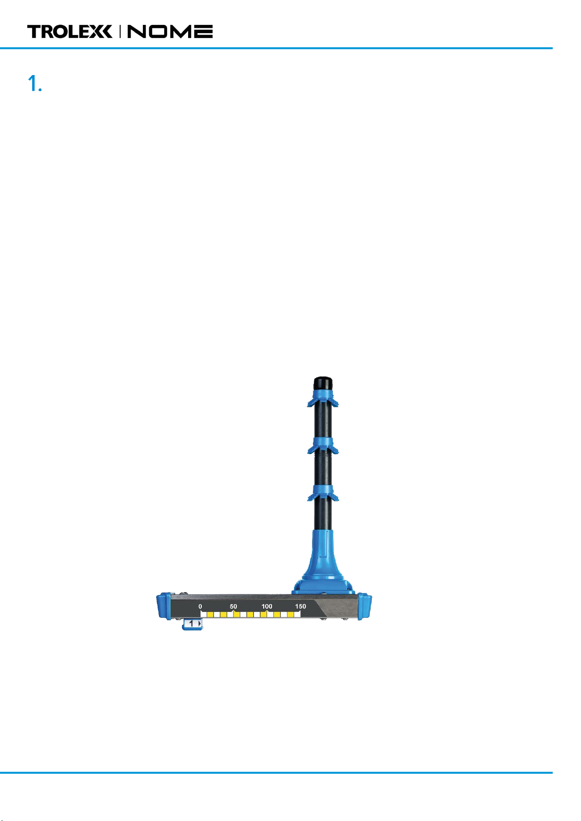
RockMonitor XM Telltale –TX5021
The mechanical measurement system is housed within a robust stainless-steel enclosure that
remains visible after installation in the tunnel roof. Anchor springs fix the anchor wires into the
borehole at the required measurement depths (within or above the bolted height) whilst the vertical
tube is secured into the borehole by the three borehole grippers. This allows the stainless-steel body
of the device to maintain a low profile to the roof or side wall.
As displacement occurs, the anchor wires pull a mechanical assembly through the instrument body
to measure strata displacement. The anchor wires are secured to the measurement mechanism using
clamping devices with a spring providing tension on the wires to ensure accurate measurement.
Measurement indicators give easily visible local information regarding displacement of each
individual anchor.
The figure below shows an individual telltale with four anchors (note that the full lengths of the
anchor wires are not shown).
Spring retention
anchors
2 or 4
measurement
height anchors
Water diverting
features to prevent
ingress
Installation
hook
Borehole mounting
anchors
Borehole mounting
bracket
Highly visible measurement
scale to aid reading from a
distance
Installation wire reels up to 15m
Nylon coated wire to
prevent corrosion
Displacement marker
installation tab
Displacement markers with pull
handle for installation and
reset
Certification details
Detailed measurement markers
for in-situ displacement readings

www.trolex.com
7 P5625.1607 Rev A
Certification and Approvals
Mechanical non-electrical equipment
The RockMonitor XM Mechanical Telltale is a mechanical, non-electrical equipment that is operated
and installed under human power only. The instrument has no potential ignition hazards which are
not solely due to the materials of construction. The RockMonitor XM Mechanical Telltale is therefore
outside the scope of the ATEX Directive and does not require IECEx certification for use in Hazardous
Locations.
To minimise the risk of electrostatic discharge which may occur as a function of the use of the
equipment, please follow the guidance provided in IEC TS 60079-32-1 and any additional local
regulations.
Additional information for the risk assessment associated with the materials of construction:
1. Materials used in the construction of the Telltale (internal and external) do not contain, by mass:
•more than 15% in total of aluminium, magnesium, titanium and zirconium, and
•more than 6 % in total of magnesium, titanium and zirconium
2. Exposed external parts of the Telltale are not painted or coated with preparations containing, in
metallic form: aluminium, magnesium, titanium or zirconium.
3. The projected surface area of any external non-metallic part of the enclosure is less than 10 000
mm2.

RMXM Telltale User Manual
www.trolex.co
m
P5625.1607 Rev A 8
Technical Information
Product Specifications
TX5021 RockMonitor XM Telltale
Ambient temperature:
0 °C to +50 °C
Storage temperature:
-20 °C to +50 °C
Humidity:
10 to 98%
Protection classification:
Dust and waterproof to IP54
Housing materials:
SS316, PC/ABS
Net weight:
2.1kg
Measurement points:
2 or 4
Borehole diameter:
35 to 45 mm
Measurement range:
0 to 150 mm (without reset)
Accuracy:
<1.0mm
Repeatability:
<0.1mm

RMXM Telltale User Manual
www.trolex.co
m
P5625.1607 Rev A 10
Hardware Installation
The installation of the product must only be carried out by competent personnel. Each installation
needs to be considered with reference to the local safety regulations and authorities. Refer to the
following standards for additional guidance:
•
IEC/EN 60079-14
•
IEC/EN 60079-25
Refer to the Certification Section of this User Manual and to the relevant certificates for any
installation parameters and special conditions of safe use.
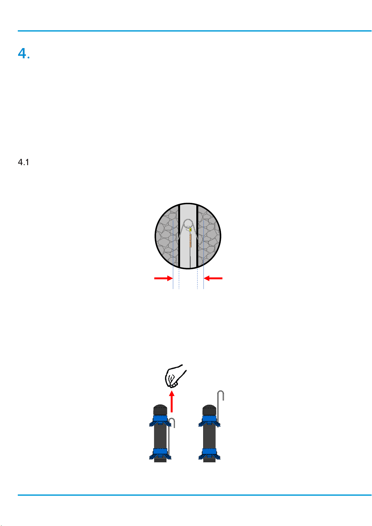
Telltale Installation
To install a RockMonitor XR Telltale into a tunnel roof or sidewall, follow the procedure below:
1.
Drill a 35mm-45mm borehole to the height required for the topmost anchor.
2.
Cut a hole in the roof mesh large enough to ensure there is no interference to the telltale body
once installed.
3.
Using the integrated installation hook located in the top anchor, hang the device off the roof
mesh as close to the bore hole opening as possible. Ensure the yellow installation hold-off tab
is left in place.

RMXM Telltale User Manual
www.trolex.co
m
P5625.1607 Rev A 12
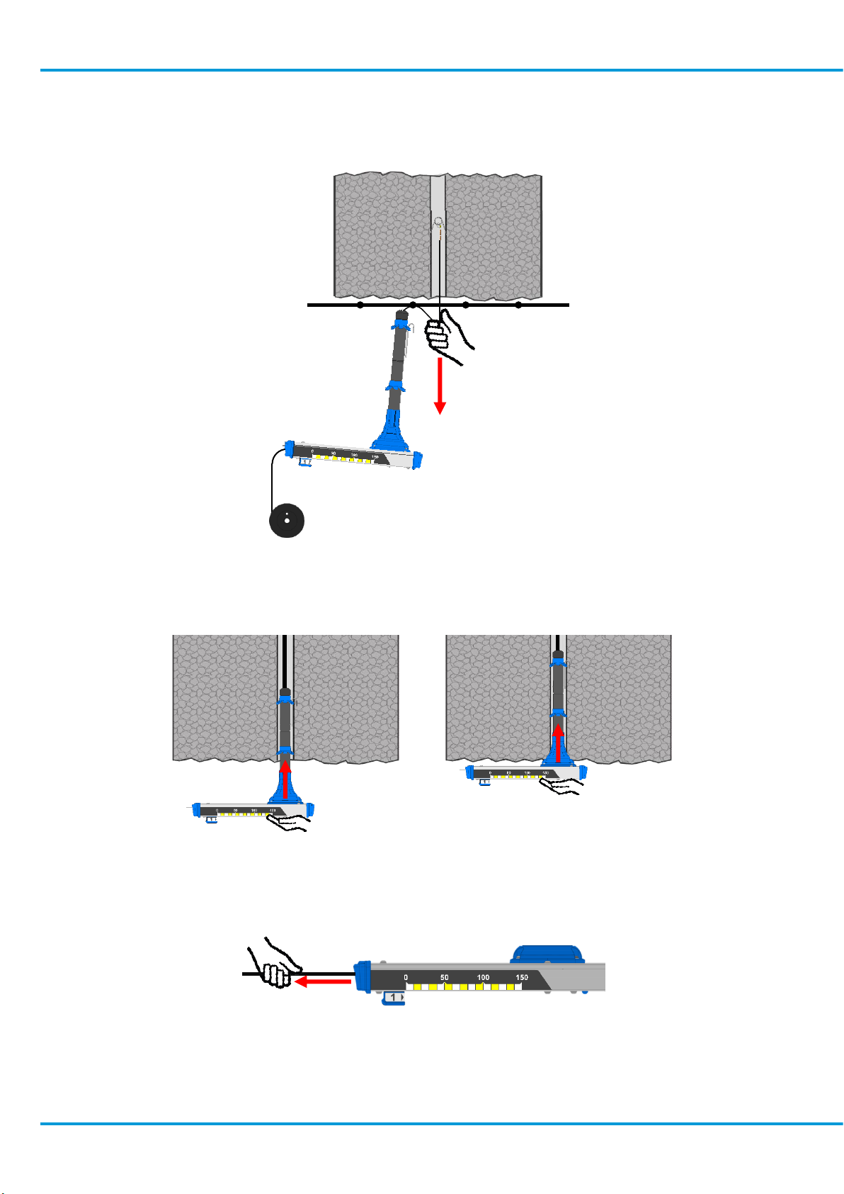
6.
Pull down on each wire placed into the bore hole to ensure the spring anchors find a lie within
the hole.
7.
Unhook the device from the mesh and push the device as far as it will go into the borehole
taking care to push from the center of the device body.
8.
Pull the slack cable through the device from the back end as you do this.
9.
Device orientation will be dependent on local strata conditions and should be determined on a
case by case basis. However, use of the side scale for viewing at distance requires the telltale
to be mounted perpendicular to the direction of travel.

www.trolex.com
13 P5625.1607 Rev A
10.
Remove the handle installation hold-off tab (the yellow plastic strip).
11.
Ensure all marker handles sit flush against the device and are not stuck in the down position.
12.
Pull on each cable coming out of the device to remove slack in the line.
13.
Excess cable can be removed with wire cutters. However, care must be taken to ensure there
is enough cable to allow for potential resetting of anchors.
14.
It is recommended that a suitable amount of cable remains after cutting to allow for any
number of anchor height resets. Each reset requires 150mm of cable, plus 100m of remaining
cable to allow for tensioning and to prevent the end of the cable being lost inside the device.
Please calculate the cable trim length based on your system requirements.

RMXM Telltale User Manual
www.trolex.co
m
P5625.1607 Rev A 14
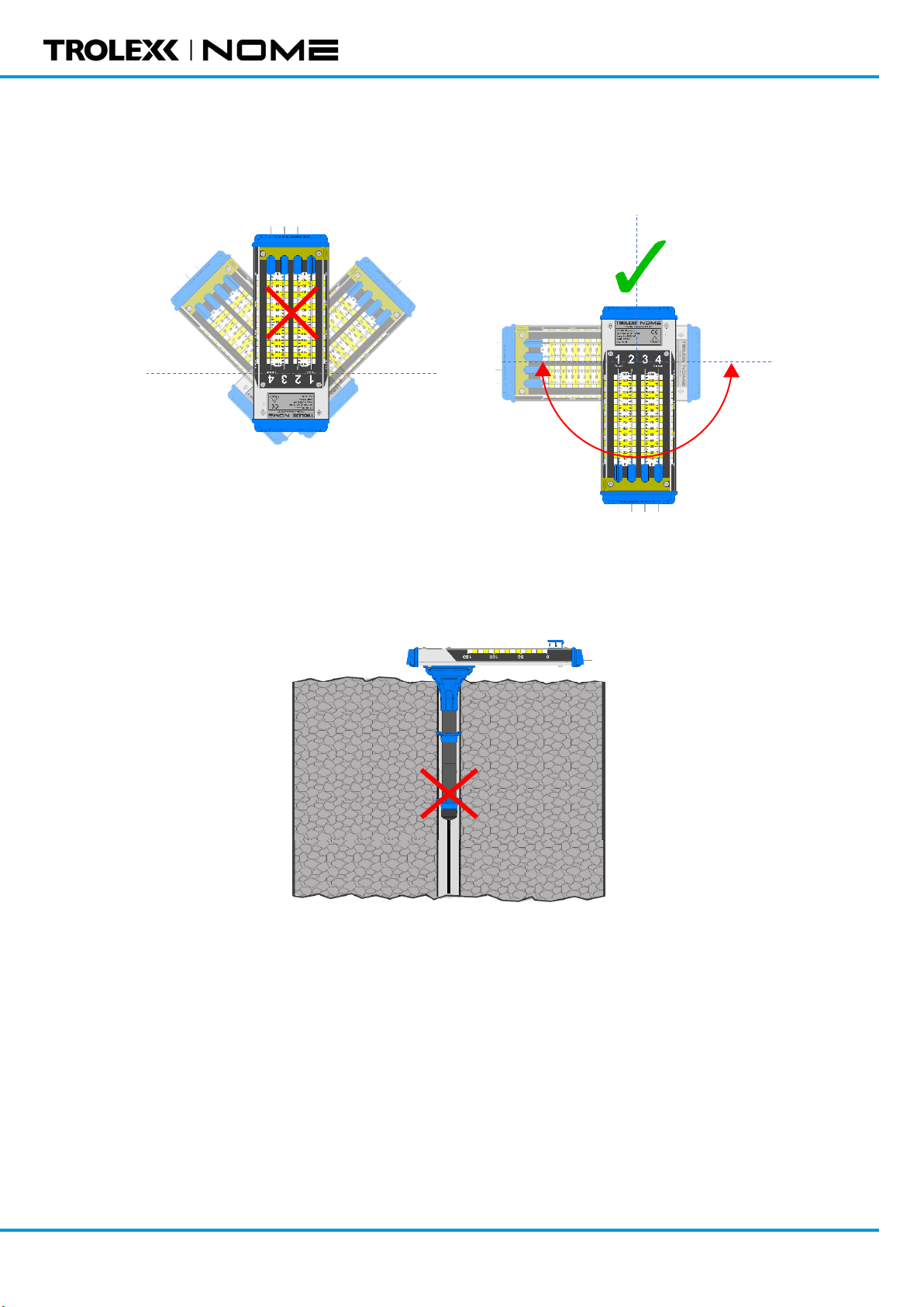
Telltale Orientation
It is important to consider the appropriate installation orientation of individual Telltales when fitting
or expanding a RockMonitor XM system. Telltale devices have been designed to allow for various
installation options when mounting into a mine roof or sidewall whilst offering the maximum
protection from unnecessary ingress. Please follow the orientation installation guide below.
Roof Mounting
A device can be mounted directly into the mine roof with the Telltale body being positioned in any
degree of angle about the bore hole centre. It is recommended to orientate the device so that it is
perpendicular with the walls of the roadway. This will allow for the side scales on the device and the
anchor indicators to be viewable down the roadway from both sides.
Roof Mounting Orientation
Sidewall Mounting
A device can be mounted directly into a mine sidewall with the Telltale body being positioned in a
fixed orientation about a 180-degree angle around the bore hole centre. It is recommended to
orientate the device so that the scale label is on or below a horizontal installation position to ensure
suitable in-situ ingress draining takes place.
Sidewall Mounting Orientation
www.trolex.com
15 P5625.1607 Rev A
During sidewall mounting, the device should never be installed with the scale label positioned above the
horizontal installation level.
Incorrect sidewall Telltale mounting
Telltales must never be installed with the bore tube pointing down.
Inverted device mounting
RMXM Telltale User Manual
www.trolex.co
m
P5625.1607 Rev A 16
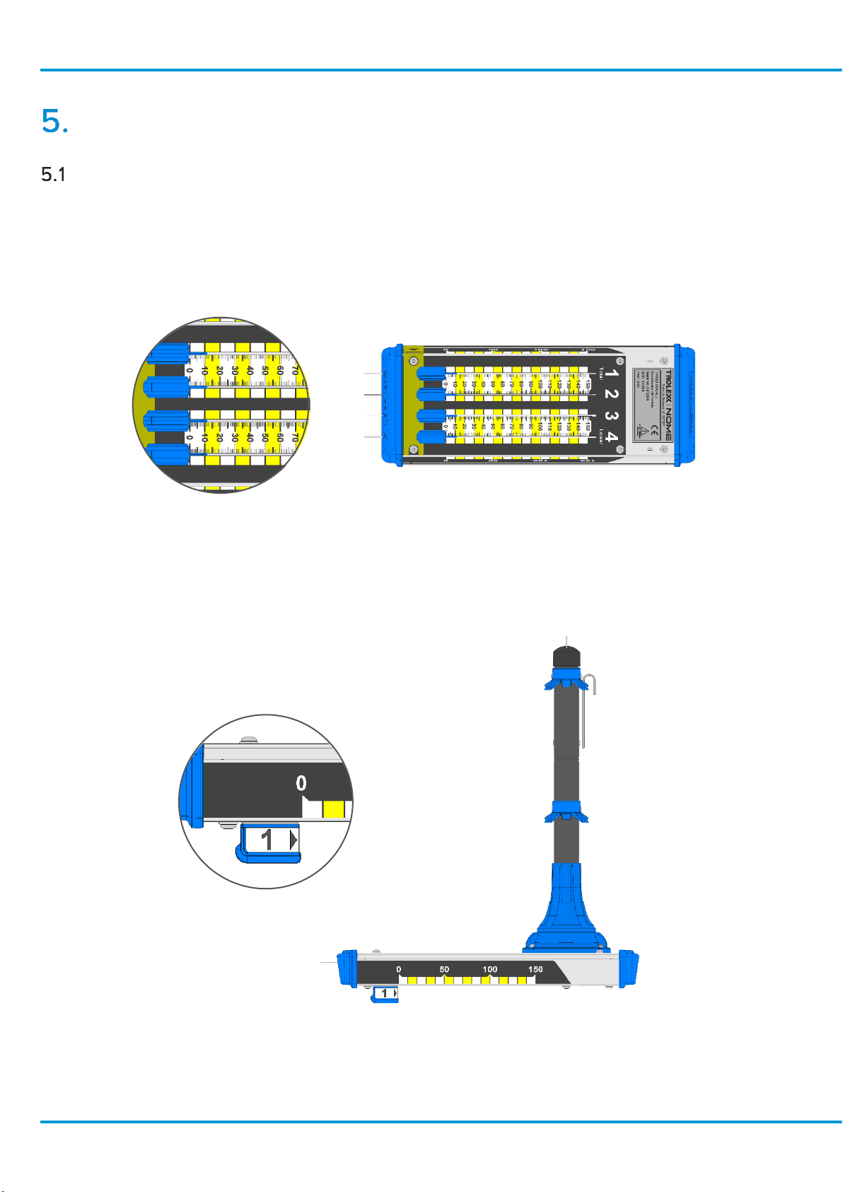
General Operation
Measuring Displacement
The Telltale provides local indication of displacement by way of linear scales on the device. These are
provided as a high visual indication and there are two types of visual scale on the device:
1.
A fine scale on the underside of the device which provides measurement of displacement to
the millimetre. The scale should be read from the leading (front) face of the anchor indicators.
2.
A course scale on the sides of the device. These are intended to provide general indication of
displacement from a distance in increments of 10mm. Viewing of the side scale from any angle
other than perpendicular will result in an inability to judge displacement with any accuracy.
www.trolex.com
17 P5625.1607 Rev A
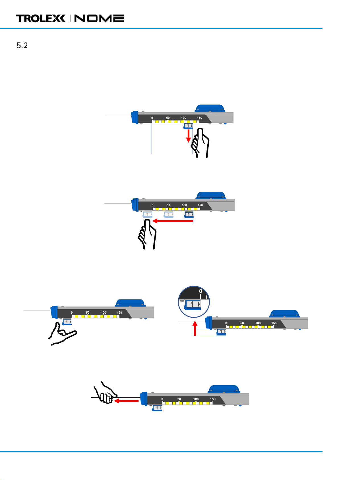
Extending the Measurement Range
The Telltale has a measurement range of 0 to 150mm, however this range can be extended if required.
There is facility to manually reset the anchor indicators back to 0 to allow for further travel whilst
maintaining the current readings. To reset the telltale, follow the procedure below:
1.
On the telltale itself, pull the reset handle down
2.
Whilst holding the handle down, slide the handle back to the zero position on the scale.
3.
Release the handle. Ensure the handle snaps upwards against the device and is not stuck in
the down position.
4.
Pull on each cable coming out of the device to remove slack in the line.

RMXM Telltale User Manual
www.trolex.co
m
P5625.1607 Rev A 18
Maintenance
The maintenance of the product must only be carried out by competent personnel. Maintenance
shall be considered with reference to the local safety regulations and authorities. Refer to the
following standards for additional guidance:
•
IEC/EN 60079-17
The product shall only be serviced and repaired by Trolex Ltd., or a local Trolex service agent
approved by Trolex Ltd. in order to maintain the certification of the product.
Visual Checks
Periodical visual checks should be carried out to assess if there are any issues arising with the
Telltales. Check for:
1.
Labels on the device are still in place and are not peeling or discolouring. Ensure all labels are
clean by following 8.2 below.
2.
Check for any damage to the device. Plastic parts should not be cracked or broken which could
affect IP rating of the device. The metal housing should not be dented or bent which could cause
issues with the mechanical mechanism.
3.
Check that the device is still fitted tight against the roof and has not slipped down in the bore
hole.
Cleaning Labels
It is recommended to clean the device periodically to ensure linear scales and indicators are clean
and readable. The product should only be cleaned with a damp cloth.
Check Mechanism for Seizure or Jamming
Periodically check that the spring mechanisms on the displacement indicators are able to move
freely. This can be done by pushing each indicator forward a little and releasing. The indicator should
slide back freely to its original position and not stick in place.
Replacing Telltales
The telltale is designed to be a one-time fit into the bore hole, due to the retention required to hold
the device in place. If a faulty instrument does need to be removed from a bore hole, then this is
possible, but it would require a high degree of force to extract. Take any relevant precautions when
doing this to minimise the risk of injury.

www.trolex.com
19 P5625.1607 Rev A
System Troubleshooting and Diagnosis
Reset Handle
The reset handle is part of a spring-loaded mechanism designed for releasing the handle from the
anchor wire to allow it to be moved back to zero.
•
If the reset handle is difficult to pull down it is not recommended to apply too much force to pull
it. Use one hand to brace against the metal body of the device and another to pull the handle
down.
If the handle does not snap back into the up position it could also be due to dust ingress. Do not
leave the handles stuck in the down position as this means the anchor wire may not be clamped and
displacement may not be measured. The handles can be pushed up manually if required, once they
are against the body of the device the anchor wire will be clamped.
Technical Support
Our technical services team are available to provide expert ongoing technical assistance and
technical support packages tailored to your specific requirements.
Please contact our technical services team:
Trolex
Tel: +44 (0) 161 483 1435
Email: servic[email protected]
Nome Services
Tel: +61 (0) 437 754 904
Email: service@nomeservices.com.au
Table of contents
Other Trolex Measuring Instrument manuals

Trolex
Trolex TX6386 User manual

Trolex
Trolex Air XS User manual

Trolex
Trolex TX6377 User manual

Trolex
Trolex XD One User manual

Trolex
Trolex Nome TX5001 RockMonitor XR Telltale Installation and operating manual

Trolex
Trolex Air XS User manual

Trolex
Trolex TX6377 User manual

Trolex
Trolex TX6353 User manual

Trolex
Trolex XD1+ User manual


