Trolex Air XS User manual

1
USER MANUAL
LET’S GET REAL
REALTIME RCS DETECTION

CONTENTS
1General description............................................................................................................................................1
1.1 Main features........................................................................................................................................................2
1.2 Limits of use..........................................................................................................................................................2
2 Product safety.....................................................................................................................................................3
3Danger from process........................................................................................................................................4
4 Safety procedures.............................................................................................................................................5
4.1 Laser safety precautions..................................................................................................................................5
5 System components..........................................................................................................................................7
5.1 TX8100 Air XS RCS Monitor.............................................................................................................................8
5.2 Particulate flow path..........................................................................................................................................9
5.3 Peripherals and accessories...........................................................................................................................10
6Certification.........................................................................................................................................................11
6.1 Compliance..........................................................................................................................................................11
7Technical information......................................................................................................................................12
7.1 Product specification........................................................................................................................................12
7.2 Product dimensions..........................................................................................................................................14
8Hardware installation......................................................................................................................................15
8.1 Safety precautions.............................................................................................................................................15
8.2 Mounting details...............................................................................................................................................16
8.3 Electrical connections......................................................................................................................................17
8.4 I/O terminals........................................................................................................................................................18
8.5 Power connections............................................................................................................................................18
9Commissioning..................................................................................................................................................19
9.1 First power on......................................................................................................................................................19
9.2 System shutdown...............................................................................................................................................19
9.3 First-generationfunctionality..........................................................................................................................20
9.4 Application software.........................................................................................................................................20
10 Controls and indicators..................................................................................................................................21
10.1 Navigation............................................................................................................................................................21
11 General operation............................................................................................................................................22
11.1 User interface display.......................................................................................................................................22
11.2 Particulate display information......................................................................................................................23
12 Instrument configuration...............................................................................................................................25
12.1 Default settings..................................................................................................................................................25
12.2 On-site configuration........................................................................................................................................25
12.3 Custom alarms....................................................................................................................................................25
13 Updating firmware...........................................................................................................................................26
14 Maintenance.......................................................................................................................................................27
14.1 Visual checks......................................................................................................................................................28
14.2 Cleaning labels...................................................................................................................................................28
14.3 Particulate entry/exit apertures......................................................................................................................28
14.4 Filter replacement..............................................................................................................................................29
14.5 Warranty................................................................................................................................................................29

15 Troubleshooting...............................................................................................................................................30
15.1 High temperature operating..........................................................................................................................30
15.2 Fault codes.........................................................................................................................................................30
16 Glossary and definitions.................................................................................................................................31
17 Disposal..............................................................................................................................................................32
18 Get in touch.......................................................................................................................................................33
18.1 Feedback............................................................................................................................................................33
Disclaimer...........................................................................................................................................................33
Trademark...........................................................................................................................................................34

AIR XS USER MANUAL1
1. GENERAL DESCRIPTION
The first-generation Trolex Air XS Silica Monitor is designed to provide detailed, accurate,
real-time data on airborne RCS content based on the chosen installation environment. Using
innovative Optical Refraction Technology (ORT), the Air XS combines a consistent particle flow
rate with advanced sensing technology to provide information on airborne dust mixtures.
As the Air XS processes and analyses particulate data, an adaptive algorithm is used to
calculate and identify the average level of RCS from the overall particle count. Measurement
information can be viewed via the instrument display or as historical readings using the
accompanying Trolex Breathe application software.

2
1.1 Main features
To ensure the optimum performance and safe operation, the Air XS must be operated as per the
limits detailed in the technical data section of this user manual. Operation outside these limits may
result in damage to the equipment or failure to achieve the performance specification.
Continual operation of the Air XS at extremes of the specified temperature limits may reduce the
operating lifetime of the product.
Trolex will not be liable for any injury or damage caused by incorrect installation, setup,
operation, or maintenance resulting in a failure to follow the procedures and safety instructions
provided in this user manual.
Real-time continuous measurement of atmospheric RCS concentration
Real-time continuous measurement of dust particle count
On-device display readout
High-reliability and low-maintenance
High visibility alarm warning indicators
‘Plug and play’ installation
1.2 Limits of use

3 AIR XS USER MANUAL
2. PRODUCT SAFETY
The following symbols are used in this manual or on the instrument to indicate procedures
that, if not followed correctly, may result in personal injury or damage to equipment.
In addition, the following symbols are used on the instrument
Alerts the user to a potentially hazardous procedure or practice
which, if not followed correctly can result in serious personal injury or
injury of others.
WARNING!
Alerts the user to a procedure or practice which, if not followed
correctly, can result in damage to the system or ancillary equipment.
The use of controls, adjustments, or procedures other than those
specified in this user manual may result in exposure to hazardous
optical radiation.
WARNING! – LASER RADIATION
CAUTION!
WARNING! – ELECTRIC SHOCK RISK

4
It is possible that the Air XS could be installed in environments that contain process particulates
which can be hazardous to health.
Unless process conditions are known to be entirely safe, suitable precautions such as the use of
breathing apparatus or environmental purging/detoxifying should be employed before entry is
made into the installation or maintenance environment.
3. DANGER FROM PROCESS
Note: This product variant is not designed for use within designated hazardous areas.

AIR XS USER MANUAL5
Always observe the safety precautions detailed in this user manual. Personnel installing, operating,
or maintaining the equipment are responsible for their personal safety and correct handling of the
equipment in accordance with all safety instructions detailed.
Follow all warnings and instructions marked on the instrument. Warning labels are situated on the
instrument, indicating a hazard at or near the location of the warning label.
Retain these instructions in a safe and known place for future use.
The Air XS has been designed to be as simple to install and commission as possible. Nevertheless,
installation in working environments can be challenging and correct set up is critical to the function
of the instrument. It is important that you carefully read the entire User Manual before using and
installing the Air XS for the first time and keep it in a safe place for future reference.
Peripheral components such as the power supply and communications module/peripheral or
interface must be installed according to the manufacturer’s instructions and the installation
location’s prevailing statutory regulations.
The installation of the instrument must only be carried out by competent personnel. Each
installation needs to be considered with reference to the local safety regulations and authorities.
Observe the national safety regulations issued, for example, by the employers’ liability insurance
association, social security institutions, occupational safety and health or other safety authorities.
4. SAFETY PROCEDURES
The Air XS is rated via the Class 1 ‘Laser Safety Guideline’ under all conditions of normal use.
Class 1 laser products may contain laser systems of a higher class but there are adequate
engineering control measures to ensure that access to the beam is not permitted during normal
use.
4.1 Laser safety precautions
WARNING – Class 3B laser radiation: do not open the laser
housing when the laser is powered on as it may result in eye
damage from directly viewing the laser beam.

6
Sensor housing
WARNING – There are no user servicable parts
inside the Air XS. Servicing should only be carried out by Trolex or
an approved service technician.

AIR XS USER MANUAL7
The Air XS is typically installed as a stand-alone instrument for general purpose applications. The
instrument is supplied with peripherals fitted to allow for the plug and play installation to universal
mains/DC power supplies and data outputs.
The instrument and Trolex Breathe software are specifically designed to work in conjunction with each
other using proprietary protocols and design features. The system has, however, been designed to
support third-party power supplies and communication protocols where required.
Note: M20 gland entries are provided for custom installation requirements. Gland entries may be
blanked, and installations may vary from diagram shown.
5. SYSTEM COMPONENTS
Example installation configuration
Windows PC
or server
USB interface port
AC or DC power supply

8
5.1 TX8100 Air XS Silica Monitor
The Air XS RCS monitor uses a custom particle sensor that is located inside a robust stainless-steel
housing. This provides isolation and ingress protection between the particle flow path and the main
control circuits. Control circuits are housed in a lockable, IP66 rated steel enclosure. Information
and settings can be accessed using the keypad and display located on the front of the instrument.
The figure below shows the location of the navigation buttons, display screen and status LEDs.
Power and network connections enter the main housing via cable entry glands located on the
bottom of the instrument. The Air XS can be wall or stand mounted via the integrated external
mounting brackets.
Particle inlet
Door lock
Navigation buttons
LCD
Status
Mounting brackets M20 cable
entry glands
USB interface

AIR XS USER MANUAL9
The Air XS has been designed with the ability to restrict ingress through the particulate flow path
during routine maintenance and cleaning periods. A rotational top cap is used to open or close the
particle flow path to provide ingress protection during cleaning.
It is recommended that the top cap is set to the closed position during instrument maintenance
and cleaning to ensure the dust sensor is not exposed to unnecessary ingress. When the top cap is
rotated into the closed position, the Air XS conforms to IPX6.
5.2 Particle flow path
Note: Rotate the top cap to move between ‘open’ and ‘closed’ positions.

10
The Air XS can be connected to a standard 100V - 240V AC power supply OR a 9 – 18V dc power
supply. Before connecting a power supply to the instrument, ensure that the supply source is
compatible with the instrument and information outlined on the appropriate rating plate. See below
for rating plate details:
Power supply
5.3 Peripherals and accessories

AIR XS USER MANUAL11
6. CERTIFICATION
The Air XS complies with the following European Union
Directives:
Electromagnetic Compatibility (EMC) Directive 2014/30/
EU
- EN 61326-1:2013
Low Voltage Directive (LVD) 2014/35/EU
- EN 61010-1:2010+A1:2019
6.1 Compliance
The Air XS complies with the following RoHS Directives:
- RoHS Directive 2002/95/EC
- RoHS 2 Directive 2011/65/EU

12
As applications of use are outside our control, the information provided is given without legal
responsibility. Customers should test under their own conditions to ensure that the unit is suitable for
their own requirements.
UK 50 100
Thorlabs Aus
AES
7. TECHNICAL INFORMATION
7.1 Product specification
Sensing technology Optical Refraction Technology (ORT)
Light-Scatter Photometer (OPC)
Particulate measurement Target RCS identification range 1m – 10m
Max. typical dust loading* 150mg/m
Continuous range 25mg/m
Displayed data RCS mg/m
Total particles/litre
Resolution 1,000 of a mg
Averaging period 15 minutes, 1 hour, 4 hours, 8 hours and 12 hours (rolling avg.)
Sampling interval 1– 60 seconds
Particle count >600 particles/second
Total airflow rate ~1.5L/m (nominal)
Typical RCS accuracy +/- 25%
*The instrument can define particulate measurement peak trends up to the quantity specified.
Note: Sustained exposure to dust quantities above 25 mg/m will be logged; however, it may aect
the operating life of the Air XS sensor.
Particulate sensing parameters

AIR XS USER MANUAL13
Technical specification
Operating temperature -10°C to +45°C
Humidity 0 – 95% RH (non-condensing)
Housing material PC/ABS – stainless steel
Ingress protection Main enclosure: IP65
Particle flow path, cap open: IP42
Weight 8.2kg
Cable entries 3x M20 with removable blanks
1x M20 breather gland
1x M20 USB connector
Nominal power supply 100V to 240V AC 50/60Hz
9 to 18V DC
Power consumption 15W
Communications RS485 data output with MODBUS RTU protocol
Ethernet (MODBUS TCP/IP)
External power output 15V 1A for powering external devices (e.g. 4G modem)
3V3 1A
Connectivity Trolex Breathe PC application
Data download External USB interface
Instrument data storage 6GB
User interface 128x64 dot matrix display with RGB backlight
Navigation keypad (Membrane)
Visual alarms Custom alarm set points
Latching/non-latching
Indicators 1x Green High Brightness LED – Sensor heartbeat
1x Blue High Brightness LED – Communications
Self-test routine Sensor hardware, Circuitry and Communications on ‘power on’
Manual self-test during use
Certification CE compliant

14
7.2 Product dimensions
Note: Rotate the top cap to move between ‘Open’ and ‘Closed’ positions.
305mm
Panel key
387mm
305mm 156mm

AIR XS USER MANUAL15
8. HARDWARE INSTALLATION
Refer to section 4 of this user manual before undertaking the installation of the Air XS device. The
installation location of the Air XS device is the prerogative of the installer and care should be taken
to ensure an appropriate position has been selected. Consider the location of a suitable power
supply and external fuses, access to a communications network and the protection of cabling from
damage.
8.1 Safety precautions
1. Secure the Air XS to a suitable mounting surface using the integrated
mounting brackets.
2. Ensure that the Air XS is mounted in an upright position.
3. Unlock and open the enclosure door to access the internals of the
enclosure.
4. Ensure power is isolated before making electrical connections to the
instrument.
5. Power supply voltage and frequency must match the instrument (refer to
rating plate).
6. Ensure external switches or fuses are installed where applicable.
7. Run the required cables through the cable glands provided in the bottom of
the enclosure.
8. Wire the cables into the relevant terminals as indicated on the internal plate (refer to
section 8.3).
9. Tighten the cable gland against the cable to ensure an IP seal.
10. Close and lock the door after use to maintain IP rating of the enclosure.
11. Ensure that the particulate entry and exit ports are not restricted or covered.
Note: The instrument is susceptible to ingress when the door is open so care must be taken to ensure
the location is clean during installation.

16
8.2 Mounting details
Note: Ensure the Air XS is mounted vertically during installation.
The figure and tables below detail the connections available internally in the Air XS. The connections
can be accessed by opening the front housing of the instrument using the supplied key.
4x M10

AIR XS USER MANUAL17
AC power DC power
LN
Power
1 2 3
V+
Power
12 3
0V
AC power in DC power in Outputs
1
2
3 6
5
4 7
8
9
10
Supply voltage Supply voltage
0V return 0V return
Earth Earth
RS485/USB switch
RS485 B
RS485 A
RS485 0V
11
12
13
14
15
16
V out
0V
V out
V out
USB
Ethernet
Table 1: Power, RS485, External power, USB and Ethernet terminal connections.
8.3 Electrical connections
Other manuals for Air XS
1
Table of contents
Other Trolex Measuring Instrument manuals

Trolex
Trolex TX6386 User manual

Trolex
Trolex TX6377 User manual
Trolex
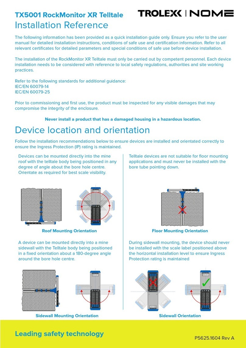
Trolex Nome TX5001 RockMonitor XR Telltale Installation and operating manual

Trolex
Trolex TX6377 User manual

Trolex
Trolex TX6353 User manual

Trolex
Trolex XD One User manual

Trolex
Trolex Air XS User manual

Trolex
Trolex XD1+ User manual
Trolex
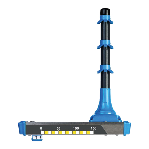
Trolex RockMonitor XM Telltale TX5021 User manual
