TROMMELBERG TXB30Y User manual

USER MANUAL TXB30Y, V16.01 page | 1
Technical changes, misprints and errors are reserved
USER MANUAL
Scissor Lift
TXB30Y

USER MANUAL TXB30Y, V16.01 page | 2
Technical changes, misprints and errors are reserved
The manual is an integral part of the lift, which it should always accompany even if the
unit is sold .The manual, must be kept in the vicinity of the lift in an easily accessible
place so that the operator and maintenance staff must be able to locate and consult the
manual quickly at any time.
ATTENTIVE AND REPEATED READING OF SAFETY INSTRUCTION, WHICH
CONTAINS IMPORTANT INFORMATION AND SAFETY WARNINGS, IS
PARTICULARLY RECOMMENDED.

USER MANUAL TXB30Y, V16.01 page | 3
Technical changes, misprints and errors are reserved
Table of contents
Safety page 4-7
Introduction page 4
Symbols page 4
Intended Use page 4
Correct Use page 4
Safety Instructions for Commissioning page 5
Safety Instructions for Operation page 5
Safety Instructions for Maintenance page 6
1. Specifications page 8
Storage page 9
Opening the packaging page 9
2. Transportation page 9
3. Unpacking page 10
4. Installation site, foundation
and required supply connections page 10-11
5. Installation und testing page 11-15
6. Maintenance page 16
6.1. Maintenance schedule page 16
7. Operation page 17-20
7.1. Defects / Maulfunctions page 17
7.2. Controls page 18
7.3. Operation page 19-20
7.3.1. Preparations page 19
7.3.2. Raising page 19
7.3.3. Vehicle in Raised Position page 19
7.3.4. Lowering page 20
7.4. Protection against Unauthorized Usage page 20
8. Troubleshooting pege 21
9. Hydraulic Systems page 22
10.Pneumatic Systems Page 23
11.Electrical Systems page 24-25
12.Exploded view page 26-32

USER MANUAL TXB30Y, V16.01 page | 4
Technical changes, misprints and errors are reserved
Safety
Introduction
Thoroughly read this manual before operating the lift and comply with the instructions.
Always display the manual in a conspicuous location.
Personal injury and property damage incurred due to non-compliance with these safety
instructions are not covered by the product liability regulations.
Symbols
Failure to comply with instructions could result in personal injury.
Failure to comply with instructions could result in property damage.
Risk of electrical shock
Important information
Intended Use
The scissor lift TXB30Y has a lifting capacity of 3000kg and can lift vehicles, which do
not exceed the lifting capacity. The scissor lift is suitable for maintenance and repair
work on vehicles.
Correct Use
- the scissor lift is designed for secure lifting of motor vehicles
- never exceed the lifting capacity of the scissor lift TXB30Y
- the center-of-gravity of the vehicle has to be placed directly in the middle of
the lift
- always pay attention to an equal weight distribution!
- the vehicle has to be driven as centrally as possible on the lifting platforms

USER MANUAL TXB30Y, V16.01 page | 5
Technical changes, misprints and errors are reserved
Safety Instructions for Commissioning
The lift may be installed and commissioned by authorized service personnel,
only.
The standard lift version may not be installed and commissioned in the vicinity of
explosives or flammable liquids.
The standard lift version may not be installed and commissioned outdoors or in
moist rooms (e.g. car wash).
Safety Instructions for Operation
Carefully read the User Manual.
Lift operation by authorized personnel over 18 years, only.
Always keep the lift and lift area clean and free of tools, parts, debris etc.
Once the pads contact the lifting points of the vehicle, check if the pads are in the
correct position.
After raising the vehicle briefly, stop and check the pads for secure contact.
Always lift the vehicle using all four pads!
Make sure the vehicle doors are closed during raising and lowering cycles.
Closely watch the vehicle and the lift during raising and lowering cycles.
Do not allow anyone to stay in the lift area during raising and lowering cycles.
Climbing up the raised lift or vehicle is prohibited.
Only use the lift for its intended purpose.
Comply with the applicable accident prevention regulations.
Do not overload the lift. The rated load capacity is indicated on the lifts nameplate.
Only use the vehicle manufacturer´s recommended lifting points!
After positioning the vehicle, apply the parking brake.
Use caution when removing or installing heavy components (center-of-gravity
displacement)!
The main switch also serves as EMERGENCY SWITCH. In case of emergency
turn it to the position “0”.
Protect all parts of the electrical equipment from humidity and moisture.
Protect the lift against unauthorized usage by padlocking the main switch.

USER MANUAL TXB30Y, V16.01 page | 6
Technical changes, misprints and errors are reserved
Safety Instructions for Maintenance
Maintenance or repair work by authorized service personnel, only.
Turn off and padlock the main switch before doing any maintenance, or repair
work.
Work on pulse generators or proximity switches by authorized service personnel,
only.
Work on the electrical equipment by certified electricians, only.
Ensure that ecologically harmful substances are disposed of, only in accordance
with the appropriate regulations.
Do not use high pressure / steam jet cleaners or caustic cleaning agents. Risk of
damage!
Do not replace or override the safety devices.
The MSDS of the hydraulic oil* shall be obtained and kept at the easily
accessible place for reference in the emergency situation.
*Hydraulic oil is not included in the scope of delivery
* we recommend the use of HLP32 or HLP46 hydraulic oil
The safety instructions help you to prevent injuries or damages. For your safety, the
compliance with this safety instructions is absolutely necessary. The relevant national
and international safety standards for occupational health and safety must be observed.
Each operator is responsible for the compliance with the rules applicable to himself and
has to organize the latest version of the regulations independently.
The installation and commissioning may be performed by authorized service personnel,
only. The installation and commissioning is described in this manual.

USER MANUAL TXB30Y, V16.01 page | 7
Technical changes, misprints and errors are reserved
Never use this scissor lift, without observing the safety instructions.
- always pay attention to free lifting paths
- always make sure that there is nobody in or under the vehicle during the
raising or lowering cycles
- always make sure that there are no parts, tools or limbs in the scissor
mechanism
- always make sure that the vehicle is driven in the predetermined direction to
the lift!
- always pay attention on the correct positioning of the vehicle to be lifted!
- always make sure that there are no persons on the lift or in the vehicle during
the raising or lowering cycles!
- to prevent slipping, keep your working area free from dirt, oils or other
lubricants
Drive direction

USER MANUAL TXB30Y, V16.01 page | 8
Technical changes, misprints and errors are reserved
1. Specifications
TXB30Y
Lifting capacity
3000Kg
Lifting height
1850mm
Min. height
105mm
Lifting time
55-60s
Motor power
2.2kW
Power supply
3/N/PE~380V, 50Hz,10A
Net weight
883Kg
Noise level
< 76 dB

USER MANUAL TXB30Y, V16.01 page | 9
Technical changes, misprints and errors are reserved
Storage
Packed machinery must always be kept in a covered, protected place, at a temperature
between -10°C and +40°C and must not be exposed to direct sunlight.
Opening of the packaging
When the lift arrives, check that the machine has not been damaged during transport and
that all parts are present. The packaging must be opened using all possible
precautionary measure to avoid damaging the machine or its parts. Make sure that parts
do not fall out of the packaging during the opening.
2. Transportation
For the easy transport, the PACKAGES are bolted together with a belt. The PACKAGES
must be separated by any suitable means.
Moving and positioning can be very dangerous, if not performed with the
utmost caution. Check the integrity and suitability of the available means.
All packaging, lifting, handling, transport and unpacking operations are to
be performed by authorized personnel with knowledge of the lift and the
contents of this manual.

USER MANUAL TXB30Y, V16.01 page | 10
Technical changes, misprints and errors are reserved
3. Unpacking
Check that the equipment is in perfect condition, making sure that no parts are damaged
or missing. If in doubt, do not use the machine and contact your retailer.
4. Installation site, foundation and required supply connections
Installation site
The scissor lift TXB30Y must not be installed and commissioned in the vicinity of
explosives or flammable liquids and outdoors or in moist rooms (e.g. car wash).
In rooms with low ceilings the installation of height safety shutdown is recommended.
The operator is responsible for the selection of a suitable installation site.

USER MANUAL TXB30Y, V16.01 page | 11
Technical changes, misprints and errors are reserved
Foundation
The car lift must be installed according to the specified safety distances from walls. The
safety distances from walls must be 1000 mm at least, taking into consideration the
necessary space to work easily. Because space for the control unit and for possible
runways in case of emergency is also necessary. The room must be previously arranged
for the power supply and pneumatic feed of the car lift. The room must be 4000 mm in
height, at least.
The car lift can be placed on any floor, as long as it is perfectly level and sufficiently
resistant (≥250kg/cm², the thickness of concrete ≥200mm).
All parts of the machine must be uniformly lit with sufficient light to make sure that the
adjustment and maintenance operations can be performed safely, and without reflected
light or glare, that could give rise to eye fatigue.
Required supply connections
Three-phase electric power supply
400 V, 50 Hz three phase current (3~ + N + PE 400 V, 50 Hz).
The diameter of the cable must be adapted to the type of the lift and the local
conditions.
Pneumatic feed
permanent working pressure 6-8 bar!
USER MANUAL TXB30Y, V16.01 page | 12
Technical changes, misprints and errors are reserved
5. Installation and testing
1. Take out the machine from the packaging and place it on the ground
(intended installation site). Anchor the platforms in the foundation, when
all connections fit properly and the position is finally determined.
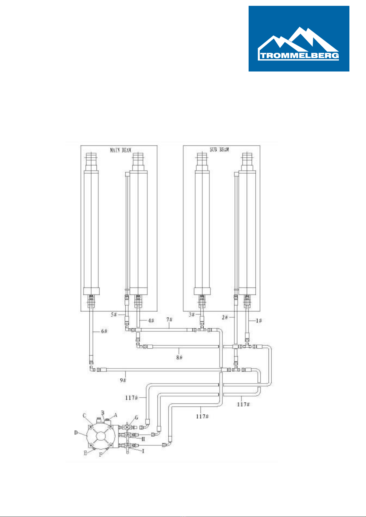
2. Connect the hydraulic lines according to the connection diagram.

USER MANUAL TXB30Y, V16.01 page | 13
Technical changes, misprints and errors are reserved
3. Connect the pneumatic hose (ø8x6) to the solenoid valve in the control
box. (pneumatic feed line)
4. After the connection of the pneumatic feed line, connect the pneumatic
lines to the air pressure cylinders in each platform.
(page 23, chapter 10 Pneumatic Systems)
ATTENTION: It must be ensured, that the pneumatic hoses cannot be
pinched during raising and lowering cycles.
USER MANUAL TXB30Y, V16.01 page | 14
Technical changes, misprints and errors are reserved
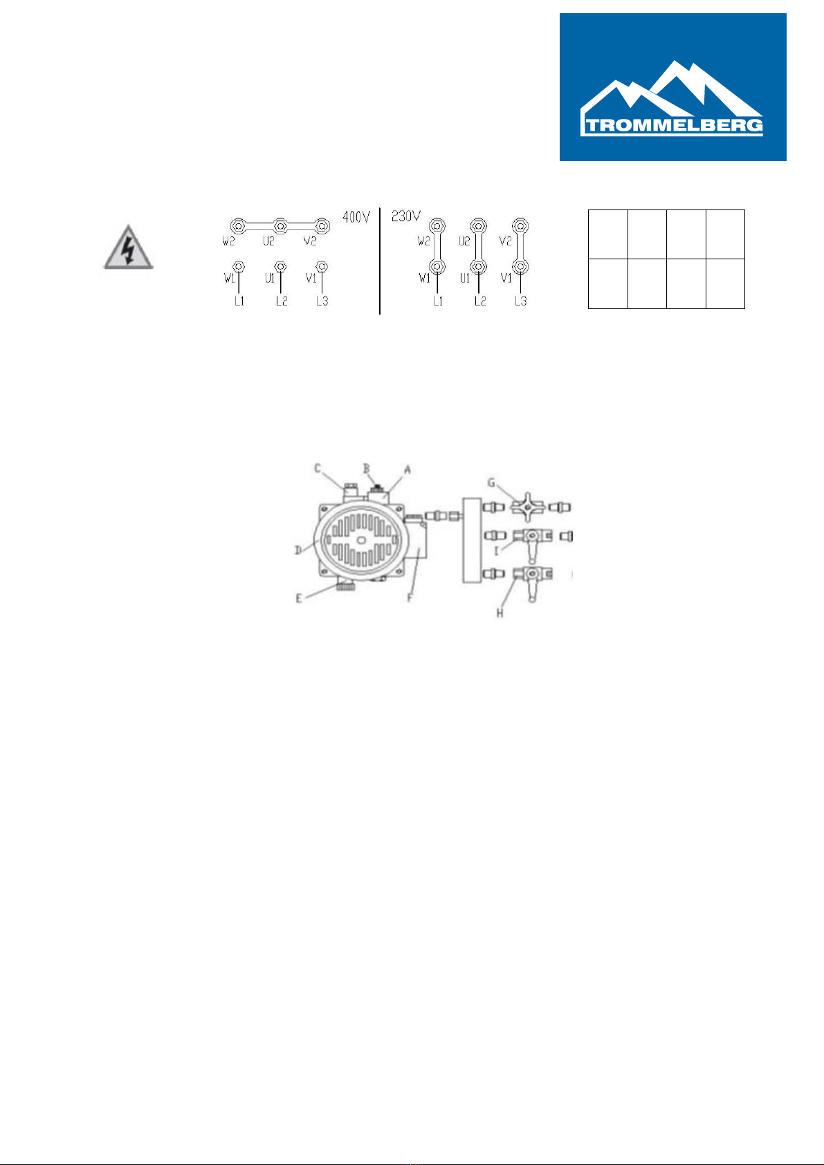
5. Connect the electrical connections according to the template shown below:
6. After the connection of the hydraulic lines, pneumatic lines and the
electrical power supply, add 18 to 20 liters hydraulic oil* into the oil tank.
7. Venting of the hydraulic system:
- open all 3 valves (valve G, anticlockwise 2 full turns, valve I and H at
90°)
- press the „UP“ button to raise the lift to the max. height
- valve I and H have to be closed now!
- then open the venting screws of the main cylinders (at first on the
main platform, then on the sub platform), to vent the hydraulic system
- tighten the venting screws and press the „DOWN“ button to lower the
lift to its lowest position
- repeat the venting operation until the hydraulic system is completely
vented (about 2-3 repetitions)
*Hydraulic oil is not included in the scope of delivery
1
3
4
5
PE
L1
L2
L3

USER MANUAL TXB30Y, V16.01 page | 15
Technical changes, misprints and errors are reserved
8. Adjustment of the synchronism:
- If the adjustment of the synchronism is necessary, perform the
following steps
oraise the lift to its max. height, to determine the actual amount
of difference between the two platforms
othe valve (I or H) of the lower platform remains closed at all
time
onow press the „DOWN“ button and open the valve (I or H) of
the higher platform at the same time
oas soon as both platforms are at the same level, close the
previous opened valve (I or H)
owhen both valves (I and H) are closed again, press the
„DOWN“ button to lower the lift to its lowest position
oraise the lift to its max. height and observe the synchronism of
the platforms
oif there are still height differences, repeat the previous
described steps, as long as the synchronization is guaranteed
for 100%
- After the adjustment of the synchronism you can use the lift to lift
vehicles, which does not exceed the max. lifting capacity
9. Working conditions:
- Ambient temperature between 5°C - 40°C.
- Relative humidity between 30-95%
(non condensing!)
- Transportation and storage temperature shall be between -25°C –
+55°C and short period, not exceeding 24 hours at up to +70°C.
- Installation altitude max. 1000m
10.Disposal of the hydraulic oil* according to the appropriate local
environmental regulations, only.
*Hydraulic oil is not included in the scope of delivery

USER MANUAL TXB30Y, V16.01 page | 16
Technical changes, misprints and errors are reserved
6. Maintenance
Turn off and lock the main switch before you start with the
maintenance work on the lift.
The maintenance intervals indicated below apply to average
workshop use. The lift should be inspected more frequently for
severe use applications.
6.1. Maintenance schedule
Establish a periodic preventive maintenance procedure to ensure trouble free operation
and long service life.
Interval Involved parts Maintenance tasks
daily hydraulic systems - check for leaks
pneumatic systems - check for leaks
safety devices - check for cerrect function
1x per week supporting frame/ - check if the pads are in the correct position
pads - lubricate slide rail and pads
monthly hydraulic systems - check for wear and tightness
pneumatic systems - check for wear and tightness
all 6 month greasing points - check the slide rails and lubricate them if
necessary
nuts and bolts - check all nuts and bolts for correct torque,
tighten them if necessary
all 12 month hydraulic systems - check fluid level
- clean oil tank and oil filter
- change the complete hydraulic oil
- check tightness of hoses and fittings
- check hoses and fittings for leakages
During the oil changing process the lift has to be at its lowest position.

USER MANUAL TXB30Y, V16.01 page | 17
Technical changes, misprints and errors are reserved
7. Operation
Lift operation by authorized personnel over 18 years, only.
Apply the parking brake after positioning the vehicle on the lift.
Do not allow anyone to stay in the lifting area during raising and lowering cycles.
Closely watch the vehicle and the lift during raising and lowering cycles. Stop the lift
immediately, if unusual movements occur (EMERGENCY SWITCH).
Do not allow anyone to climb up the lift or to stay inside the raised vehicle.
After raising the vehicle briefly, stop and check the pads for secure contact.
Make sure that the vehicle doors are closed during raising and lowering cycles.
The movement range of load and lift must be kept free of obstacles. Remove obstacles
around the lift before working.
The weight of the car to be lifted should not be more than the lifting capacity of the lift.
If the machine is not in use (e.g. over night), bring it to its lowest position and turn off the
main switch (position “0”) and padlock it.
7.1. Defects / Malfunctions
In case of defects or malfunctions, such as jerky lift movement or
deformation of the structure, support or lower the lift immediately.
Turn off and padlock the main switch. Contact qualified service
personnel.

USER MANUAL TXB30Y, V16.01 page | 18
Technical changes, misprints and errors are reserved
7.2. Controls
The main switch is used as EMERGANCY SWITCH. In Case of
emergency turn it to position “0”!
Main switch
Main switch in position „0“: power supply is interrupted
Main switch in position „1“: lift is ready for operation
„UP“ button
Press this button to raise the lift. Hold it down until the
desired lifting height has been reached. On reaching the
maximum lifting height, the lift stops automatically.
„DOWN“ button
To lower the lift completely, press and hold the „DOWN“
button.
„LOCK“ button
To lower the platform on the mechanical safety lock completely, press the „LOCK“ button.

USER MANUAL TXB30Y, V16.01 page | 19
Technical changes, misprints and errors are reserved
7.3. Operation
7.3.1. Preparations
I. Read and understand this user manual before you start to work with it.
II. Fully lower the lift.
III. Slowly position the vehicle midway between the platforms, apply the
parking brake and leave the vehicle.
IV. Position the lifting pads under the vehicle manufacturer´s recommended
lifting points.
V. Check the 4 lifting pads for their correct position.
VI. Leave the vehicle and make sure the lfiting area is clear.
7.3.2. Raising
I. Lift the vehicle, using the vehicle manufacturer´s recommended lifting
points, only!
II. The vehicle shall always be positioned in the middle of the lift.
III. Briefly raise the lift, until the lifting pads contact the vehicle and make sure
that the pads are in the correct position and the vehicle can be raised safely.
IV. Raise the lift, using the „UP“ button, until the desired lifting height is
reached.
V. Press and hold the „LOCK“ button, until the lift is lowered to the next
mechanical safety lock.
VI. Turn the main switch to position „0“.
VII. After all safety precautions have been taken, you can begin to work on the
vehicle.
7.3.3. Vehicle in Raised Position
I. Observe all accident prevention regulations.
II. Do not allow unauthorized personnel to stay under the raised vehicle.
III. Avoid sudden movements on the vehicle.
IV. Always keep the lift free of parts and tools!
V. Fasten the vehicle to the supporting frame, using lashing straps when
removing or installing heavy components (center-of-gravity displacement).

USER MANUAL TXB30Y, V16.01 page | 20
Technical changes, misprints and errors are reserved
7.3.4. Lowering
I. Turn the main switch to position „1“ and press (and hold) the „DOWN“
button, until the lift is in its lowest position.
II. Remove lifting pads and tools and drive the vehicle off the lift.
7.4. Protection against Unauthorized Usage
I. Turn the main switch to position „0“.
II. Padlock the main switch to protect the lift against unauthorized usage.
Table of contents
Other TROMMELBERG Scissor Lift manuals

Popular Scissor Lift manuals by other brands


ALMAC
ALMAC Athena 870-BL EVO TRANSLATION OF ORIGINAL INSTRUCTIONS

Genie
Genie Z-33/18 Operator's manual

LINCOS
LINCOS U-B30 user manual

Hy-Brid Lifts
Hy-Brid Lifts III Series Operation & safety manual

WERTHER INTERNATIONAL
WERTHER INTERNATIONAL STRATOS S39 Instruction and maintenance manual

CLAS
CLAS PE 6002 manual
Beacon
Beacon BWL-100 Operation & maintenance manual

Skyjack
Skyjack SJ6832 RTE Series operating manual

Custom Equipment
Custom Equipment Hy-Brid Lifts III Series MAINTENANCE & TROUBLESHOOTING MANUAL

DINGLI
DINGLI S036-RS operators manual with maintenance information

Mohawk
Mohawk USL-6000-K manual

Rotary
Rotary SM40 Operation & maintenance manual