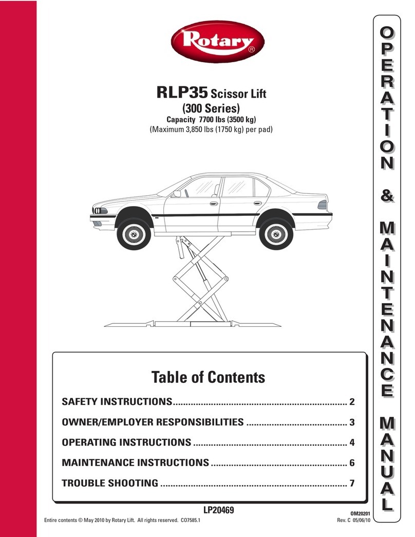
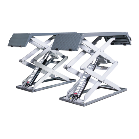
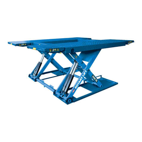
Rotary SM40 Manual

Rheinland
TUV
O
P
E
R
A
T
I
O
N
&
M
A
I
N
T
E
N
A
N
C
E
M
A
N
U
A
L
O
P
E
R
A
T
I
O
N
&
M
A
I
N
T
E
N
A
N
C
E
M
A
N
U
A
L
© March 2010 by Rotary Lift
SM40
Scissor Lifts

1
User Manual
Chapter headings page
1. Declaration of Conformity ................................................. .................................................. .................... ... ... ... 2
2. Technical characteristics ................................................ .................................................. ... ............. ... ... ..........3
3. Designation ................................................. ............................................. .............. .............. ....................... …..4
4. Expulsion of the lift ... ... ... ... ... .......................................... .................................................. .. .......... ………….5
5. Scope ... ... ... ... ... ............................................ .................................................. ......... ............. 5
6. General Safety Instructions ... ... ... ... ... ........................................... ...................................... .............. ... 7
7. Transportation ................................................. .................................................. ............... ................................. ...8
8. Unpacking ... ................................................ .................................................. .............. .................................. 8
9. Area of installation................................................. .................................................. ... .......................................... 9
10. Installation ................................................. .................................................. ............... .................................... 10
Rails and cross members
Columns
Hydraulic power unit
Connection of the hydraulic unit
11. Characteristics of the safety devices ... ... ... ............................................ ............ ................................ 16
12. Controls ... ... ... .............................................. ................................................ ........................................... 17
13. Installation ................................................. .................................................. .... ................................................. 19
14. Regular maintenance ... ... .............................................. ........................... .................................................. .. 19
15. Instructions ................................................. .............................. .................................................. ... 21
Operation of the lift
Review of the acoustic signal
Emergency stop switch
Attention
16. Manual lowering process ... ... ... ... ... ... ... ... ... ....................................... ................. ....................................... 23
The lift in the event of a power outage lowered manually
Restart the lift after a misalignment of the images
Restart the lift for a longer period, or after a cable is broken
17. Storage ... ... ... .............................................. ............................................... .................................................. .24
18. Disposal ................................................. .................................................. ..... ............................................... 24
19. Information and warnings on Oil ............................................. ...... .................................................. ... 25
20. Functional problems ................................................. ................................... .................................................. .. 26
21. Fire extinguisher ... ... ... .............................................. ............................... .............................................. ...... 27
22. Assembly (for the approved service) ... ... ... ... ... ... ... ... ... ... ... ... ... ... ... ... ... ... ... ... ... ... ... ....... 27
Circuit
Hydraulic and pneumatic circuit
Establishment of the pneumatic unit
Safety devices
Orientation of the free lift
Manual alignment of the free lift
Leveling of the main lift
Installation accessories
General routine inspection
23. Pneumatic circuit diagram ... ... ............................................... ........................ .................................................. 34
24. Hydraulic circuit diagram. ... ... .............................................. ............................. ............................................... 35
25. Electrical Schematic ... ... .............................................. ................................. ............................................. 36
26. Optional Accessories ... ... ... ... ............................................ ............................... ..................................... ........ 38
27. Installation Report ... ... ... .............................................. ............................ .................................................. ... 40
28. Regular maintenance report ... ... ... ... ... ... ... ......................................... .......... .............................. .... .... 41
29. Maintenance plan ... ... ............................................... ............................... .................................................. ..... 42
The information contained in this manual is subject to change without notice.
SM40LT-47/51
2
EG-Konformitätserklärung
EC Declaration of Conformity
im Sinne der EG-Richtlinie 2006/42/EG über Maschinen (Anhang II A)
according to EC directive 2006/42/EC on machinery (Annex II A)
Name und Anschrift des Herstellers /
Name and address of the manufacturer:
BlitzRotary GmbH
Hüfinger Str.55
78199 Bräunlingen, Germany
Diese Erklärung bezieht sich nur auf die Maschine in dem Zustand, in dem sie in Verkehr gebracht wurde; vom
Endnutzer nachträglich angebrachte Teile und/oder nachträglich vorgenommene Eingriffe bleiben unberücksichtigt. Die
Erklärung verliert ihre Gültigkeit, wenn das Produkt ohne Zustimmung umgebaut oder verändert wird.
This declaration relates exclusively to the machinery in the state in which it was placed on the market, and excludes
components which are added and/or operations carried out subsequently by the final user. The declaration is no more
valid, if the product is modified without agreement.
Hiermit erklären wir, dass die nachstehend beschriebene Maschine
Herewith we declare, that the machinery described below
Produktbezeichnung / product denomination: 4-Säulen-Hebebühne / 4-post vehicle lift
Serien- / Typenbezeichnung / model / type: SM40-47; SM40-51; SM40AT47; SM40AT-51
Tragfähigkeit 4000 kg / capacity 4000 kg
SM40LT-47; SM40LT-51
SM40LTAT-47; SM40LTAT-51
Tragfähigkeit 4000/3000 kg// capacity 4000/3000 kg
Maschinen-/Seriennummer / machinery / serial number: ………………..
Baujahr / Year of manufacture: 20…
allen einschlägigen Bestimmungen der Maschinenrichtlinie 2006/42/EG entspricht.
Die Maschine entspricht zusätzlich den Bestimmungen der Richtlinien 2004/108/EG über elektromagnetische
Verträglichkeit und 2006/95/EG über elektrische Betriebsmittel
(Schutzziele wurden gemäß Anhang I, Nr. 1.5.1 der
M
aschinenrichtlinie 200
6
/42/EG eingehalten).
is complying with all essential requirements of the Machinery Directive2006/42/EC.
In addition the partly completed machinery is in conformity with the EC Directives 2004/108/EC relating to
electromagnetic compatibility and 2006/95/EC relating to electrical equipment
(Protection objectives have been met in
accordance with Annex I No. 1.5.1 of the Machinery Directive 2006/42/EC).
Angewandte harmonisierte Normen / Harmonised Standards used
EN 1493:1998+A1:2008 Fahrzeug-Hebebühnen / Vehicle lifts
EN ISO 12100-1 : 2003 Sicherheit von Maschinen - Grundbegriffe / Safety of Machinery- Basic concepts
EN ISO 12100-2 : 2003 Sicherheit von Maschinen - Grundbegriffe / Safety of Machinery- Basic concepts
EN 60204-1:2006+7/2007 Elektrische Ausrüstung von Maschinen / Electrical equipment of machines
EN 349:1993+A1:2008 Sicherheit von Maschinen-Mindestabstände / Safety of machinery - Minimum gaps
EN ISO 13850:2008 Sicherheit von Maschinen-Not-Halt / Safety of machinery – Emergency stop
EN ISO 14121-1:2007 Sicherheit von Maschinen-Risikobeurteilung / Safety of machinery - Risk assessment
Angewandte sonstige technische Normen und Spezifikationen
Other technical standards and specifications used:
BGG 945 Prüfung von Hebebühnen / inspection of vehicle lifts
BGR 500 Betreiben von Arbeitsmitteln / management of working appliances
BGV A3 Unfallverhütungsvorschrift elektrische Anlagen und Betriebsmittel / law accident prevention regulation of
electric facilities and equipment
Bevollmächtigter für die Zusammenstellung der relevanten technischen Unterlagen:
The person authorised to compile the relevant technical documentation:
Herr Pohl; Hüfinger Str. 55; 78199 Bräunlingen
Ort /
Place :
Bräunlingen
Datum /
Date :
21.12.2009
______________________
Carsten Rohde
Geschäftsführer / Managing Director

3
2 – TECHNISCHE EIGENSCHAFTEN
capacity....................... lift............................. ........................... ........................................ 4000 kg
capacity....................... auxiliary lift.............................. .. .................................................................3000 kg
lifting time / lowering time....................lift....... .......................................appr.................. 45 Sek.
lifting time / lowering time..................... auxiliary lift........ .....................................appr........ ..........10 Sek.
power e-motor..................................................................... ........................... ..........................................................3 kW
Whole power............................................................ ........................... ............................................................3,1 kW
Electricity supply…………. .......................................... ........................... ......................230 V/400 V - Tri + PE + N - 50/60 Hz
Pneumatic supply……………....................................................................... ........................... ..................... 6/8 Bar
Capacity of the oil tank..................................................................................... ........................... ................................... 11 l.
Pressure hydraulic cycle............................................................................ ................................................................190 Bar
Net weight lift……………....................................................................... ........................... ........................ 1955 kg
Maximum volume level for the equipment leader in the job................. ........................... ............................... 70 dB(A)
Ambient temperature area …………....................................................... ........................... .................................0 bis + 50°C
Area of the relative humidity (without condensation)……………………...................................................................30 bis 95%
SIDE FACE
Dimensions in mm
PLAN VIEW
Measures SM40-LT-47

4
3 - NAME
part sescription part description
1 Auxiliary lift 11 Hydraulic power unit
2 Plattform 12 Compressed air maintenance unit
3 Fixed runway 13
4 Movable runway 14
5 Wheel Stopp () 15
6 ramp 16
7 Column with control unit 17
8 column 18
9 Grounplate of column 19
10 crossbeam

5
4 – AUSWEISUNG DER HEBEBÜHNE
If you have the model of lift, the standard number and possible additional parts ready, becomes to you the customer service of the
supplier can still give better assistance. You find the following information on the model badge:
Load capacity (kg) : 4000 (Hebebühne)
3000 (Radfreiheber)
Electric supply (V) : 230/400
Power(kW) : 3.1
Power e-motor (kW) : 3
Number of the phases: 3 + N + PE
Frequency (Hz) : 50/60
Pneumatics pressure (Bar): 6/8
5 –RANGE OF APPLICATION
This user's handbook is a component of the make.
Peruse the warning tips and instructions in this manual carefully, because this important information about the sure service of
the machines and their servicing contains.
IF THEY PRESERVE THIS MANUAL PROPERTY ON TO BE ABLE TO LOOK UPIN CASE OF NEED.
The vehicle lift SM40LT-47 / 51 is a hoist stuff for private cars and light truck with a maximum weight of 4000 kg.
Their principal purpose consists in helping by the servicing and repair of motor vehicles.
CARE
These vehicle lift is only for the inside use. It may not be used outside.
Concentrate the load not in the middle of the vehicle lift.
The load distribution must correspond to the following demands:
Main vehicle lift:
- Minimum bicycle situation of 3000 mm at least
- Distance of the front or rear base of 300 mm at least from the ends of the rolling trajectory (see fig. 1 on the page 6).
Auxiliary lift:
- maximum bicycle situation of 1700 mm at most
- Distance between the bases (in direction of the traffic) from 1200 mm at least (see illustration 2, page 6).
Abb. 1
The burden-sharing on every vehicle lift must
correspond to the topical standards:
Front / rear distribution:
-main lift:
must amount to 2/3 on the front and 1/3 at the
rear, and vice versa.
- auxiliary lift:
MODEL SM40/LT-47/51
PRODUCTION
YEAR
SERIENNR:

6
must amount to 3/5 on the front and 2/5 at the
rear, and vice versa.
left to the right of distribution:
may not exceed 10%.
Abb. 2
CARE
Provide for the fact that with the decreasing of auto parts the balance is not affected, in particular if you use the bicycle free
siphons for beginning.
CARE
It is forbidden to use the vehicle lift in explosive surroundings.
CARE
It is forbidden to lift the load only on a pavement (vehicle lift) or a platform (auxiliary lift), all the same as small the weight is,
because this can lead, otherwise, to dangerous instability between vehicle lift and vehicle.
CARE
Use the lift not for washing vehicles.
CARE
It is forbidden to use these vehicle lift for others than in this manual described purposes. Above all it is forbidden to lift people.
BLITZROTARY Ltd is not responsible for possible damages which originate on the basis of improper wrong or unreasonable use.

7
6 - GENERAL SAFETY TIPS
The vehicle lift may be served only by certified and authorized specialist staff.
Changes or modifications in the vehicle lift which were not approved before by BlitzRotary GmbH release aforesaid party from any
compensation duty, either directly or indirectly.
The removing or altering of safety devices is an offence against the European safety regulations. BlitzRotary GmbH assumes no liability for
damages which appear on account of the manipulation of these devices.
-We recommend you to make yourselves close with the help of the instructions for use with the localisation of possible anomalies.
-The use of the vehicle lift is permissible only at places at which no danger of explosion or fire risk consists.
-By accessories or optional additional parts which are used with the vehicle lift it must concern exclusively approved individual
parts.
-Ramps and absorption surface must freely be from obstacles.
-Children and animals may not stay near the vehicle lift.
-Vehicles may be raised only in the positions which were planned by the manufacturer for it.
-As a user you must pay attention to the fact that the way, as you raise the load, shows no dangers. Check after short beginning
whether the vehicle is positioned correctly and efficiently on the vehicle lift.
Observe the runways and bicycle free siphons all the time, while the vehicle lift is in movement.
It is forbidden to park, in the area of the ramps, on the driving rails or the stroke tables, while the vehicle lift is in movement.
Nobody may climb the ramp, the driving rails or the stroke tables if these are in raised position.
During the lifting nobody may be in the vehicle or on the vehicle lift.
Examine after every manoeuvre and before you work under the siphon that the vehicle lift is protected mechanically.
Hold the vehicle lift and their surroundings in absolutely clean state.
Check before use of the vehicle lift that
the warning signal functions properly.
CARE
Every kind of work, which, all the same how insignificantly, in the electrical system of the vehicle lift is carried out requires the
availability of a certified expert (see the also specific directives relevant for it).

8
7 - TRANSPORT
The transport of the device must be carried out according to the following instructions:
• Protect the hydraulic device and the switch box against weather influence and avoid their danger by sudden temperature
variations.
• On account of her size and her weight the vehicle lift with a suitable forklift or pallette lift must be carried and the forks must
be placed under the prescribed points (fig. 3)
8 - UNPACK
Unpack the device, while the supplier is still present.
Check after the disposal of the packaging the state of the different individual parts of the vehicle lift to make sure that of no visible
damages shows (surface of the vehicle lift, switch box, Enclosing...).
Take down and describe any kind of damages on the delivery note of the supplier. Take the vehicle lift not in use. Contact
immediately your authorized trader.
The different packaging materials (plastic bag and plastic foils, polistyrene, cartons, nails, screws, wooden parts, etc.) must be
kept for children inaccessible to avoid possible danger situations.
Decontaminate pollutants and not diminishable substances environmentally sound.
A
bb.
3

9
9 - INSTALLATION PLACE
CARE
Follow with a choice of the installation place for the vehicle lift topical directives with regard to safety in the job.
CARE
Point out the authorized customer service of the supplier to all in ground pipe or cable (electricity, air pressure,
waters...) which could become broken with the drilling of the holes for the sure fixing of the vehicle lift.
The equipment leader must be able to have from the switch box the vehicle lift and their surroundings completely in the field of
vision, while the vehicle lift is used.
The equipment leader must be able to show in the surroundings the presence of not commissioned employees, from animals or
objects which forbid possible dangers.
The absorption surface of the vehicle lift is from ferro-concrete and must support the load during the operation. The concrete
quality must amount to C20 / 25. Every column of the vehicle lift carries, on the surface (34 x 23 cm) a maximum load of 2 t.
The table must be about the total surface away just and just (± 0.5 cm). He can be covered with admitted tiles. The thickness of
the absorption surface must support the safety points of the columns and have a good state of at least 16 cm.
If the installation of the vehicle lift does not occur on the floor, a stable construction must be carried out or first an architect to rate
be moved.
The area for the load and movement must amount to at least 857.5 cm x 486.4 cm (fig. 4).
Illustration 4 – installation plan (dimensions in cm)
*: the distance can be reduced on a side up to 60 cm if no through traffic exists
Electric-hydraulic equipment for the care
- with electricity = 230 V or 400 V 3 ~ + PE + N
(3.1 kW) with cable 5 x 2.5 mm 2
- with air pressure = from 6 to 8 cash.
AREA FOR THE MOVEMENT
(See tip)
Auffahrt
(See tip)
580 cm
SM40LT-47
620 cm
SM40LT51

10
10 - INSTALLATION
CARE
The installation has to go from a certified expert and according to the following instructions carried outwerden.
Driving rails and cross beams
Positioning of the driving rails
- Position both driving rails approx. 90 cm of each other on wooden documents by chance 10 cm. The standard ground plan
is shown in the chapter "INSTALLATION PLACE".
- Place part "A", fastens on the attached driving rail, at the side in which the stroke column will be installed.
- Take the rolled up connecting leads and synchronisation tackles under both driving rails out.
- Lubricate the keyways of the rope rolls which are at the ends of the attached driving rails.
A container with grease is included in the enclosing.
Positioning of the cross beams
Bring the cross beams to the ends of both driving rails and pay attention to the fact that the parts correspond to the marks A, B
and C. These part numbers are marked on the cross beams and on the driving rails (illustration 5).
Protection device of the flexible conduit attach
Fasten the metal protection about the flexible conduit
on the attached driving rail; use for it 3 cross screwing
(illustration 5).
The newer version is without the metal protection; only
with a big screw to connect with the runway.
The rope rolls dismantle
Remove both M8 X 25 screwing from the plastic case
which is in each case at the end of both cross
beams (illustration 6).
Remove the axis from the cross beam-rope roll at the respective end of both cross beams.
Remove the rings in the axis of the cross beam-rope roll (illustration 7).
Remove the rope roll from every cross beam.
Connection with the mains supply
Illustration 7
Rin
g
A
xi
s
pulley
Illustration 6
Scre
w
A
xi
s
Case
screw
Flexible tube
Metal
p
rotection
Illustration 5

11
Remove the electric connections from the cross beams.
Electric control module for the absorption tackles:
Connect the electric connections with the marks E6 and E7 (illustrations 8 and 9).
Lighting:
Connect the electric connections with the mark E8 (illustration 8).
Provide for the fact that the electric cables run by the channels, trailing and protective lines.
Equipment of the absorption tackles
The attached driving rail is equipped with 2 metal tackles
whose thread ends lie open on both sides of this driving rail.
Come to the thread end of the rope on the left from the rope
roll at both ends of the attached driving rail and lead it by
the cross beam to the right.
Come to the thread end of the rope on the right from the
rope roll at both ends of the attached driving rail and lead
it by the cross beam to the left.
Check that to itself the tackles cross and that they were not
laid in the right direction (illustration 10).
Check that the tackle steps in the same length from both
sides of the cross beam.
Pull the thread end of the tackle from both sides of both cross
beams.
Connect every tackle with the underside of the cross beam
(illustration 11).
Fasten and lubricate every axis of the cross beam-rope rolls and every ring (illustration 7).
Screw on the plastic cover (illustration 6).
Hydraulic line of the connection of the axiliary lift set up
The end of the hydraulic line is in the face of the attached driving rail. Lead out the line by the front cross beam, afterwards from the
front cross beam and in the channel of the mobile driving rail.
Connect this hydraulic line with the connection (ø 100 mm) of the bicycle free siphon.
Illustration 8
A
bbildung 9
Illustration 10
Illustration 11

12
Equipment of the pneumatics line
Connect the end of the pneumatics lines marked with A1 on the sides of the rope rolls of the attached driving rail with the t links in
both cross beams (Abbidlung 12).
Lead the pneumatics line marked with A2 on the sides of the rope rolls of the attached driving rail by the inside of the cross beam,
then by the channel of the adjustable driving rail and connect them then with the T-piece in the middle of the mobile driving
rail (illustration 12).
•
Assembly of the driving rails and cross beams
Bring the cross beams forwards, under the driving rails, and pay
attention to the fact that the tackles do not fall from the grooves
of the rope rolls.
Straighten the mounting holes of the cross beams with the holes
of both driving rails.
Compare both diagonals of the platform, beginning from the rear
end of the cross beam; both must be identical (± 5 mm)
Screw the driving rails with distances of 87 cm to each other in the
cross beams; use 8 screws M10 (illustration 13).
Equipment of the latch bar
Lower the leading role of the latch fuse cam to simplify the
admittance of the latch bar.
Push each of four arrester rods between the Pare-Chute-cam and
the end of every single cross beam (illustration 14).
Plu
g
connector of the main vehicle lift
Illustration 1
2
Illustration 1
3
Fixing bolts
Illustration 14
Latch bar
Cross beam
Leading role
Latch tool cam

13
COLUMNS
Installation
Take the point from the stroke column.
Bring the stroke column with the help of a suitable stroke device (crane, elevating platform
truck...) in position.
Use a plumb line to compensate the stroke column.
Use, if inevitably, under the base plate of the column balance metal sheets.
Reduce the distance between the stroke column and the plastic guide on 1 mm (illustration
15).
Mark holes on the bottom where the stroke column should be fastened.
Fasten the stroke column with the help of the description of the following chapter with the
heading "bottom attachment"
Go forward with the other stroke columns equally, and straighten everybody with the help of a
rope or laser on each other.
Bottom attachment
For the bottom attachment of the pillars you need:
Impact drill to drill concrete, and a drill with 16 mm of diameter.
Torque wrench with starting torque of 100 nm.
Go forward as follows:
Drill with 16 mm of drill up to a deepness of 130 mm, clean then the hole.
Push the dowels (16 dowels are included 16x120mm in the scope of supply of the vehicle lift) with light support of a hammer in
the holes.
Pull the screw M16 with the torque wrench, opposed on 100 Nm. If this value cannot be reached, then it is due, that:
- the hole is too big
- the strength or state of the concrete not enough is.
Attachment of the arrester rods, absorption tackles and the flexible conduit
Put the threaded bolt, together with 3 provided M16 thread nuts in the hole in the column.
Block the M16 thread nut who is in touch with the arrester rod.
Screw on the upper nuts, but not solidly (illustration 16).
- Lead the thread end of every absorption tackle in the upper records of all 4 columns.
- Screw on the M16 nut and safety nut on all tackles, but not solidly (illustration 17).
Screw the flexible conduit onto the attachment point on the switch box (illustration 18).
Installation of the air pressure unit
illustration15
Illustration 16 Illustration 17 Illustration 18
Attachment point
Flexible
conduit
Plastic guide

14
Position the air pressure unit at the side of the stroke column.
Go forward for it as follows:
Fasten the air pressure unit with both cross screwings which were already
detached earlier.
Connect the flexible pneumatics line, from the hydraulic device coming,
with the angle connection on the top side of the air pressure unit.
Loosen the stopper of the oilcan and fill this up to the mark on the bowl
with vaseline oil. (Illustration 19)
A pot with vaseline oil is included in the enclosing.
Hydraulic power unit
Hydraulic connection to the driving rails
Remove both stoppers which are screwed on in the hydraulic connection (illustration
20).
Connect the chromium-plated connecting piece on the hydraulic line of the main
vehicle lift (part H1) with the chromium-plated connection piece on the
hydraulic connection (illustration 20).
Connect and screw the black nozzle of the hydraulic line of the main vehicle lift (part
H2) to the black nozzle of the hydraulic connection (illustration 20).
Pneumatics connections to the ramp
If Connect the pneumatics pipe A1 which comes of the handle piston of
the main vehicle lift with the connecting part on the magnetic valve
with the name A1 (illustration 21).
Connect the pneumatics pipe A2 which comes of the handle piston of the
bicycle free siphon with the connecting part on the magnetic valve
with the inscription A2 (illustration 21).
Illustration 19
Mend
Mark
(max. level)
A
djustin
g
knob
Illustration 21
Connection piece of
the auxiliary lift
Connection piece of
the main vehicle lift
vehicle lift
puts down lid
Wheel free
si
p
hon
Connecting parts
Illustration 20 Connecting parts

15
Connection with the mains supply (tax circles)
CARE
All works which are carried out in the electrical system of this machine must be carried out, all the same as unimportant
they may also be, from a certified expert.
Connect 4 electric connections of the switch box with 4 suitable, free connections in the hydraulic aggregate. Every connection is
provided with a safety device, so that it is impossible to carry out a wrong connection.
Connection of the electric hydraulic aggregate in pneumatic and
electric network
Pneumatics connections
Connect the aerial care with the aerial entrance of the air pressure unit (illustration
22); use for it an air pressure pipe (caliper diameter: 7 mm - pressure is adapted to
that of the network).
Connection with the mains supply (circuit)
CARE
All works which are carried out in the electrical system of this machine must be carried out, all the same as unimportant
they may also be, from a certified expert.
The connection with the mains supply must be carried out with the help of the following instructions:
Power consumption of the hydraulic unit (see call sign badge).
The monitoring equipment which separates the electric hydraulic aggregate and the connection point from the electric network, so that a
waste is shown in the electricity supply with entire load-carrying capacity less than 4% (10% during the start) in proportion to
the nominal tension, which on the call sign badge, amounts.
The user has to go:
- the electric hydraulic aggregate connect to a terminal box which corresponds to the topical tension standards. The electricity
supply must be equipped with a power switch and be protected against surges.
- the electrical system of the vehicle lift earth.
To prevent the use by not authorized staff, we recommend you to bolt the main switch in the switch box with a safety lock.
Connect the hydraulic aggregate with the electricity network
CARE
So that the vehicle lift functions properly, it must be earthed relevant.
Connect the protective earth NOT with gas lines, water lines or telecommunication lines, or other objects which are not planned
for this purpose.
11- QUALITIES OF THE SAFETY DEVICES
Illustration 22
Feed pipe (not included in delivery)

16
There are 6 different Sciherheitsvorrichtungen.
Purpose of the safety
device What it of is produced and
where it is to be found Effect of the device on the
main vehicle lift Effect of the device on the
auxiliary lift
Signaltongeber zum Schutz
der Füße This device consists of a sensor which is
near the underside of the main vehicle lift,
and an acoustic signal.
The Senkbewegung of both
Auffahrschienen is interrupted, as soon
as these are only about 150 mm about
the bottom.
To continue the Senkvorgang, loosen for
one moment the key "main vehicle lift
lower" and press the key then once more.
Then the device gives a discontinuous
acoustic signal of itself.
An acoustic discontinuous signal is to be
heard during the sinking of the
absorption. The Senkbewegung is
interrupted if the absorption only about
150 mm is removed from both
Auffahrschiene. To continue the
Senkvorgang, loosen for one moment
the key "auxiliary lift lower" and press
the key then once more.
Latch device This mechanism consists from:
in the main vehicle lift:
- an attached arrester rod and a
safety cam on every cross beam
side, as well as an arrester rod in
every column.
in the auxiliary lift:
- a locking handle and an arrester rod
on every piston
The locking handle and the arrester
rod prevent accidental lowering (in a 100
mm of height area) in case of a
mistake in the hydraulic cycle or an
Unterbechung in this cycle.
Accidental lowering prevents the
Sicherheitsnocke on account of a sly
absorption tackle.
The locking handle and the arrester
rod prevent accidental lowering (in a
100 mm of height area) in case of a
mistake in the hydraulic cycle or an
Unterbechung in this cycle.
Electronic height control
device This device consists of a photoelectric
cell on one of the absorption of the
auxiliary lift and a reflector in the other
absorption.
This device stops the movement of both lifts, as soon as between both absorption
(auxiliary lift) a height difference of more than 50 mm appears or is the height of
the runways (vehicle lift) more than 150 mm.
Hydraulic safety device The device consists of a boiler safety
valve in each of both hydraulic
cylinders of the vehicle lift.
This device should slow down the Absenkgeschwindigkeit of both vehicle lifts, if
in the hydraulic line a leakage originates. The valve was so stopped that the
Senkvorgang can be maximum 1.5 times faster than with normal speed.
Protection mole place of
the fingers This device consists of a signal strip
(yellow / black) on the external
scissors of the auxiliary lift.
These strips point to the danger of the
Quetschens of the fingers if the
scissors are lowered again.
Electric device for the
control of the ropes This device passes of a switch "floppy
rope" and a switch "sly rope" at the end
of every cross beam.
The switch "floppy rope" stops the sinking of the ramp, if one of the ropes
becomes loose.
The switch "sly rope" stops all movements of the main vehicle lift and raising the
auxiliary lift, as soon as one of the cables tears or becomes extremely loose.
Then an acoustic, discontinuous signal shall be heard.

17
12 - STEUERUNGEN
Die Komponenten 1 bis 8 sind im Schaltkasten installiert. Komponente 9 ist im unteren Kasten installiert. Die Komponenten 10
und 11 sind an den Seiten des unteren Kastens installiert.
9. Key “electronic adjustment control”
10. Key “levelling of auxiliary lift” (only LT version)
1. Changeover switch main lift/auxiliary lift (only LT version)
2. Light switch (lighting is optional)
3. Key "lifting"
4.Key "descent"
5. Key "stopping”
6. Key “descent in the danger area“
7. Acoustic signal
8. Main switch with safety lock locking mechanism
The components have the following functions:
1. Changeover switch "main stage auxiliary lift" (only LT version)
With this switch the key price increase is switched to the vehicle lift or the integrated auxiliary lift.
2. Light switch: to switch on the lighting in the lift (optional accessories), put the switch on "1". To switch off them, put the switch back
on "0".
3. Key "vehicle lift raise”: the Auffahrschienen are raised by pressures of this key. This key functions only if it is held low-spirited.As
soon as you let go the key, it is immediately stopped of the Hebevorgang of the Auffahrschienen.
4. Key “vehicle lift lower”: by pressures of this key theAuffahrschienen or the auxiliary lift fall. This key functions only if it is held
low-spirited. As soon as you let go the key, the Auffahrschienen stop.
The Senkvorgang is shut off in two different phases:
- As soon as you the key “vehicle lift lower”press, theAuffahrschienen are briefly raised (about 2 seconds) to loosen the
mechanical locking handles.
- Then the Auffahrschienen are lowered up to 150 mm about the bottom and are shut off the Senkvorgang. To lower
completely the Auffahrschienen, let go the key and press then once more the keys "stopping" and „depressions in the
danger area“ at the same time.Then the Auffahrschienen of the main vehicle lift are lowered completely. During the whole
b
ildun
g
2
3

18
Senkvorgangs of the main vehicle lift an acoustic discontinuous signal is to be heard to point out the user to be especially
attentive during this process (on account of the danger of cuts or cerium bruises on the feet). This key functions only if
it is held low-spirited. If you let go one of the keys, the Auffahrschienen immediately stop the Senkvorgang.
5. Key "stopping": press this key as long as, until the locking handles get into contact with the gaps of the arrester rods of all
columns, or with the safety fillets in the auxiliary lift.
6. Key „depressions in the danger area“
The key „depressions in the danger area“ is operated in combination with the key "setting down" to the depression in the
danger area. The function is freely switched by operating the supervision switch in the column.
7. Acoustic signal: the sound of the acoustic signal device points to the depressions in the danger area.
8. Main switch with safety lock locking mechanism: to switch on the vehicle lift, put the main switch on "1". To switch off the
device, put the switch on "0".
9. Key “electronic adjustment control”: this key may be served only from certified professional service.
This key functions only if the laser of the photo electric cell is interrupted.
The electronic control device is stopped by pressures of this key and a cycle is got going for starting the lowering process of
both vehicle lifts. This key functions only if it is held low-spirited. If you let go the key, the photo electric cell is activated and
stopped the lowering process of both lifts. The application of this key is described in the segment “Adjustment of the
auxiliary lifts” of the chapter "closer" "SET-UP".
10. Key “levelling of auxiliary lift”: this key may be served only from certified professional service.
By pressures of this key the magnetic valve opens the hydraulic cycle between the main piston and the subsequent cylinder
of the auxiliary lifts. The absorption can line up wrong or change her position extremely strongly. This key functions only if it
is held low-spirited. If you let go the key, the magnetic valve shuts again.
The application of this key is described in the segment “Use of the alignment of the auxiliary lifts” of the chapter "closer"
"SET-UP".
IMPORTANTLY
Are especially attentive if you use the lowering control for both lifts, while the upper part of the vehicle is near the
ceiling. The vehicle could bump during the early stage of the lowering process against the ceiling.

19
13 - INSTALLATION
CARE
The vehicle lift must be installed by certified professional forces which can check then whether the vehicle lift and all
mechanical and electric safety devices function properly.
The instructions stand in the chapter "SET-UP" (exclusively as information for the technical customer service or authorized
supplier).
The insertion of employees, not from BLITZROTARY. authorized became, must be avoided under all circumstances.
CARE
BLITZROTARY GMBH cannot be made for the damages which originate on account of the disregard of abovementioned
instructions responsible. Then the guarantee becomes trifling and goes out.
14 - Regular servicing
CARE
The notebook about the spare parts authorized the user of the vehicle lift not to carry out servicing works unless, they
were expressly performed in this document. There is to the operator, however, the duty to give the maintenance staff or
the supplier explicit tips, so that repair can be faster carried out.
CARE
Only the genuine parts which were supplied by an supplier may be used. If this is not the case, becomes BLITZROTARY
any responsibility reject, and the guarantee becomes trifling and goes out.
CARE
It is forbidden to carry out changes in the setting of the hydraulic pressure limiter.
BLITZROTARY assumes no liability for damages which originate on the basis of effects on this pressure limiter; then
the guarantee becomes trifling and goes out.
CARE
Separate the vehicle lift before the realisation from servicing or setting works of the electric and pneumatic mains
supply. Check, moreover, that all mobile parts are protected.
CARE
Decontaminate or change parts of the vehicle lift only about the technical customer service from the suppliers.
ESTEEM
Keep clean the field of work completely.
Use no air pressure, water nozzles, flux or aggressive cleaning agents on the spraying or the working parts to remove
dirt or residues from the vehicle lift.
To tests to cause you with the cleaning so little dust as possible.
The servicing may be carried out under no circumstances by not authorized employees.
To hold the vehicle lift in flawless state, obey please the following instructions, clean and check it weekly, and lead you visual
Other manuals for SM40
1
Table of contents
Other Rotary Scissor Lift manuals

Rotary
Rotary GLP 35 User manual

Rotary
Rotary GLP 35 User manual

Rotary
Rotary 300 Series User manual

Rotary
Rotary DS35EX Troubleshooting guide

Rotary
Rotary GLP 35 User manual

Rotary
Rotary 000 Series Manual

Rotary
Rotary 000 Series User manual

Rotary
Rotary S50 Troubleshooting guide

Rotary
Rotary 300 Series Manual

Rotary
Rotary GEMINI GLP 30 User manual