Nussbaum JUMBO LIFT 3200 NT User manual

Betriebsanleitung | Prüfbuch
Operating manual | Inspection book
Manuel d’exploitation | Carnet de contrôle
Instrucciones de servicio | Libro de inspección
Manuale operativo | registro di controllo
JUMBO LIFT 3200 NT
Serien Nr.:
Serial No.:
N° de série :
Nº de serie:
N. di serie:
HYMAX XX 3200 PH
Made
in
Germany
001

2JUMBO LIFT 3200 NT - HYMAX XX 3200 PH 19.05.2015 AD H9402
ist eine Marke der Otto Nußbaum GmbH & Co. KG
is a brand of Otto Nußbaum GmbH & Co. KG
est une marque de la société Otto Nußbaum GmbH & Co. KG
es una marca de Otto Nußbaum GmbH & Co. KG
è un marchio di Otto Nußbaum GmbH & Co. KG

ENGLISH
Translation

50 JUMBO LIFT 3200 NT - HYMAX XX 3200 PH 19.05.2015 AD H9402
1 Introduction
Nußbaum products are a result of many years of ex-
perience. A high quality standard and superior con-
cept guarantees you reliability, long lifetimes and
economical operation. To prevent unnecessary
damage and hazards, read this operating manual
carefully and always comply with its contents.
!Any other use, or use beyond purpose is consid-
ered improper.
!Otto Nußbaum GmbH & Co.KG is not liable for
any resulting damage. The operating company
alone carries the risk.
Proper use also includes:
Adherence to all instructions in this operating
manual and
Compliance with inspection and maintenance
work and the inspections stipulated.
The operating manual is to be followed by all per-
sonnel working on the system. This is notably with
regards to Section 3 "Safety conditions"
In addition to safety information from the operat-
ing manual, comply with rules and regulations at
the location of use.
Proper system handling
Operating company obligations:
The operating company is obliged to only permit
personnel to work on the system who
Understand the principle regulations about work
safety and accident prevention and who have
been trained in working with the system.
Have read the safety section and warning infor-
mation in this operating manual, have under-
Hazards in working with the system:
Nußbaum products have been designed and built
to state-of-the-art and to recognized safety stan-
dards. However, improper use may lead to hazards
to life and limb of the user or result in property dam-
age.
The system may only be operated
For proper intended use
If it is technically in perfect condition
Organizational measures
The operating manual is always to be kept ready
at the location of use of the system.
Supplemental to the operating manual, refer to
and comply with generally valid legal and other
binding regulations for accident prevention and
for environmental protection.
Check occasionally that personnel have an
awareness of hazards and safe work in compli-
ance with the operating manual!
Use personal protective equipment as needed or
required by regulations.
All safety and hazard information on the system is
to be kept in a legible condition!
-
cations of the manufacturer. This is only guaran-
teed for original parts.
Deadlines pre-set or given in the operating man-
ual for repeating tests / inspections must be fol-
lowed.
Maintenance work, error removal
Comply with pre-determined setting, mainte-
nance and inspection work and intervals in the
operating manual, including details for exchang-
be done by specialists who have participated in
a special factory training.

AD H9402 19.05.2015 JUMBO LIFT 3200 NT - HYMAX XX 3200 PH 51
Guarantee and liability
In principle, our "General sales and supply condi-
tions" apply.
Guarantee and liability claims for personal and
property damage are excluded if due to one or
more of the following causes:
Improper use of the system.
Improper assembly, commissioning, operation
and maintenance of the system.
Operating the system with defective safety de-
vices or improperly attached or non-functional
safety and protection devices.
Non-compliance with information in the operat-
ing manual in terms of transport, storage, assem-
bly, commissioning, operation, maintenance and
Independent construction changes to the system.
ratios: power, rotation speed, etc.)
Improperly done repairs.
force majeure.

52 JUMBO LIFT 3200 NT - HYMAX XX 3200 PH 19.05.2015 AD H9402
2.2 Hazard information
To become aware of the hazardous points and im-
portant information, the following three symbols are
used with the descriptive meaning. Pay particular
attention to text positions that are labeled by these
symbols.
iNote! Labels information about a key function
or points to an important remark!
!
damage or other operating company property
damage if the highlighted process is not done
properly!
Danger !
and limb, if the highlighted process
is not done properly there is a mortal
danger!
2 General information
Technical documentation contains important infor-
mation for safe operation and for retaining func-
tional safety of the system.
To verify system set up, the set up protocol form is
to be signed and sent to the manufacturer.
Forms are available in this inspection book for use
in verifying single, regular and extraordinary safe-
ty checks. Use the forms to document inspections
and leave the completed forms in the inspection
book.
The system master forms must record changes to
the construction and changes to set up location.
2.1 Set up and test the system.
Safety relevant work on the system and safety in-
-
cally trained to carry it out. They are designated in
general and in this documentation as technical ex-
perts and specialists.
engineers, TÜV specialists) that may inspect and
assess due to their education and experience
with lift systems. They are knowledgeable in the
appropriate work safety and accident preven-
tion regulations.
lift systems and have participated in a special
factory training by the system manufacturer.

AD H9402 19.05.2015 JUMBO LIFT 3200 NT - HYMAX XX 3200 PH 53
3 Safety regulations
When working with systems comply with legal ac-
cident prevention regulations according to BGG
945, inspection of lifts; BGR 500 and operation of
systems; VBG 14.
Particular attention is drawn to compliance with the
following regulations:
When operating the system, follow safety regula-
tions and operating instructions in the operating
manual.
The total weight of the accepted load may not
exceed 3,200 kg,
Only personnel aged 18 or over may operate
systems independently, they must be trained in
the company. They must be explicitly tasked with
transfer protocol.
During lifting or lowering, the work area of the sys-
tem should be clear or people.
It is prohibited from moving people with the lift.
It is prohibited to climb onto the system.
The lift must be completely lowered before the
vehicle is driven on, and it may only be done in
the intended direction.
equipment, check before driving, whether it
could be damaged.
and explosion endangered work shops.
Caution when leaving car engines running in en-
closed spaces: danger of poisoning.
the centre of mass of the vehicle changes. In this
case secure the vehicle against falling using suit-
able means.
Initial access into the lift may only be done after
the main switch is off and locked.
Secure the lift against unauthorized use by switch-
ing off the main switch and by using a padlock.
Always keep the lift and work space clean and
dry.
3.1 Safety inspection
The safety inspection is required to guarantee op-
erational safety of the lift system. It is to be done:
system
use the "single safety inspection" form
least once per year.
Use the "regular safety inspection" form
3. After changes to the lift system construction
Use the "extraordinary safety inspection" form
!Single and regular safety inspections must be
done by a specialist. It is recommended to do
maintenance at the same time.
iAfter a change in construction (for example
changing the load carrying capacity or chang-
-
tenance on load carrying parts (e.g. welding
work), inspection by a technical expert is re-
quired (extraordinary safety inspection)
This inspection book contains forms with a detailed
inspection plan for safety inspections. Please use
the appropriate form, record the condition of the
inspected system and leave the completed form in
this inspection book.

54 JUMBO LIFT 3200 NT - HYMAX XX 3200 PH 19.05.2015 AD H9402
4 Assembly and commissioning
4.1 Set up guidelines
Lift set up is done by trained manufacturer per-
sonnel or a contract partner. If the operating
company has appropriately trained assemblers,
the system can also be set up by them. Set up is to
be done according to the assembly instructions.
A standard system may not be set up in explosion
endangered spaces or wash halls.
foundation or make it according to the guidelines
in the foundation plan. The set up location must
be level and even. Foundations in open air and
spaces where winter storms or frost are to be ex-
pected, must have a foundation to frost depth.
The operating company is solely responsible for
the set up location.
+ PE, 400 V, 50 Hz, fuses with 16 A, slow. The con-
nection point is on the operating unit.
To protect the electrical cable all cable conduits
-
tic pipes.
commissioning, the operating company must
have the lift grounding conductors inspected on-
insulation resistance test is also recommended.
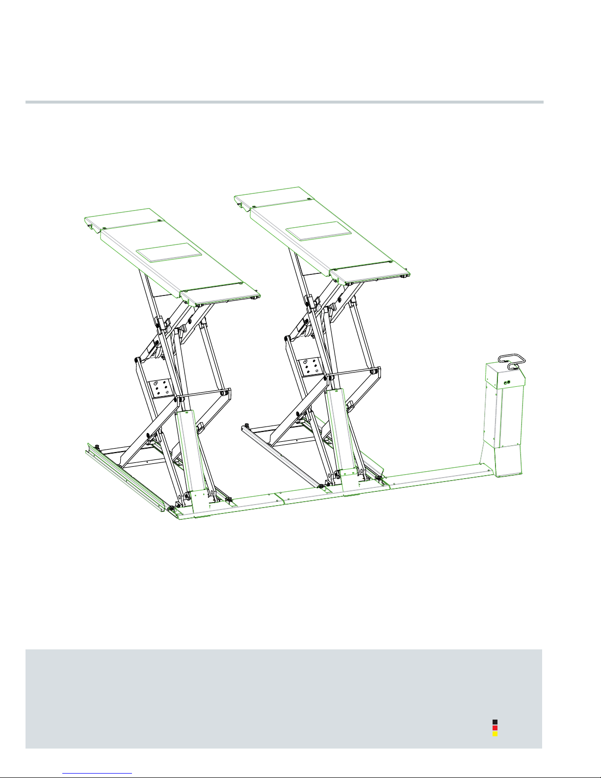
4.2 Setting up the lift
Before setting up the lift, ensure that everything
possible is done to prevent accidents due to care-
less assembly. This includes, above all, the use of
-
Carefully remove the lift from the wooden crate
and check for damage.
Position the lift according to the data sheet at the
desired set up location.
Set up the unit, connect power supply.
iThe set up location of the operating unit can be
selected from two variants. Either in the drive-in
direction at the front right or left.
Fill with hydraulic oil, the manufacturer recom-
mends a high value hydraulic oil with a viscosity of
32 cst. The required oil volume is approx. 14 litres.
12 A1 13 A2
14 N1 15 N2
Move the lifting upwards to approx. 1,500 mm
Check the alignment of the base plates again
to be placed through the holes in the base plates.
Clean the bore holes by blowing them out with
air. Insert safety anchors into the holes.
The manufacturer recommends using approved
safety anchors and to follow anchor manufac-
turer's instructions.
Before anchoring the lift, check whether the con-
-
chor length from the anchor manufacturer's data
the weight bearing concrete, the thickness of this
covering must be determined.
13 12
14 15
11

AD H9402 19.05.2015 JUMBO LIFT 3200 NT - HYMAX XX 3200 PH 55
Align the lift
To prevent hollow spaces, correct any uneven-
and base frame.
Tighten safety anchors with torques recommend-
ed by the manufacturer.
!Each anchor must be tightened to the required
torque. Safe operation of the lift is not guaran-
teed with a lower torque.
Follow the instructions of the anchor manufac-
turer.
Move the lift upwards and downwards several
times, then check the anchors with the torque
wrench and tighten if required. Check the hy-
draulic lines for leak-tightness.
Balance the lift again if required.
Mount all hose covers.
Anchor the foot bumpers included beside the lift
-
sition. Position the foot bumpers and permanently
anchor them Distance between the drive in rails
-
pers may not touch the drive in rails.
Position of the foot bumpers 016
4.3 Fill and vent the hydraulic systems
The lift is factory pre-installed; meaning the hoses
and pipe connections are properly assigned.
Finally, check the power connection, check for
correct hydraulic oil in the proper volume and
leak-tightness of the connection when setting up
the lift.
If the hose connections are still open, e.g. for the
purposes of hose extension, then air may be en-
trapped resulting in start up problems or challeng-
es with smooth running.
Check and ensure proper allocation of hose con-
nections.
!This procedure must always be completely car-
-
perFlow system):
Push the o"Lift" button to move the lift upwards
without a load to the maximum height.
Continue holding the o"Lift" button. This starts the
pump through the command and downstream
cylinders and back into the tank.
After releasing the o"Lift" button, the lift lowers a
The system is now vented and smooth operation
can happen.
The lift now has its normal operating function.
20 mm

56 JUMBO LIFT 3200 NT - HYMAX XX 3200 PH 19.05.2015 AD H9402
4.4 Commissioning
iBefore commissioning, a single safety inspection
must be done (use the "single safety inspection"
form)
trained assembler) then he can also do the safety
inspection. If the set up is done by the operating
company then a specialist must be tasked with the
operation of the lift on the set up protocol for single
safety inspection and releases the lift for use.
iAfter commissioning, the set up protocol must
be completed and sent to the manufacturer.
4.5 Changing the assembly location
To change the assembly location the pre-conditions
must be met according to the assembly guidelines.
The location change is to be done according to
the following sequence.
Move the lifting stage upwards to approx. 1,000
mm
Loosen and remove all hose covers.
Loosen base plate anchors.
Lower the lift to the lowest position.
Disconnect power.
If necessary, disconnect the hydraulic lines on the
operating unit only, and seal them off with blind
stoppers.
If necessary, suction off the hydraulic oil.
Transport the lift with the unit to the new set up
location.
Assemble the lift according to the procedure dur-
-
sioning.
Use new anchors. The old anchors are
iBefore re-commissioning, a safety inspection
must be done by a specialist (use the regular
safety inspection form)
4.6 Selecting the anchors
Anchor type -
ering
(screed/tiles)
(screed/tiles)
BM 10-15/70/40
Liebig/Strongtie FH 15/50 B Anchor length de-
covering
Fischer HSL-3-G M10/40
Hilti
Injection anchor
MKT VMZ-A 75 M12-
25/145
Hilti HIT-HY 200 with HIT-
Z M12
Fischer Highbond FHB II-A S
M12x75/25
iSimilar value anchors and other known brands
of anchor manufacturers can be used when
considering the conditions.

AD H9402 19.05.2015 JUMBO LIFT 3200 NT - HYMAX XX 3200 PH 57
4.7 Assembly
iFollow the instructions enclosed in the anchor
packaging.
011
5 Operating manual
When handling the system, it must ab-
solutely comply with safety regula-
tions. Carefully read the safety regula-
5.1 Operating element
1 Main switch 003
2 o"Lift" button
3 u"Lower" button
4 Model plate
5 Access to the balance screws with locking nuts
6 Access to the emergency discharge screws with locking nut
5.2 Lifting the vehicle
Drive the vehicle over the drive rails lengthwise
and cross-wise in the centre.
When driving onto the lift, position the ramps so
ground.
7 Rollers 004
8 Supports
9 Ramps
damaged.
Secure the vehicle against rolling. Apply the
handbrake, put into gear.
Position polymer overlays below the receiving
points approved by the vehicle manufacturer.
iIf required, use the ramps for safe acceptance
of the vehicle. If the wheel base is too short, fold
the ramps underneath.
To receive the vehicle, the polymer
overlays cannot be placed on edge
otherwise there is a danger of the car
falling.
2 1
5
4
6 3
9
8
7

58 JUMBO LIFT 3200 NT - HYMAX XX 3200 PH 19.05.2015 AD H9402
Inspect the hazardous area.
No person or object may stand in the working
area of the lift, or on the lift.
-
Lift the vehicle. Push the o
If the wheels are not blocked, interrupt the lifting
process and check for proper seating of the poly-
mer overlays.
Raise the vehicle to the desired working height.
Push the o
5.3 Lowering the vehicle
Inspect the hazardous area.
No person or object may stand in the working
area of the lift, or on the lift.
!The vehicles cannot be lowered into the lowest
position without wheels. Otherwise the lift can-
not raise the load using its own force. The ve-
hicle could be damaged.
Lower the vehicle to the desired working height or
completely lower it. Push the u
The entire lowering process must be observed.
If the lift is in the detectable lowest position, re-
move the polymer overlays and drive the vehicle
from the lift.
5.4 Balance the drive rails
-
tem".

AD H9402 19.05.2015 JUMBO LIFT 3200 NT - HYMAX XX 3200 PH 59
6 Maintenance and care of the sys-
tem
Before maintenance, do all prepara-
tion work so there is no danger to life or
limb or object damage during mainte-
nance and repair work.
Value is placed on long lifetimes and safety in the
development and production of Nußbaum prod-
ucts. To guarantee the safety of the operator, prod-
uct reliability, low running costs, keep the warranty
and also the long-lifetime of the product, proper
set up and operation is just as important as regular
the countries we supply to. For example, European
every 12 months of work of the platform. To guaran-
tee the largest possible availability and functional
capacity of the lift system, ensure the list of any
cleaning, care and maintenance work is done.
The lift system is to be serviced at regular intervals
according to the following plan. For intensive oper-
ation and higher degree of contamination shorten
the service interval.
The complete function of the lift system is to be ob-
served during daily use. Customer service must be
informed of any malfunctions or leaks.
To simplify maintenance work, follow instructions on
the maintenance sticker that is found somewhere
on the unit, depending on the lift design.
6.1 System maintenance plan
Before beginning service, disconnect
from power. The system is to be se-
cured against unintentional lowering
and unauthorized access.
6.1.1 As required or visible damage
Check the polymer overlays and replace if re-
quired.
6.1.2 Maintenance 1 x per year
Check condition of the model plate, load capac-
ity and sticker. Exchange them if damaged or il-
legible.
Free the piston rod of the lifting cylinder of sand
and dirt.
Check the wiper for damage.
Moving parts such as joint bolts and DU bearings,
sliding pieces, sliding surfaces and rollers are to
be cleaned and checked for wear, exchange if
required.
Lubricate all lubrication nipples with an acid-free
multi-purpose grease. Do not over-lubricate.
All weld seams must have a visual inspection. Stop
the system and contact the manufacturer if there
are cracks or breaks in weld seams.
Check the powder coating and improve if re-
quired.
immediately after detection. If these points are
cause wide-ranging and permanent damage.
cleaned and degreased. Afterwards, rework with
Check the condition and function of the driving
ramp.

60 JUMBO LIFT 3200 NT - HYMAX XX 3200 PH 19.05.2015 AD H9402
Check the torque of the fastening anchor. Also
see the assembly protocol.
The condition and function of the load suspension
means are to be checked.
Check the torque of the fastening screws.
Fastening class 8.8
0.11* 0.15** 0.20***
M8 20 25 30
M10 40 50 60
M12 69 87 105
M16 170 220 260
M20 340 430 520
M24 590 740 890
Fastening class 10.9
0.11* 0.15** 0.20***
M8 30 37 44
M10 59 73 87
M12 100 125 151
M16 250 315 380
M20 490 615 740
M24 840 1050 1250
* Slide friction number 0.10 for very good surface,
lubricated
** Slide friction number, 0.15 for good surfaces, lubricated
or dry
*** Slide friction number 0.20 surface black or phosphated,
dry
Check electrical components for function. Re-
place any damaged components.
Optional CE stop switch and signalling unit
Push button, main switch
Electrical cable
During assembly and maintenance always check
the condition of electrical lines. All cables and
lines must be secured so they cannot be crushed,
kinked or contact any moving assembly.
Check hydraulic oil.
The oil is used if it has a milky colour or if the hy-
draulic oil smells unpleasantly.
Check the hydraulic lines and screws for leaks.
Hose lines are to be replaced:
for damage to the outer coating up to the in-
-
mation), deformation of the natural shape in
the depressurized and in pressurized states.
if leaking
-
ture
if the lifetime has been exceeded
Repair of the hose line using the implemented
Extending the replacement intervals given in the
guideline is possible if the inspection for safe-work
condition is done in adjusted, shortened time
frames, if required and by competent personnel.
If ther is an extension of the replacement interval,
no situation may occur which could result in injury
of employees or other personnel.
Check the condition and function of all available
safety devices.
Check the foot bumper for condition and func-
tion. Exchange if damaged

AD H9402 19.05.2015 JUMBO LIFT 3200 NT - HYMAX XX 3200 PH 61
6.1.3 Maintenance every 2 years
According to manufacturer details, the hydraulic
oil should be changed every two years in normal
location, temperature swings, intensive opera-
the hydraulic oil. For this reason, the oil must be
checked during annual safety inspections and
maintenance.
The oil is used if it has a milky colour or if the hy-
draulic oil smells unpleasantly.
To change oil, lower the lift is to its lowest position
then suction the oil out of the oil container and
replace the contents.
The manufacturer recommends a high-quality
clean hydraulic oil. The required oil volume and
type is to be taken from the technical data. After
-
per and lower marking on the oil dipstick, or ap-
Dispose of the old oil according to regulations
-
-
disposal points).
6.1.4 Maintenance every 6 years
Exchange the protective and hydraulic hoses.
Excerpt from BGR 237
6 years including 2 years storage time.
Increased demands e.g. due to increased us-
age times, e.g. multi-shift operation, short cycle
times and pressure impulses and large external
2 year operation duration
6.2 Cleaning and care of the system
A regular and expert clean helps retain the value
of the system.
Additionally, it can also be a pre-requisiste for the
preservation of guarantee claims for any eventual
corrosion damage.
The best protection for the system is regular remov-
al of contaminants of any kind.
This includes above all:
de-icing salt
sand, pebbles, earth
industrial dust of all types
Water, also in connection with other environmen-
Aggressive deposits of all types
!As a rule: The longer road dust, salt, and other
aggressive deposits remain caked onto the sys-
tem, the more damage they will have.
The frequency of system cleaning depends, among
other things on the frequency of use, of system han-
dling, of workshop cleanliness, and the location of
the system.
Furthermore, the degree of contamination de-
pends on the time of year, the weather conditions
and workshop ventilation.
Under adverse circumstances, weekly system
cleaning might be required, however a monthly
For cleaning, do not use high pressure washers
Do not use any aggressive and abrasive materi-
als. Instead, use mild cleaners, e.g. a commer-
cially available detergent and lukewarm water.
Carefully remove all contamination with a
sponge, or if required with a brush.
Make sure that there is no residue of the cleaner
on the system. These could lead to an increased
danger of slipping when moisture is present. So
rinse thoroughly with clean water until all residue
has been removed.
Be sure that electric parts of the system, cables,
hoses, etc. do not come into contact with water.

62 JUMBO LIFT 3200 NT - HYMAX XX 3200 PH 19.05.2015 AD H9402
Dry the system with a cloth and spray it with a
spray wax or oil.
iTo encourage/accelerate the airing and/or
drying of foundation pits and lift parts, when-
a longer period of time, including overnight, lift
them out of the foundation pit.

AD H9402 19.05.2015 JUMBO LIFT 3200 NT - HYMAX XX 3200 PH 63
7 Behavior in cases of error
Defective operational readiness of the system may be due to a simple error. Check the system for the listed
sources of error.
If the error cannot be removed after an inspection to the named causes, then inform customer service or
your dealer.
Independent repair work on safety devices of the lift and checking the electrical system
may only be done by specialists.
Problem: Motor does not start
Possible causes: Remedy:
No power supply Check the power supply
Defective fuse Have fuses checked
The o Inform customer service
Motor has overheated Let the water cool.
Cooling time depends on the ambient temperature.
Motor defective Inform customer service
Problem: Motor starts, load is not lifted
Possible causes: Remedy:
Load is too heavy Unload the lift
Pressure line leaking Inform customer service
Hydraulic pump defective Inform customer service
The coupling between the motor and pump is
defective Inform customer service
Defective cylinder Inform customer service
Pressure relief valve is defective Inform customer service
Problem: The lift cannot be lowered
Possible causes: Remedy:
Lifting table is sitting on an obstacle See 7.1 Moving onto an obstacle
Hydraulic valve defective Inform customer service
The o Inform customer service

64 JUMBO LIFT 3200 NT - HYMAX XX 3200 PH 19.05.2015 AD H9402
7.1 Moving onto an obstacle
If the system moves onto an obstacle during lower-
ing, then it remains in position due to the mechani-
cal resistance. In this case, move the lift upwards
by pushing the o
panel until the obstacle can be removed. After-
wards the lift is in a normal work condition and can
continue to be operated as described in the oper-
ating manual.
7.2 Emergency discharge during blackout
An emergency discharge is an access
into the system controls and may only
be done by experienced specialists.
The emergency discharge must be
done in the following described se-
quence, otherwise it can lead to dam-
age and hazard to life and limb,
Any kind of external leakage is not
permitted and must immediately tak-
en care of. This is absolutely necessary
especially before an emergency dis-
charge.
Reason which make an emergency discharge nec-
essary are for example, electrical blackout, for er-
rors in the lowering valves, etc.
1 Main switch 003
5 Access to the balance screws with locking nuts
6 Access to the emergency discharge screws with locking nut
unauthorized switch on. Disconnect power.
!Inspect the hazardous area. No person or ob-
ject may stand in the working area of the lift, or
on the lift.
Remove the covers for the emergency discharge
-
the emergency screw N1 by 1/4 turn.
!Caution: During this process a drive on rail of the
lift will lower somewhat (approx. 5 cm). Lower-
ing can be interrupted by closing the emergen-
cy discharge screw.
Subsequently unscrew the opposite emergency
discharge screw slowly a little.
!The lowering process starts immediately. The
emergency discharge screw is opened.
Lower the lift to the lowest position.
The entire lowering process must be continuously
observed.
Afterwards, remove the polymer overlays and
drive the vehicle from the lift.
and lock the emergency discharge screws N1
and N2 again.
before the lift is put into operation again. For this,
inform customer service.
Turn the main switch off and secure
against restart. Shutdown the lift un-
til all defective parts have been ex-
changed.
!After exchange of defective parts a "Vent of the
hydraulic system" must be done.
1
5
6

AD H9402 19.05.2015 JUMBO LIFT 3200 NT - HYMAX XX 3200 PH 65
8 Technical information
8.1 Technical data
Weight 920 kg
System load capacity 3,200 kg
Load distribution Max. 3:2 or 2:3 in or
against the drive- in direction
Effective lifting range
of the system Approx. 2,000 mm
System lift time Approx. 35 s with 3,200 kg load
System lowering
time Approx. 30 s with 3,200 kg load
Operating pressure Approx. 270 bars
Operating voltage 3 x 400 Volt , 50 Hz
Motor capacity 3 kW
Motor speed 3000 rpm
Oil pump conveying power 3 cm³
Pressure relief valve Approx. 300 bars
Filling volume oil container Approx. 14 litres
with 16 A fuses,
slow, according to
VDE regulations
8.2 Safety devices
Over-pressure valve
Hydraulic system fuse against over-pressure.
Check valve
Secure the vehicle against unauthorized lowering
of the load suspension means
Two independent cylinder systems (each with a
command, follow system)
Secure against unauthorized lowering of the lift.
Main switch with locking device
Fuse to prevent unauthorized use.
Dead man controls
When the buttons ou
released, the corresponding movement stops
Foot bumper on the lift (optional)
Guard against crushing in the foot area.
CE stop (optional)
Guard against crushing in the foot area.

66 JUMBO LIFT 3200 NT - HYMAX XX 3200 PH 19.05.2015 AD H9402
9 System master sheet
9.1 Manufacturer
Otto Nußbaum GmbH & Co.KG
Korker Straße 24
D-77694 Kehl-Bodersweier
9.2 Purpose
The JUMBO LIFT 3200 NT - HYMAX 3200 PH lift is a lift for cars up to a total weight of 3,200 kg in normal work
shop operations and a maximum load distribution of 3:2 or 2:3 in the drive-in direction or against the drive-
in direction.
Additionally, there is a distinction between cars operated with front or rear drive.
-
lift must be inspected afterwards by a specialist who approves the changes.
Operation of the lift is done by an operating unit that is located immediately next to the lift.
9.3 Changes to the design / construction
expert signature).
........................................................................................................................................................................................
........................................................................................................................................................................................
Name, address of technical expert
...................................................................................... ............................................................................................
Location, date Technical expert signature
9.4 Changing the assembly location
signature).
........................................................................................................................................................................................
........................................................................................................................................................................................
Name, address of technical expert
...................................................................................... ............................................................................................
Location, date Technical expert signature
This manual suits for next models
1
Table of contents
Other Nussbaum Scissor Lift manuals
Popular Scissor Lift manuals by other brands

Skyjack
Skyjack Compact Rough Terrain Series Maintenance and parts manual

Bishamon
Bishamon BX30B Operation and service manual

SICE
SICE PSR 43 CT LT instruction manual

Genie
Genie GS-4655 Operator's manual

Snap-on Equipment
Snap-on Equipment EELR591A Installation and operating manual

Stratus
Stratus SAE-UT12000 Installation, operation & maintenance instructions

Bend-Pak
Bend-Pak LR-10000 Service manual

Genie
Genie 360 GS Series Tech tips

Vestil
Vestil DGS-A-PSD instruction manual

twin busch
twin busch TW SA 42 U V2 Installation, operation and maintanance manual

Tuxedo
Tuxedo MR6K-48 Assembly & operation manual

TIGIEFFE
TIGIEFFE Airo X Series Use and maintenance manual