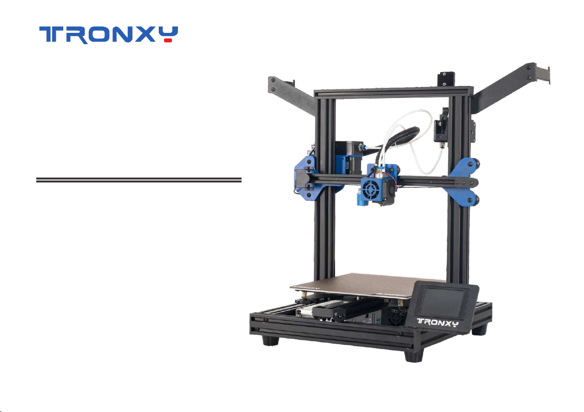
TRONXY XY-2 PRO User manual
InstallationManualXY-2PRO2E

UsernoticePleaseusethemachineinaventilated,dry,cleanandflatenvironment.Whenunpacking,pleasecheckthepackinglisttoensurethatthereisnolossordamageofparts.Ifany,pleasecontactourafter-salespersonnelimmediately,andwewillsentreplacementforyouintheshortesttime.SomeaccessoriesareFilamentwithdifferentwarrantytime.Incaseofemergency,thepowercanbeturnedoffdirectly.Thismachinecontainshigh-speedmovingpartsandhigh-temperatureparts.Childrenarenotallowedtousethismachinealone.Iftheusermodifiesordisassemblesthecorecomponentsofthemachinewithoutauthorization,thissituationisnotcoveredbythewarranty.Video,softwareandotherrelatedinformationarestoredinTFcard.

1.Machinedetails2.Machineparameters3.Packinglist4.Machineinstallation5.Machinestructureinspectionandadjustment6.Powersupplyvoltageinspectionandadjustmentmethod7.Buildplatformleveling-autolevelingdetection8.Buildplatformleveling-manualleveling9.Loadingandremovingfilaments10.Printtest11.Settingofslicingsoftware12.Howtouseslicesoftware13.Failurecauseanalysis01020304212223262731334043Directory
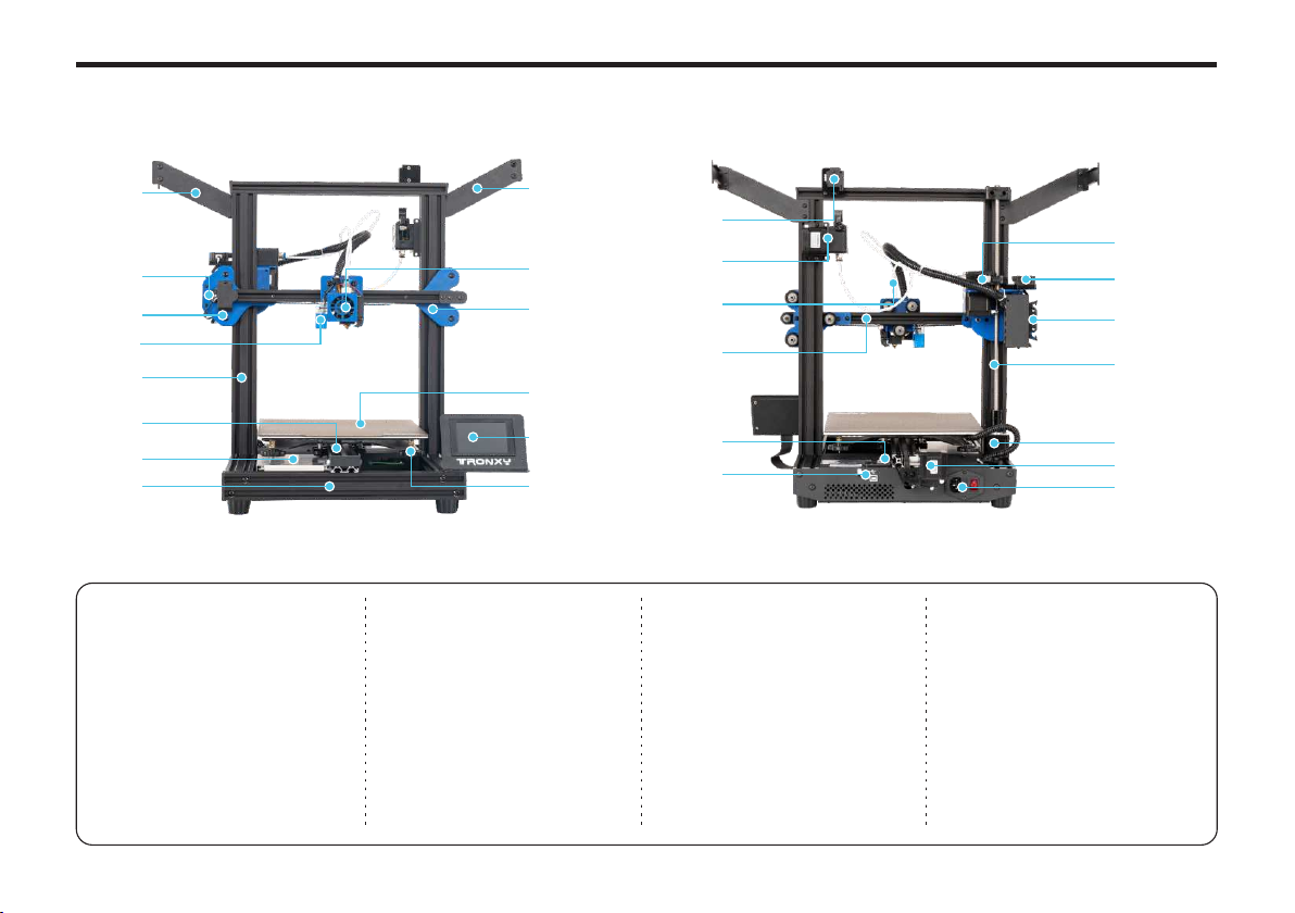
Machinedetails20011916152122232425262709101112131408070605040301171801020304050607LeftfilamentrackX-axismotorassemblyZ-axisleftsliderAutolevelingdetectorGantryY-axisaluminumprofilePowersupply08091011121314BasealuminumprofileRightfilamentrackPrintheadcomponentZ-axisrightsliderPrintingPlatformTouchscreenLargelevelingnut15161718192021E2filamentrun-outdetectorE2extruderFilamenttubeX-axisaluminumprofileY-axislimitswitchTFcardandtype-BtoUSBslotE1 extruder222324252627E1filamentrun-outdetector30PincablesocketScrewrodZ-axismotorY-axismotor02Powercordsocketandpowerswitch

PrintparametersTemperatureparametersPowerparametersSoftwareRelatedMachineParametersMachine weight≈12kgPacking size510*480*230mmMachine size478*455*520mmConnection method
TFcard,Type-B,Thumbdrivesocket
Output Format.gcodeInput Format.stl、.objSlicing softwareTronxy、Cura、Simplify3DAC110/220V50/60HzDC24V/360WAvailable filamentsPLA、ABS、PETG、···PositionaccuracyX/Y-0.00625mm,Z-0.00125mmPrintspeed20-100mm/s(60mm/sispreferred)Nozzlequantity1Nozzlesize0.4mmPrintingprincipleFDM(Fuseddepositionmolding)Printaccuracy0.1-0.3mmPrintsize255*255*260(mm)8-40℃Printing environment temperature275℃(Max)Nozzle temperatureMachineparameters02

0318191314151617891011123456712BaseGantryM5*45screw*4Filamentrack*2E2extruderE2filamentrun-outdetectorFilamenttubePEImagneticsteelplate0.25KGFilaments(Randomcolor)PowercordShovelknifeCardreaderandTFcardHexagonwrenchType-BtoUSBCableScrewdriverTie(Randomcolor)WrenchLimitswitch(sparepart)L-shapedhexagonalwrenchPackinglist

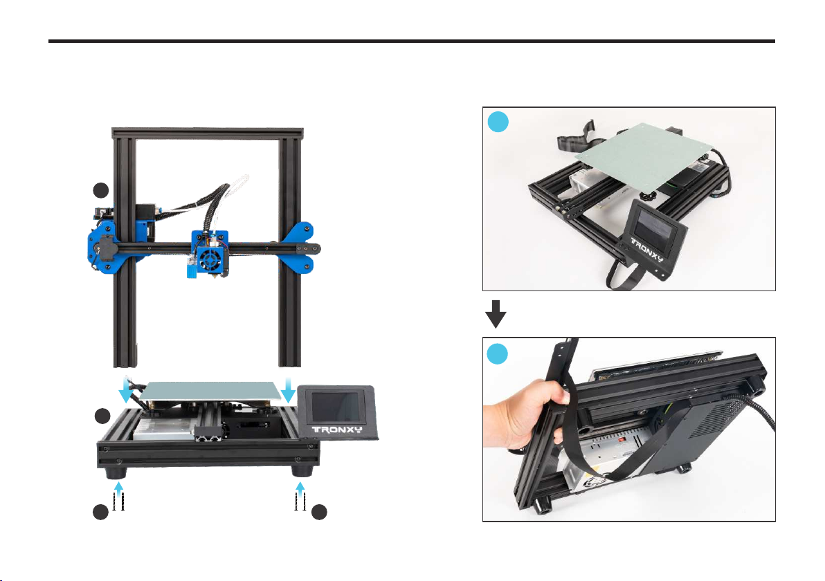
1.Removethetouchscreenonthebase04LoosenthescrewhereLoosenthescrewhereRemovethetouchscreen1Base14Hexagonwrench123Machineinstallation

052.Asshowninthefollowingfigure,adjustthescrewsandboatnutspre-installedonthetouchscreen1234RemovescrewsandboatnutsInstallitbackasshowninthefigureInstallationcompletiondiagramThetouchscreenjusttakenoffMachineinstallation
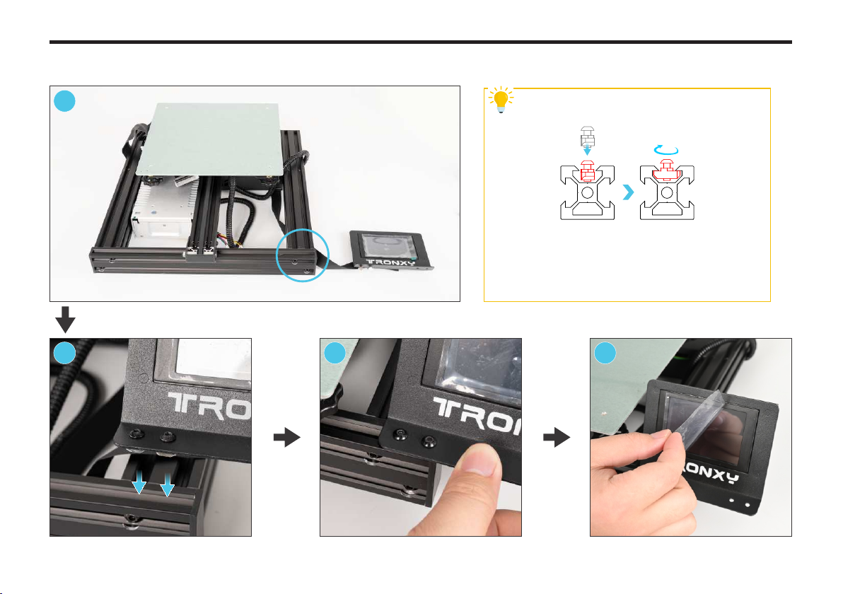
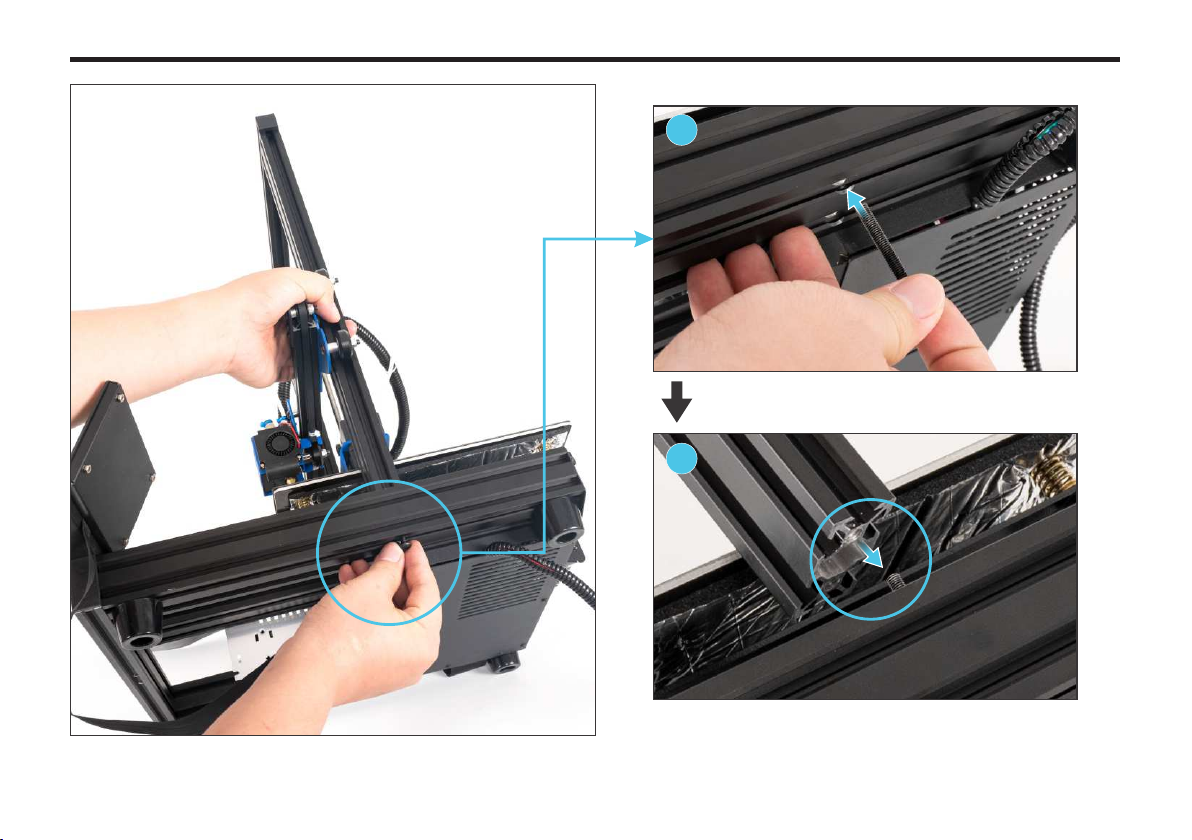
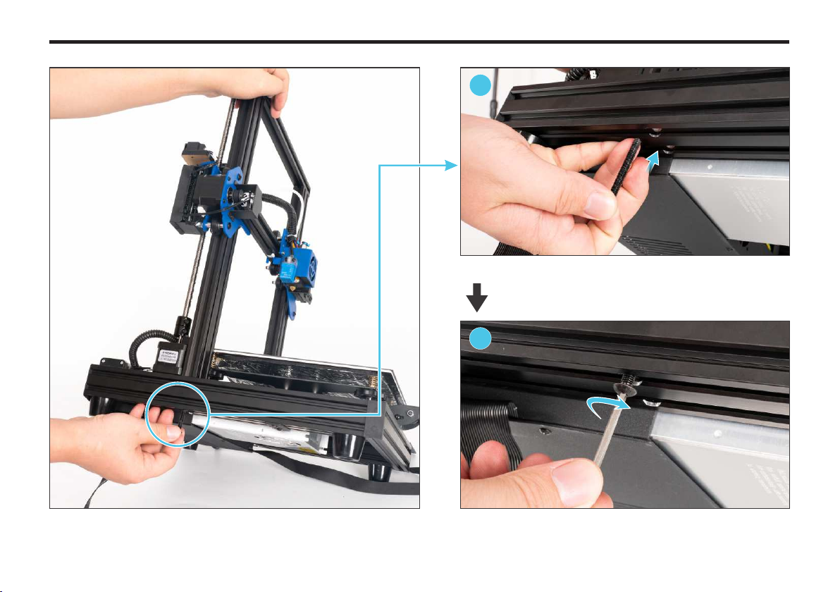
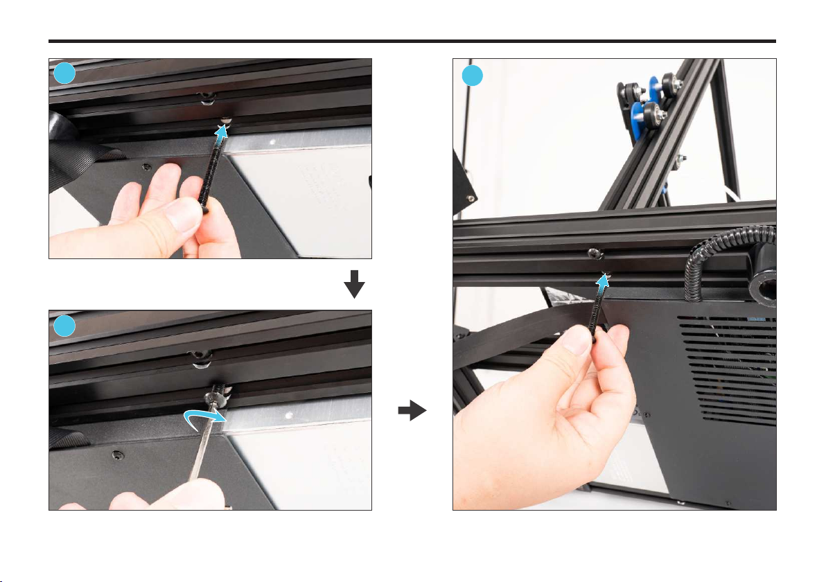
063.CorrectlyinstallthetouchscreenonthebaseWorkingPrincipleofboatnutLoosentheboatnutonthefilamentrackslightly,payattentionnottotakedownthenut,thenputitintothegrooveofaluminumprofileinparalleldirection,andtightenthescrewclockwisequickly,makingtheboatnutstuckinthegrooveofaluminumprofileat90°.
Tips
1234InstallthetouchscreenintheplaceofcircleinthefigurePuttheboatnutintothegrooveTightenscrewsTearoffthescreenprotectivefilmMachineinstallation
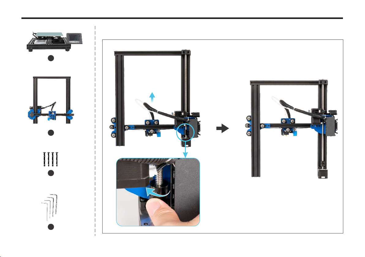
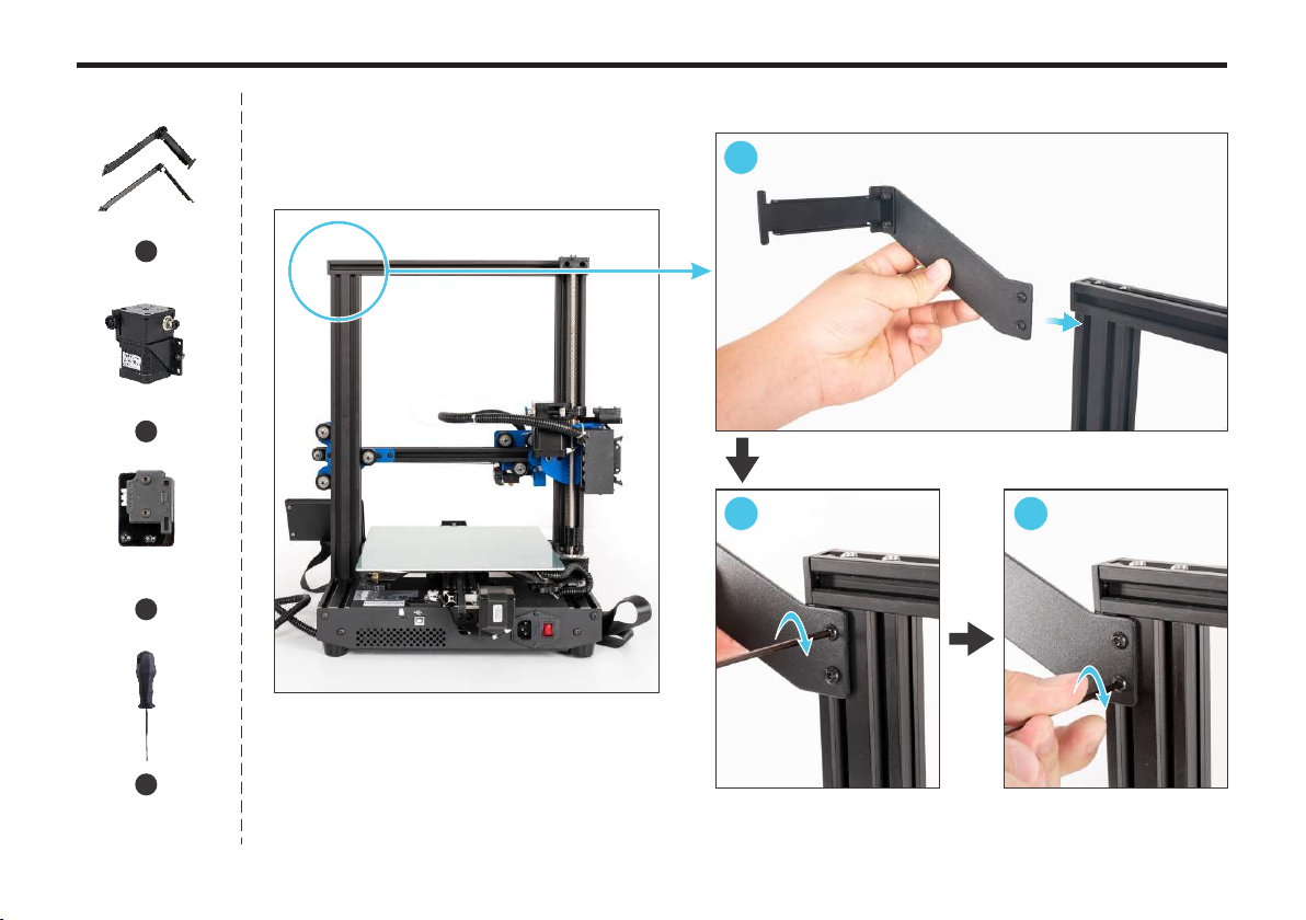
074.Rotatethescrewcouplingclockwisetoraisethexaxisabovethemiddle2Gantry1Base3M5*45screw*417L-shapedhexagonalwrenchGantrybackMachineinstallation
08Installationdiagram3321Procedure5.Installthegantrytothebase12LifttherightsideofthebasetoshowthebottomMachineinstallation
0934InserttheM5*45screwintothescrewholeInsertthescrewholeatthebottomofthegantrywiththescrew,andscrewthescrewintoalittlebitMachineinstallation
10InserttheM5*45screwintothescrewholeUseanL-typewrenchtotightenthescrewclockwise56NowcometothebottomontheleftofthemachineMachineinstallation
InserttheM5*45screwintothescrewholenexttoitUseanL-typewrenchtotightenthescrewclockwiseBacktothebottomontherightandinserttheM5*45screwintothescrewholenexttoit78911Machineinstallation
UseanL-typewrenchtotightenthescrewclockwiseFinally,tightenthescrewinstalledatthebeginning10111212FrameworkinstallationcompletedMachineinstallation
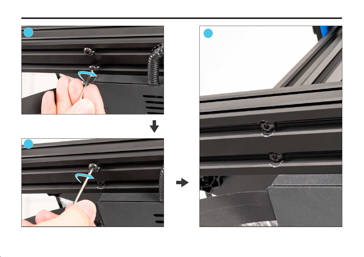
6.Installfilamentrack,E2extruderandE2filamentrun-outdetector123InstallrightfilamentrackUseahexagonalwrenchtotightenthetwoscrewsclockwise4Filamentrack*2E2extruderE2filamentrun-outdetector561413MachineinstallationHexagonwrench

UseahexagonalwrenchtotightenthetwoscrewsclockwiseInstallleftfilamentrack14Machineinstallation456Installinthepositionshowninthepicture

Useahexagonalwrenchtotightenthetwoscrewsclockwise8915MachineinstallationInstalltheE2extruder7Installinthepositionshowninthepicture
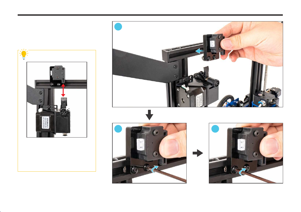
Thefilamentrun-outdetectorisinstalledrightabovetheextruder,andthefeedingholeofthedetectorisverticallyalignedwiththefeedingholeoftheextruder.InstallE2filamentrun-outdetectorUseahexagonalwrenchtotightenthetwoscrewsclockwise10111216MachineinstallationTips
Other manuals for XY-2 PRO
2
Table of contents
Popular Cutter manuals by other brands


Classen
Classen SCHV-12/5.5 Operator's manual

Klauke
Klauke SDG85/2 instruction manual

wurth
wurth MSF 180 N Translation of the original operating instructions

Clarke
Clarke X-Pro CAT203 Operating & maintenance instructions

Kapriol
Kapriol Sirmex SC Plus Series Instruction handbook

Lincoln Electric
Lincoln Electric Torchmate 5100 Series quick start guide


