HE.13520_C © 02/2011
Bedienungsanleitung Schneidkopf
3
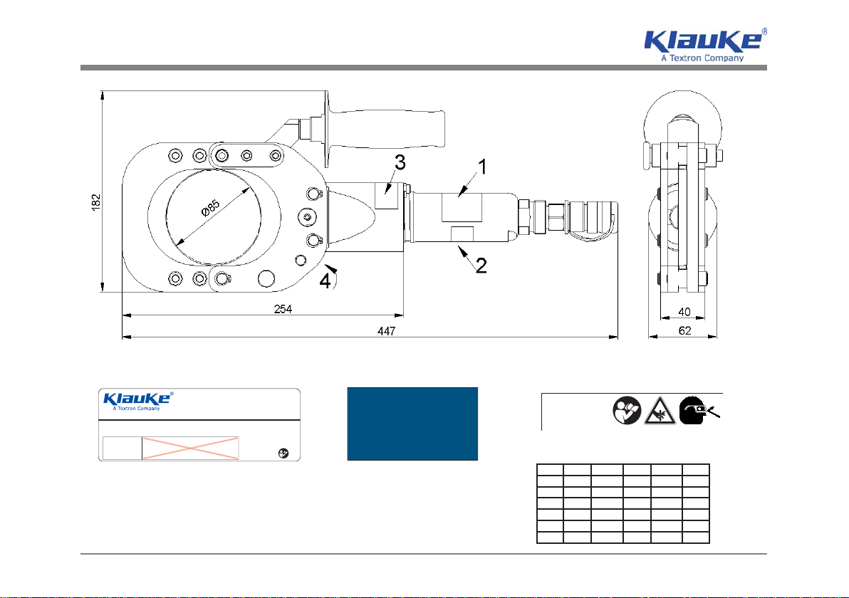
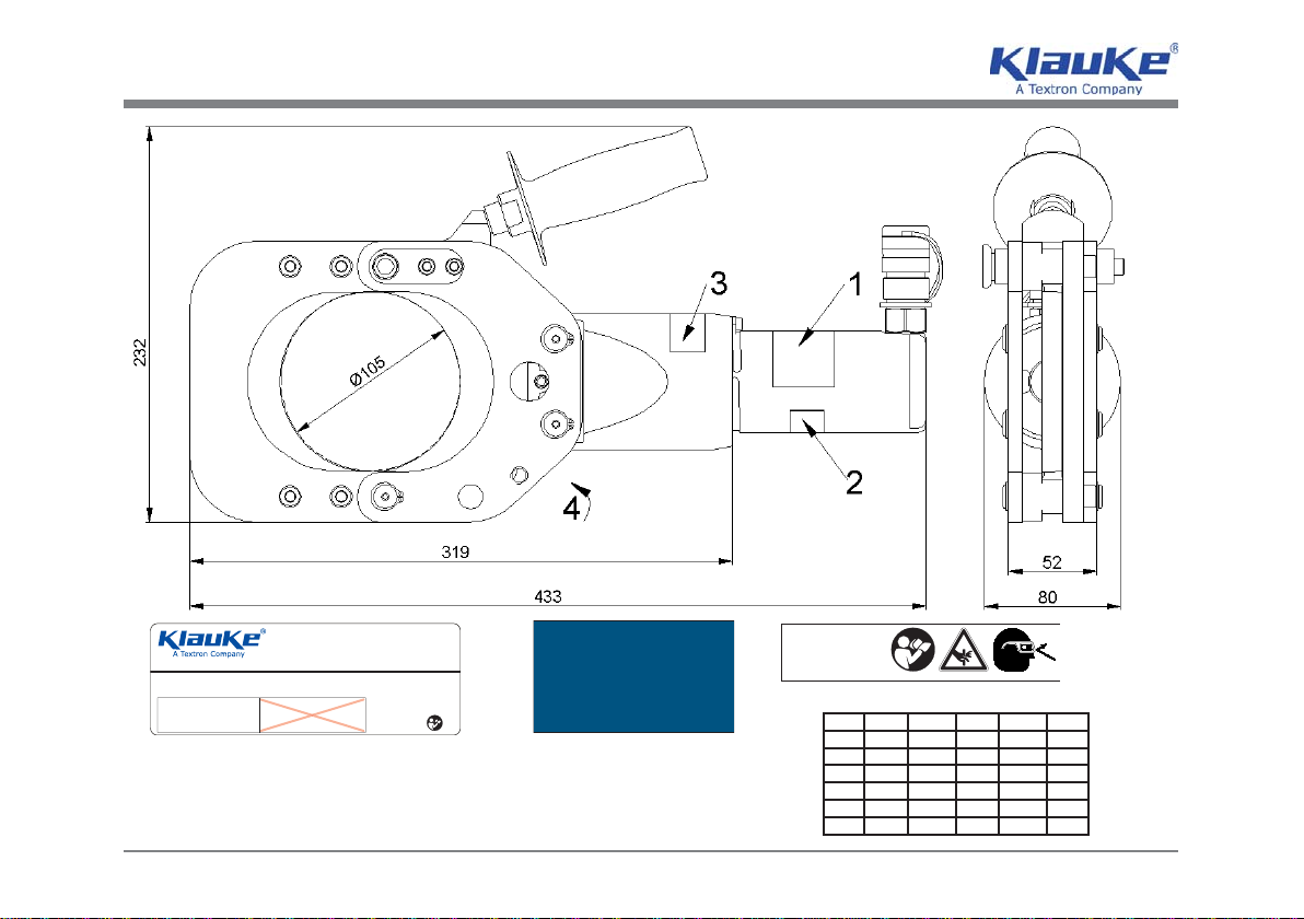
SDG85/2 SDG85/2C SDG105 SDG105C
D
original
bed.anl.
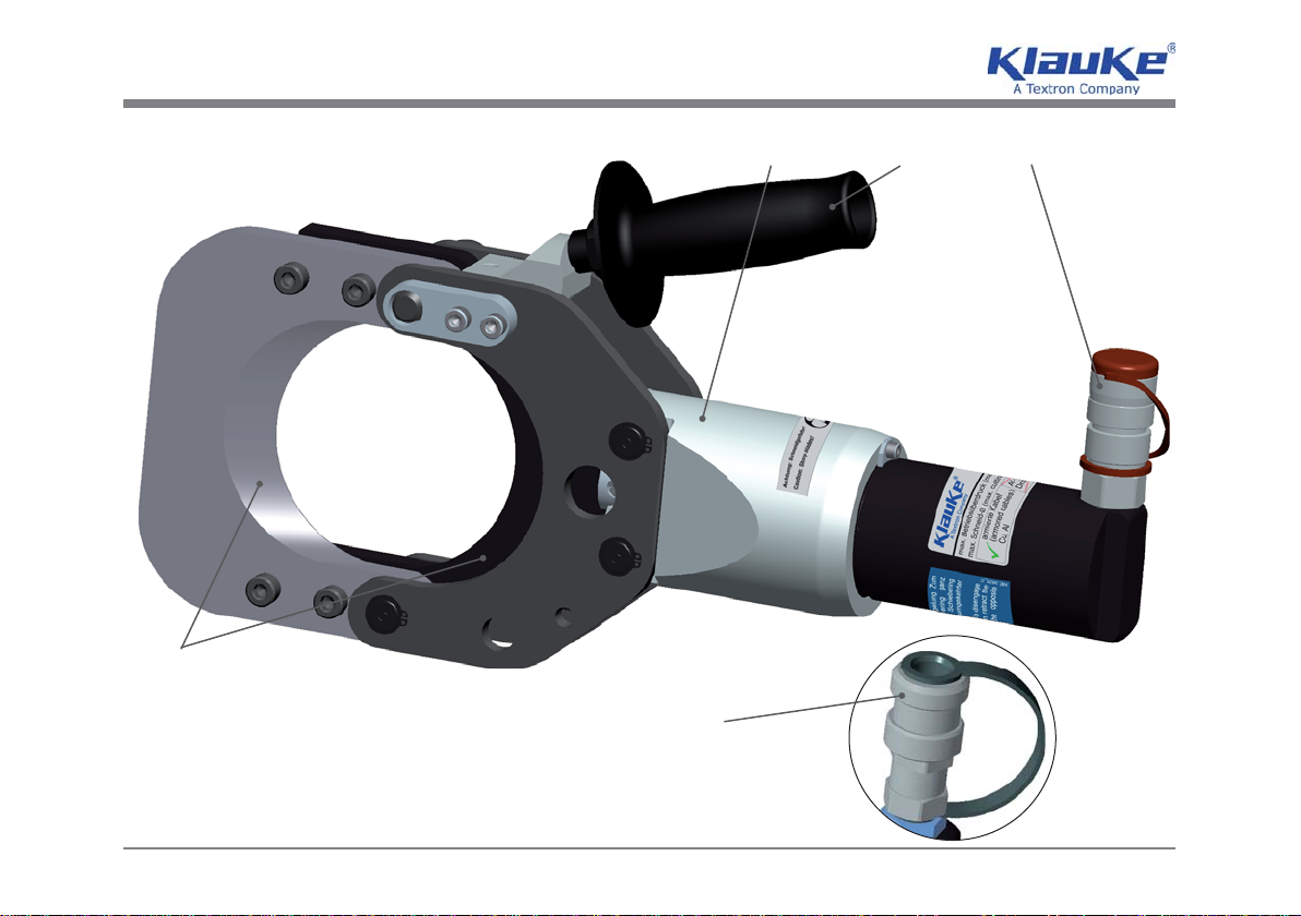
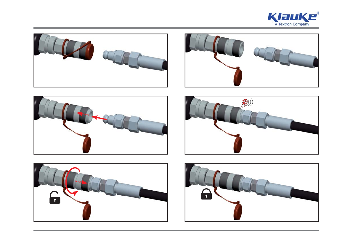
1.Anschluß des Schneidkopfes (Bild 1.2) über die Schnellkupplung (Bild 1.4) an eine Fuß-/Elektropumpe und voll-
ständiges Ausrollen des Hochdruckschlauches.
2.Ablauf siehe Bilder 11-14.
3.Positionieren Sie den Schneidkopf so, daß er im rechten Winkel zum zu trennenden Kabel liegt. Der Schneidkopf
muß so an das Kabel angelegt werden, daß sich seine Lage während der gesamten Schneiddauer nicht ändert.
4.Das auf dem Kolben sitzende bewegliche Schneidmesser fährt auf das Kabel zu. Der Schneidvorgang ist beendet,
wenn sich die beiden Schneidmesser (Bild 1.1) vollständig überdecken.
5.Nach vollständiger Trennung des Kabels wird der Rückstellhebel an der Fußpumpe betätigt und die Schneidmes-
ser (Bild 1.1) werden in ihre Ausgangslage zurückgefahren.
Achtung
Tragen Sie geeignete Kleidung. Tragen Sie kleine weite Kleidung oder Schmuck.
Achtung
Sorgen Sie für einen sicheren Stand und halten Sie jederzeit das Gleichgewicht.
Achtung
Tragen Sie persönliche Schutzausrüstung und immer eine Schutzbrille.
4.2. Anwendungsbereich
Mit unserem hydraulischen Kabelschneider können alle bekannten nicht und leicht armierten Kabel bis zu
einem maximalen Außendurchmesser von 85 mm/ 105 mm geschnitten werden.
Achtung
Das Schneiden von Kabeln mit Stahlarmierung führt zu Beschädigungen der Schneidmesser.
Vor Arbeitsbeginn ist ein spannungsfreier Zustand des zu schneidenden Kabels sicherzustellen.
Achtung
Es dürfen keine unter Spannung stehenden Teile geschnitten werden.
Um den unterschiedlichen Einsatzbereichen des Schneidkopfes rechnung zu tragen, stehen unterschiedliche
Schlauchlängen von 3, 4, 5, 6, 8 und 10 m zur Verfügung.
armoured