DMC Twist-Strip User manual

©COPYRIGHT 2018 DANIELS MANUFACTURING CORPORATION WWW.DMCTOOLS.COM (407) 855-6161 PATENT #7,243,429
TSK8000 MANUAL TSK8000-M REV E

©COPYRIGHT 2018 DANIELS MANUFACTURING CORPORATION WWW.DMCTOOLS.COM (407) 855-6161 PATENT #7,243,429
TSK8000 MANUAL TSK8000-M REV E
IMPORTANT
WWW.DMCTOOLS.COM
Phone: (407) 855-6161
Fax: (407) 855-6884
Important Note from Manufacturer:
Prior to the use of this tool, the operator should
take a sample of the wire they will be using and test the viability of the strip. Adjustments
may be needed for desired outcome that vary from the factory recommendation.
!
Important Note from Manufacturer: Different suppliers and/or production runs
of cable can vary in key strip dimensions and properties. Inspect frequently and
readjust blade depth if necessary.
!
Important Note from Manufacturer: Care should be taken when handling
insulation or shielding as nicked, frayed, or broken strands can cause injury.
!
We are committed to Daniels Manufacturing Corporation (DMC) remaining the major
supplier of high reliability tools and maintenance kits for electronic wiring systems to the
global aerospace, military, transportation, electrical, and electronic industries through our
continuous improvement of all our business practices and processes while, at the same
time, maintaining the economic viability of our business.
- George Daniels, President
To meet this commitment, Daniels Manufacturing Corporation maintains an ISO9001/AS9100
Registered Quality Management System.

©COPYRIGHT 2018 DANIELS MANUFACTURING CORPORATION WWW.DMCTOOLS.COM (407) 855-6161 PATENT #7,243,429
TSK8000 MANUAL TSK8000-M REV E
1.0 Introduction ................................................. 1
1.1 Overview of Existing Practices..................... 1
1.2 Product Overview ......................................... 2
1.3 Cable Variances............................................ 2
2.0 Tool Features............................................... 3
2.1 TS8000 Key Features ................................... 3
2.2 Interchangeable Dies .................................... 3
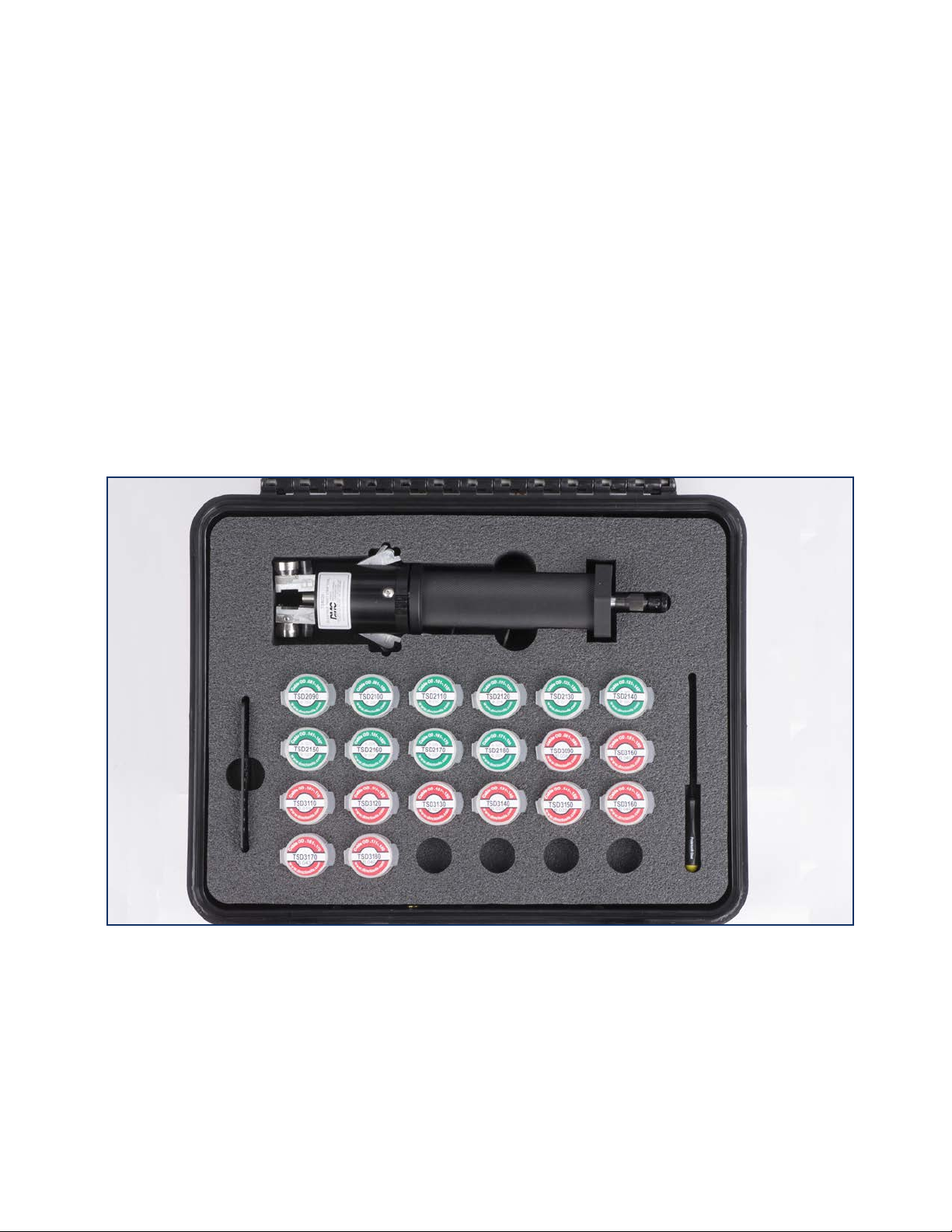
3.0 Die and Die Container Information ........... 4
3.1 Denitions ..................................................... 4
3.2 Die Set Identification .................................... 4
3.3 Die Set Part Numbering System .................. 5
3.4 Die Set Selection Notes................................ 6
3.5 Cable Diameter Gauge Card ........................ 6
4.0 Tool Anatomy .............................................. 8
5.0 TS8000 Operation Overview.......................9
5.1 Opening and Closing.................................... 9
5.2 Installing Dies.............................................. 10
5.3 Release Arms to Operate Tool.................... 11
5.4 Setting Cable Strip Length ......................... 12
5.5 Inserting Cable............................................ 13
5.6 Stripping the Cable..................................... 14
5.7 Crack and Peel the Jacket ......................... 15
5.8 Damage or Improper Strip.......................... 16
6.0 Depth Control Knobs................................ 17
6.1 Adjusting Blade Depth................................ 18
7.0 TS8000 Testing Procedures ..................... 19
7.1 TS8000 Strip Test Procedures.................... 18
7.2 Accuracy of Strip Test ................................ 18
8.0 Quality Check When Inserting Dies ........ 18
9.0 TS8000 Specifications .............................. 19
9.1 ToolSpecications...................................... 20
9.2 Cable Specifications................................... 20
9.3 Other Cable Specifications......................... 20
10.0 NEMA WC 27500 Shielded and Unshielded
Cable Part Numbering System................ 21
11.0 Jacket Material ......................................... 22
12.0 Troubleshooting ........................................ 23
12.1 Tool Arms Will Not Open ............................ 23
12.2 Arms Will Not Stay Closed With Die Set
Installed ...................................................... 23
12.3 Arms Will Not Stay Closed with a
Die Set NOT Installed ................................. 23
12.4 One Side of the Die Set is Cutting
too Deeply/Shallow..................................... 23
13.0 Maintenance, Precautions,
Service & Repair........................................ 23
14.0 Contact Info for DMC Recalibration
and Repair ................................................. 24
15.0 Custom Dies.............................................. 24
16.0 Warranty Statement.................................. 24
Patent, Trademark, and Copyright Information
The configuration and general design of the TS8000
Twist-StripTM tool and related dies follows the content
of US Patent #7,243,429.
Twist-StripTM, DMC, and Daniels Manufacturing Corp.
are registered Trademarks and Logos of the Daniels
Manufacturing Corporation, Orlando, Florida (USA).
This manual and other publications relating to Twist-
StripTM Tooling are copyrighted by Daniels Manufacturing
Corp., and shall not be used or duplicated without
express written permission of DMC.

TSK8000-M REV E TSK8000 MANUAL
©COPYRIGHT 2018 DANIELS MANUFACTURING CORPORATION WWW.DMCTOOLS.COM (407) 855-6161 PATENT #7,243,429
11
INTRODUCTION:
It is common for high-speed data cable to utilize one or more shielded twisted conductors.
This type of cable is common in all digital electronic networks, and it requires new tooling
disciplines.
The TS8000 Twist-StripTM tool is a cable jacket stripper designed to slit the jacket on
multi-conductor shielded twisted cable. Safe, accurate and repeatable, the Twist-StripTM
makes quick work of avionics harnesses and many other cable types, cutting preparation
time by up to 3 - 5+ times. The challenge in designing a wire prep system of this type is the
non-circularcongurationofthecable,andthemanytypes,variations,andstrippingnuances
of shielded, twisted, multi-wire cable. DMC’s intention of the Twist-StripTM product line is to
give the user a system with the maximum capabilities, while keeping the system portable,
self-contained, affordable, and ergonomic. The precise blade adjustment, zero friction roller
bearing design, articulating/locking arms, and changeable dies make the Twist-StripTM very
user-friendlyandefcientwhenperformingthedifculttaskofcablepreparation.
Overview of Existing Practices:
Removing the jacket from multi-conductor cable is often done by hand with a razor blade.
Thisisadangerousanddifcultwaytoremovethejacketfromanytypeofelectricalcable.A
razor blade offers no method of controlling the depth of cut. This will result in a poor quality
strip, damage to the shielding, and the probability of injury to the operator.
Tools which score a ring around the outer jacket, but don’t slit the jacket horizontally leave
the operator with the task of removing a long jacket segment by force. This causes operator
fatigue, and the friction caused by pulling wire slugs across the cable can open large windows
in the braided shielding, therefore making the shielding less effective.
A few benchtop strippers are available for oval cable, but none are portable, and all are
expensive. One very popular benchtop stripper for oval wire weighs 24 pounds, and still
requires the operator to pull the insulation slug off the cable.
Laser stripping is another precise method for wire stripping, however it is expensive and has
multiple hazards. Laser stripping emits toxic fumes when burning the outer jacket and can
be a potential exposure to radiation. The laser stripping process requires a tight braid layer to
stop the laser energy. It can penetrate below openings in the woven wire braid and burn holes
in the insulation of the inner conductors. When this occurs, solder can reach the inner
conductors and cause electrical shorting to ground.
1.0
1.1

©COPYRIGHT 2018 DANIELS MANUFACTURING CORPORATION WWW.DMCTOOLS.COM (407) 855-6161 PATENT #7,243,429 2
TSK8000 MANUAL TSK8000-M REV E
1.2
1.3
Product Overview:
The patented TS8000 Twist-StripTM tool utilizes custom-made die sets and precise adjustable
cutting blades. The adjustable blades allow the tool to compensate for minor thickness
variancesinthecablejacketandlaylengthwithsignicantlylessdowntime.Anengineered
cabletrackinthediesiscontouredtomatchtheouterjacketproleofthecablebeing
stripped. This feature provides controlled rotation of the dies to guide the cutting blades in
a precise track along the length of the cable. The Twist-StripTM is the best way to remove the
outer jacket from twisted, shielded multi-conductor cable. The TS8000 eliminates the need
for imprecise and dangerous razor blades. The TS8000 die sets can accommodate an outer
diameter range of cables from .071” to .180”.
Cable Variances
Multi conductor shielded twisted cables can have variations despite being supplied by the
same manufacturer; with the same lot code, date code, and/or part number. Varying jacket
thickness and cable diameter are two examples of common differences that may seen in
different lots of the same cable.
Since the cable standards are based on the performance of the cable rather than dimensional
conformance, it has been our observation that outside dimensions have varied by as much as
.030”, twist pitch (lay) can vary by as much as 40%, and jacket thickness has been observed
to vary by as much as .007”. The variations are often increased when the cables are produced
in different lots, or by different manufacturers, and supplied under the same part numbers.
By selecting a matched die set, and by adjusting the blade cutting depths the TS8000 can
accommodateawiderangeofcongurationsandvariationsinhigh-speeddatacables.
Tape wrapped jacketing (rather than smooth extruded insulation) frequently exhibits greater
difcultieswhenremovingtheouterjacket.Thisisduetotheinconsistentjacketthickness
between the overlapping tape joints, but the adjustable depth feature of the TS8000 Twist-StripTM
tool can still be effective on tape wrapped cable constructions. DMC recommends adjusting
the blade to a shallower depth in order to decrease damage to the shielding.
Important Note: Prior to use of this tool in production the end user will have to test this depth
and ensure the viability of the strip. Adjustments may be needed for desired outcomes that
vary from the factory recommendation.

TSK8000-M REV E TSK8000 MANUAL
©COPYRIGHT 2018 DANIELS MANUFACTURING CORPORATION WWW.DMCTOOLS.COM (407) 855-6161 PATENT #7,243,429
3
TOOL FEATURES:
TS8000 Key Features
Key Features incorporated into the design/
congurationofTS8000are:
• Rugged lightweight construction
• Adjustable blade depth settings
• Micrometer style blade adjustment knobs.
• Removable and replaceable die sets
• Die Sets have a contoured cable track
• Adjustable cable strip length
• Locking tool arms
• Locking head
• Free rotating core
• Positive die closure
Interchangeable Dies
A cable track is precisely machined into
each die set. This contoured track was mapped by DMC engineers to support the actual
cable sample at the time the die set was designed. The purpose is to create a controlled
rotation of the dies/blades as the cable is moved along the track. DMC determines if a
standard die set can be used. If there is not a standard die set, DMC will create a custom
die set for the particular application. DMC also does extensive tests on die sets with the
customer provided cable to ensure
functionality.
When the dies are not installed into
the tool, the blades are retracted
completely into the body of the die.
This retraction is a safety feature
and keeps the blade protected from
damage – each die half has spring
pressure on the blade to enable this
feature. This spring pressure also
keeps the blade pressed up against
the depth control knob pin to facilitate
a controlled blade position.
2.0
2.2
2.1

©COPYRIGHT 2018 DANIELS MANUFACTURING CORPORATION WWW.DMCTOOLS.COM (407) 855-6161 PATENT #7,243,429 4
TSK8000 MANUAL TSK8000-M REV E
TSK8000 (Kit) Die SetDie Container
TS8000 (Tool)
Die and Die Container Identification
Definitions
TSDXXX - indicates the DMC part number for the die
Die Set - a complete pair of die halves with a DMC part number engraved into the side of the dies
Die Half - ½ of a completed die set with DMC part number engraved into the side of the die
Die Markings - physical markings engraved into the side of the die
Die Container - the physical container for storage and shipment of the dies
Die Container Label - sticker on the die container that identies the cable OD range and start-
ing depth adjustment for the dies
Die Set Identification
1. Location of die part number
The die part number can be found on the die container label and engraved in the side of
the die half. Each die half is marked with an “A” or “B”.
2. Location of starting blade depth settings
Die sets come with a starting depth setting for the blades, which can be found on the die
container. Each die half is marked with an “A” or “B”. The starting blade depth setting for
each die half is found on the die container (see above). The starting blade depth for the
blade adjustment produces a very light score on the cable jacket. Operator should adjust
cutting depth to preferred depth setting.
3.0
3.1
3.2

TSK8000-M REV E TSK8000 MANUAL
©COPYRIGHT 2018 DANIELS MANUFACTURING CORPORATION WWW.DMCTOOLS.COM (407) 855-6161 PATENT #7,243,429
5
TSK8000 Twist-Strip Outer Jacket Stripping Tool
Die Set Part Numbering System - 1 Inner Conductors
Tool Frame PN Die Set PN # of Inner Conductors Cable OD Range Cable Lay
TSK8000 TSD1070 1 .061 to .070” Left Lay
TSK8000 TSD1080 1 .071 to .080” Left Lay
TSK8000 TSD1090 1 .081 to .090” Left Lay
TSK8000 TSD1100 1 .091 to .100” Left Lay
TSK8000 TSD1110 1 .101 to .110” Left Lay
TSK8000 TSD1120 1 .111 to .120” Left Lay
TSK8000 TSD1130 1 .121 to .130” Left Lay
TSK8000 TSD1140 1 .131 to .140” Left Lay
TSK8000 TSD1150 1 .141 to .150” Left Lay
TSK8000 TSD1160 1 .151 to .160” Left Lay
TSK8000 TSD1170 1 .161 to .170” Left Lay
TSK8000 TSD1180 1 .171 to .180” Left Lay
TSK8000 Twist-Strip Outer Jacket Stripping Tool
Die Set Part Numbering System - 2 Inner Conductors
Tool Frame PN Die Set PN # of Inner Conductors Cable OD Range Cable Lay
TSK8000 TSD2090 2 .081 to .090” Left Lay
TSK8000 TSD2100 2 .091 to .100” Left Lay
TSK8000 TSD2110 2 .101 to .110” Left Lay
TSK8000 TSD2120 2 .111 to .120” Left Lay
TSK8000 TSD2130 2 .121 to .130” Left Lay
TSK8000 TSD2140 2 .131 to .140” Left Lay
TSK8000 TSD2150 2 .141 to .150” Left Lay
TSK8000 TSD2160 2 .151 to .160” Left Lay
TSK8000 TSD2170 2 .161 to .170” Left Lay
TSK8000 TSD2180 2 .171 to .180” Left Lay
TSK8000 Twist-Strip Outer Jacket Stripping Tool
Die Set Part Numbering System - 3 Inner Conductors
Tool Frame PN Die Set PN # of Inner Conductors Cable OD Range Cable Lay
TSK8000 TSD3090 3 .081 to .090” Left Lay
TSK8000 TSD3100 3 .091 to .100” Left Lay
TSK8000 TSD3110 3 .101 to .110” Left Lay
TSK8000 TSD3120 3 .111 to .120” Left Lay
TSK8000 TSD3130 3 .121 to .130” Left Lay
TSK8000 TSD3140 3 .131 to .140” Left Lay
TSK8000 TSD3150 3 .141 to .150” Left Lay
TSK8000 TSD3160 3 .151 to .160” Left Lay
TSK8000 TSD3170 3 .161 to .170” Left Lay
TSK8000 TSD3180 3 .171 to .180” Left Lay
TSK8000 Twist-Strip Outer Jacket Stripping Tool
Die Set Part Numbering System - 4 Inner Conductors
Tool Frame PN Die Set PN # of Inner Conductors Cable OD Range Cable Lay
TSK8000 TSD4100 4 .091 to .100” Left Lay
TSK8000 TSD4110 4 .101 to .110” Left Lay
TSK8000 TSD4120 4 .111 to .120” Left Lay
TSK8000 TSD4130 4 .121 to .130” Left Lay
TSK8000 TSD4140 4 .131 to .140” Left Lay
TSK8000 TSD4150 4 .141 to .150” Left Lay
TSK8000 TSD4160 4 .151 to .160” Left Lay
TSK8000 TSD4170 4 .161 to .170” Left Lay
TSK8000 TSD4180 4 .171 to .180” Left Lay
Cable Measurement Method
One Conductor
Cable Measurement Method
Two Conductor
CABLE MAX OD
Cable Measurement Method
Three Conductor
Cable Measurement Method
Four Conductor
CABLE MAX OD
CABLE MAX OD
CABLE MAX OD

©COPYRIGHT 2018 DANIELS MANUFACTURING CORPORATION WWW.DMCTOOLS.COM (407) 855-6161 PATENT #7,243,429 6
TSK8000 MANUAL TSK8000-M REV E
Left Hand Lay
“S” Direction
Right Hand Lay
“Z” Direction
TS8000-CIC: Cable Diameter Gauge Card
Lay of Cable
The max OD and part number of the appropriate die set are shown
next to each opening. Find the smallest opening in the gauge card that
the cable freely passes through without getting snagged or stuck.
Select the corresponding die set to strip the selected cable.
NOTE: If the cable passes through the opening in the gauge card,
but scrapes the sides of the ID of the opening or gets stuck, the user
should select the next larger diameter die set.
The Cable Diameter Gauge Card should be utilized to select a die set.
• The “starting depth” for blade adjustment produces a very light score on cable jacket. Operator should adjust cutting
depth to preferred depth setting.
• 3 conductor die sets have a non-concentric shape. Therefore, 3 conductor die sets come with only 1 blade. The blade is
in the “B” side die. This will produce a single cut longitudinally on the cable.
• Tool allows for .001” incremental adjustments to blade cutting depth.
• Cutting blade depth adjustments are critical for correct performance. Cutting too deep into the cable will damage it
beyond repair. Small incremental adjustments reduce potential damage.
• Cable diameter and the # of inner conductors is critical to tool performance. Die sets should be matched to proper cable
diameter and # of inner conductors using the chart above.
• In some circumstances a larger die cavity may be needed to accommodate wire that is at the maximum OD for the
measured cable part number.
• Universal dies above are designed for cable with a left twist. Dies designed for cable with a right twist have an “R” in the
part number: TSRXXXX.
• Soft insulation may cause the cable to jam or stick during the stripping operation. Certain applications may not be suited
for this tool.
• Certain applications may need a custom die set. If die sets above are not suitable, call DMC at (407) 855-6161 for assistance.
IMPORTANT NOTES

TSK8000-M REV E TSK8000 MANUAL
©COPYRIGHT 2018 DANIELS MANUFACTURING CORPORATION WWW.DMCTOOLS.COM (407) 855-6161 PATENT #7,243,429
7
DMC works to provide the most comprehensive solutions for high speed data and shielded,
twisted, multi-conductor cable preparation.
TSK8000: Twist Strip Kit* with TSK8000 Only
TSK8001: Twist Strip Kit* with TSK8000 w/All (12) 1 Conductor Die Sets (Cable diameter range from 0.061” to 0.180”)
TSK8002: Twist Strip Kit* with TSK8000 w/All (10) 2 Conductor Die Sets (Cable diameter range from 0.081” to 0.180”)
TSK8003: Twist Strip Kit* with TSK8000 w/All (10) 3 Conductor Die Sets (Cable diameter range from 0.081” to 0.180”)
TSK8004: Twist Strip Kit* with TSK8000 w/All (9) 4 Conductor Die Sets (Cable diameter range from 0.091” to 0.180”)
TSK8023: Twist Strip Kit* with TSK8000 w/All (20) 2 & 3 Conductor Die Sets (Cable diameter range from 0.081” to 0.180”)
*Includes case, TS8000 CIC Cable Diameter Gauge Card, and accessories; in an organized, foam-lined insert. Individual die set part
numbers are listed on page 5.

©COPYRIGHT 2018 DANIELS MANUFACTURING CORPORATION WWW.DMCTOOLS.COM (407) 855-6161 PATENT #7,243,429 8
TSK8000 MANUAL TSK8000-M REV E
4.0 Tool Anatomy

TSK8000-M REV E TSK8000 MANUAL
©COPYRIGHT 2018 DANIELS MANUFACTURING CORPORATION WWW.DMCTOOLS.COM (407) 855-6161 PATENT #7,243,429
9
TS8000 Operation Overview
Opening Tool Arms
The TS8000 has a unique feature that allows the die arms to remain closed with positive
closure force when the tool is in its operational mode. This ensures that the die set will
remain closed around the cable when stripping. This is not a spring loaded closure, but a
solid mechanism that effectively locks the arms in the closed position. To open and close
the tool arms follow these steps:
1. Squeeze the arm release levers (A) ush to the tool core (B) as shown in 4.0.
2. If the arms will not move to the open position with nger pressure, check to ensure
the lock ring (D) is not hindering movement. While holding the tool arms in the open
position, rotate the lock ring to the right into the lock position (C).
3. Release the pressure on the levers, and verify the arms are securely locked in the
open position (D).
A
C
B
D
5.0
5.1

©COPYRIGHT 2018 DANIELS MANUFACTURING CORPORATION WWW.DMCTOOLS.COM (407) 855-6161 PATENT #7,243,429 10
TSK8000 MANUAL TSK8000-M REV E
Installing Dies
Important Note: Die halves and tool arms are marked “A” and “B”. Operator must ensure that
the “A” and “B” die halves are placed on the corresponding tool arms.
1. Follow the previous steps to lock the tool arms in the open position.
2. Press the die release button on one tool arm, exposing the die mounting post (A). Place
the “A” die half onto the die mounting post of the tool arm marked “A”, repeat for the “B”
die half (B). Check to make sure the die half is fully engaged with the die mounting post.
Release the die release button, and check to make sure the die half is fully inserted into
the tool arm (C). Repeat this procedure for the other tool arm (D).
Note: When changing die sets, always verify that the die part number that appears on
both die halves are the same number. Do not mix die part numbers.
3. Follow the instructions below to unlock the tool arms, and bring the die halves togeth-
er. The die halves must be ush with one another, displaying no signs of misalignment
(D). If misalignment or a gap between the die halves is observed, verify the part number
is the same on both die halves, inspect to see if any cable remnants or debris is lodged
between the die halves. If misalignment is still observed, remove both die halves and
reassemble the die set into the tool.
C
5.2
B
D
A

TSK8000-M REV E TSK8000 MANUAL
©COPYRIGHT 2018 DANIELS MANUFACTURING CORPORATION WWW.DMCTOOLS.COM (407) 855-6161 PATENT #7,243,429
11
Release Arms to Operate Tool
1. While holding the Arm Release Levers as shown below (A), rotate the lock ring to the
unlocked position (B). Gently release the tool arms and inspect the closure of the die
set (C).
Important Note: It is not recommended to allow the tool to snap shut.
A
C
5.3
D
B

©COPYRIGHT 2018 DANIELS MANUFACTURING CORPORATION WWW.DMCTOOLS.COM (407) 855-6161 PATENT #7,243,429 12
TSK8000 MANUAL TSK8000-M REV E
Setting Cable Strip Length
The TS8000 allows you to adjust the strip length gage for the strip length required. The
length rod has both metric and standard graduations.
1. With one hand, grip the tool core and handle which will prevent rotation of the tool core
and arms, loosen the collet (A), adjust the strip length rod (B) by sliding the rod into or
out of the collet, and re-tighten the collet nut. The strip length rod may be completely
removed for long strips or window stripping.
Note: Numbers and graduations on the strip length rod are for quick reference only. When
precise strip length measurements are specified, mark the cable, and insert it into alignment
with the blades in the dies, and adjust the strip length rod to correspond to that setting.
A
5.4
B

TSK8000-M REV E TSK8000 MANUAL
©COPYRIGHT 2018 DANIELS MANUFACTURING CORPORATION WWW.DMCTOOLS.COM (407) 855-6161 PATENT #7,243,429
13
Inserting the Cable for Stripping
1. Squeeze the arm release levers to open the tool arms/die set (A).
2. Insert the cable into the cable entry tube until it stops on the end of the strip length rod
(B), and gently release tool arms until the dies are seated ush together (C).
3. If dies do not fully close, open the arms (by pressing the opposing arm release levers),
and rotate the tool core slightly (1/8 - 1/4 turn) and then re-close the dies onto the
cable. This should realign cable in the track, and allow the dies fully close.
Note: The tool arms are spring loaded, and a slight gap between will close as the dies
rotate around the cable in the next steps of the operation.
A B
5.5
C

©COPYRIGHT 2018 DANIELS MANUFACTURING CORPORATION WWW.DMCTOOLS.COM (407) 855-6161 PATENT #7,243,429 14
TSK8000 MANUAL TSK8000-M REV E
Stripping the Cable
Important Note: Verify that correct die set is installed for the type of cable being stripped.
1. When the dies are correctly closed around the cable, pull the cable in a smooth and
in-line motion away from the tool and the blades in the die set will precisely slit the outer
jacket (A). The user may nd that scoring instead of cutting completely through the jacket
produces the best results. This is acceptable.
2. Some set-up and adjustment will be required to adapt the tool/dies to the exact cable ap-
plication being prepared for termination.
Important Note: DO NOT pull the cable at an angle, suddenly, or with a jerking motion.
5.6
A

TSK8000-M REV E TSK8000 MANUAL
©COPYRIGHT 2018 DANIELS MANUFACTURING CORPORATION WWW.DMCTOOLS.COM (407) 855-6161 PATENT #7,243,429
15
Crack and Peel the Jacket
1. Bend cable back and forth 90° to “crack” jacket halves apart (as close to the end as
possible). Peel the two halves back and trim with wire snips or side cutters (A). The user
may nd that the depths for each side are not the same in order to have good quality
results. This is acceptable. If no shield damage is present but the wire jacket doesn’t
crack apart easily, adjust the depth knob a slight amount for a deeper cut.
Typical cable after the stripping dies have followed the twist in the cable, and scored a precise
slit in the outer cable jacket.
Two opposite slits will occur in the valley of 2 wire cables, whereas, one slit will appear on 3
wire cables. For more information, contact DMC.
5.7
A
Partial cut (1 place) indicated by arrows
Side view
End view

©COPYRIGHT 2018 DANIELS MANUFACTURING CORPORATION WWW.DMCTOOLS.COM (407) 855-6161 PATENT #7,243,429 16
TSK8000 MANUAL TSK8000-M REV E
Damaged or Improper Strip
1. If shield damage is present and undesired (B), adjust the depth knob for a shallower cut.
A shallower cut (C) may make the jacket more difcult to crack and peel.
BB
C C
5.8

TSK8000-M REV E TSK8000 MANUAL
©COPYRIGHT 2018 DANIELS MANUFACTURING CORPORATION WWW.DMCTOOLS.COM (407) 855-6161 PATENT #7,243,429
17
Depth Control Knobs
Adjusting the Blade Depth
Important Note: Before adjusting the blade depths, verify that you have the “A” and “B” die
halves in their proper location. Refer to section 5.2 if needed.
The TS8000 has adjustable blade depth settings. Follow these steps to set the proper blade
depth for a die set:
1. Remove Dies from Tool.
2. Unlock Depth Knob Lock Screws (A).
3. Turn each depth control knob Clock-wise until it bottoms on the Tool Arms (B).
NOTE: Adjusting the depth knob with the lock screw tightened will acce
(Continued on next page)
Adjusting the Blade Depth (continued)
6.0
6.1
B
A
This manual suits for next models
7
Table of contents
Popular Cutter manuals by other brands

blackburn
blackburn TBM58PCTS-LI operating instructions

Cricut Expression
Cricut Expression 24" Personal Electronic Cutter user manual

Strend Pro
Strend Pro SDDR-140 instruction manual

Globe
Globe GFP500 instruction manual

Husqvarna
Husqvarna TS 73 R Operator's manual

Fortum Proffesional
Fortum Proffesional 4770840 Translation of the original user manual