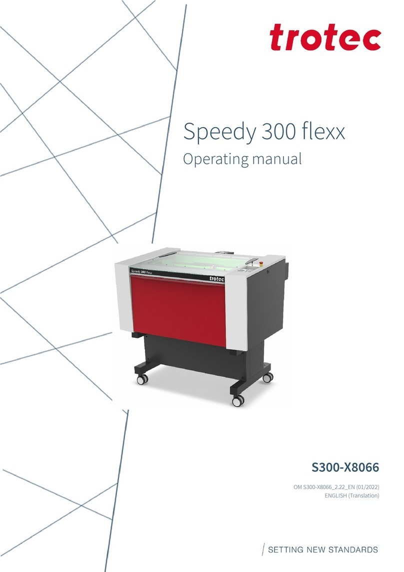
Trotec Speedy C12 User manual

NORMAL.DOT Gespeichert in:G:\Support\Dokumentationen_CDs\8003Speedy\Service Manual\Servicemanual 8003.doc Gespeichert am:2003/03/10
max Version 14
Seite 1 von 87
INDIVIDUALMAR
KINGSYSTEMS
SERVICE MANUAL
8003 Trotec SpeedyC12
8003 Trotec SpeedyC25
8003 Trotec SpeedyC50
8003 Trotec SpeedyC100
Trotec Produktions- u, Vertriebs GmbH
Linzer Straße 156
A-4600 Wels
Tel: ++43/7242/239-0
Fax: ++43/7242/239-7380
Version 1.1
January1999

NORMAL.DOT Gespeichert in:G:\Support\Dokumentationen_CDs\8003Speedy\Service Manual\Servicemanual 8003.doc Gespeichert am:2003/03/10
max Version 14
Seite 2 von 87
INDIVIDUALMARKINGSYSTEMS
This publication and it´s contents are proprietaryto Trotec Wels and are intended
solelyfor the contractual use ofTrotec customers.
This publication and it´s contents maynot be reproduced or distributed for anyother
purpose without the written permission ofTrotec Wels.
Notice
Trotec Wels does not assume anyliabilityarising out ofthe application or use ofany
products, curcuits or software described herein. Neither does it conveya license
under it´s patent rights nor the patent rights ofothers. Trotec Wels further reserves
the right to make anychanges in anyproducts described herein without notice. This
document is subject to change without notice.
CAUTION
Use ofcontrols or adjustments or performance ofprocedures other than
those specified herein mayresult in hazardous laser radiation exposure.

NORMAL.DOT Gespeichert in:G:\Support\Dokumentationen_CDs\8003Speedy\Service Manual\Servicemanual 8003.doc Gespeichert am:2003/03/10
max Version 14
Seite 3 von 87
INDIVIDUALMARKINGSYSTEMS
Table of contents
1. Main components of the Speedy laser engraver...................................................................5
2. Safety information.................................................................................................................7
General...............................................................................................................................................7
Laser Safety .......................................................................................................................................9
US laser classes.............................................................................................................................................. 9
SafetyInterlock System............................................................................................................................... 11
Dangers ofElectricity......................................................................................................................12
Emission indication and safety labeling........................................................................................13
Light Emitting Diodes.................................................................................................................................. 13
Audible Warning ......................................................................................................................................... 13
SafetyLabels ............................................................................................................................................... 14
3. Laser beamalignment on Speedy.......................................................................................15
4. Laser pointer adjustment ....................................................................................................20
5. Replacing the laser tube......................................................................................................22
Measuring the laser power:............................................................................................................23
Laser tube replacement (12W and 25W) ......................................................................................25
Laser tube replacement (50W and 100W) ....................................................................................26
6. Adjusting the Software........................................................................................................28
Adjusting the tickle power..............................................................................................................28
Adjusting the Power Correction factor CL:.................................................................................30
Adjusting the Offset parameters: ..................................................................................................31
Overtook adjustment:.....................................................................................................................33
Tab „correction“ in the service setup............................................................................................34
Tab „acceleration“ in the service setup.........................................................................................35
7. Adjusting the Hardware......................................................................................................36
Ruler adjustment and rectangularity adjustment ofthe motion system ...................................36
Howto check the ruler position................................................................................................................... 37
Ruler adjustment.......................................................................................................................................... 38
Rectangularityadjustment of the motion system.......................................................................................... 38
Table adjustment.............................................................................................................................40
8. Servicing the X axis.............................................................................................................44
9. Special instructions for X-belt tensioning..........................................................................50
10. Instructions for changing the X-gearing assembly..........................................................53
11. Servicing the Yaxis left part.............................................................................................56

NORMAL.DOT Gespeichert in:G:\Support\Dokumentationen_CDs\8003Speedy\Service Manual\Servicemanual 8003.doc Gespeichert am:2003/03/10
max Version 14
Seite 4 von 87
INDIVIDUALMARKINGSYSTEMS
12. Servicing the Yaxis right part ..........................................................................................60
13. The electric systemof the Speedy......................................................................................63
Block wiring diagram .................................................................................................................................. 64
Connector Assignment................................................................................................................................. 65
Checking the different components: ............................................................................................................ 66
14. Firmware Update...............................................................................................................67
Steps for updating the firmware................................................................................................................... 67
15. Network installation of Trotec laser engravers................................................................69
16. Software tips&tricks..........................................................................................................72
Rastering images in Corel Draw................................................................................................................. 72
Howto produce a Seal Press........................................................................................................................ 73
17. Marking metals using metal mark paint..........................................................................74
18. Speedy error codes.............................................................................................................75
Software feedback...........................................................................................................................75
Hardware feedback.........................................................................................................................78
19. FAQ´s.................................................................................................................................80
20. Recommended service intervals........................................................................................83
Warranty Regulations.....................................................................................................................83
Recommended replacement intervals for wear-and-tear parts..................................................85
21. Recommended tools...........................................................................................................86
22. Recommended spare parts Speedy - Starter Kit .............................................................87

NORMAL.DOT Gespeichert in:G:\Support\Dokumentationen_CDs\8003Speedy\Service Manual\Servicemanual 8003.doc Gespeichert am:2003/03/10
max Version 14
Seite 5 von 87
INDIVIDUALMARKINGSYSTEMS
1. Main components of the Speedylaser engraver
14
16
18
15

NORMAL.DOT Gespeichert in:G:\Support\Dokumentationen_CDs\8003Speedy\Service Manual\Servicemanual 8003.doc Gespeichert am:2003/03/10
max Version 14
Seite 6 von 87
INDIVIDUALMARKINGSYSTEMS
1 service socket 15 Power supply
2 autofocus sensor 10 X-axis
3 focussing head 11 keypad
4 engraving table 12 front lid
5 Y-axis connector 13 power socket
6 Polycarbonate door 14 service access panel
7 Laser tube cover 16 right interlock front lid
8 Exhaust connector 18 maintenance panel
9 Product ID label

NORMAL.DOT Gespeichert in:G:\Support\Dokumentationen_CDs\8003Speedy\Service Manual\Servicemanual 8003.doc Gespeichert am:2003/03/10
max Version 14
Seite 7 von 87
THEULTIMATE MARK
ING SOLUTION
2. Safetyinformation
Please read this chapter before operating or servicing a Speedylaser system!
General
The Speedyis an industrial apparatus with a high level ofsecurity. To guarantee a
safe operation it is necessaryto knowpotential dangers and avoid risks. The
dangers can be classified in three categories:
ìDangers caused bythe laser beam
ìDangers caused byelectricity
ìmechanical dangers
General SafetyInstructions
When working with the laser engraver please take note ofthe following safety
instructions:
1. Operation and service ofthe Speedymayonlybe performed bytrained
personnel.
2. Direct exposure ofskin or eyes to laser radiation maycause severe injuries.
The correct operation and service according to the manual can prevent
hazards. Operators mayperform procedures required inside the housing
onlythrough the interlocked door. Theymust never attempt to defeat the
door interlocks nor remove non interlocked portions ofthe housing.
3. The laser beam can ignite flammable materials. Therefore a fire
extinguisher should always be nearby. Do not store flammable materials
near or inside the laser engraver.

NORMAL.DOT Gespeichert in:G:\Support\Dokumentationen_CDs\8003Speedy\Service Manual\Servicemanual 8003.doc Gespeichert am:2003/03/10
max Version 14
Seite 8 von 87
THEULTIMATE MARK
ING SOLUTION
Working with the laser or setting the system to service mode without
supervision is not permitted.
4. Manymaterials, especiallynon-anodized aluminium, copper, silver and
gold, cannot be engraved with the laser engraver due to the verylow
absorption oflaser radiation. This means that most ofthe energyofthe
laser beam is reflected. Therefore those materials must not be present in
the laser beam path as otherwise a reflected laser beam could destroythe
cover ofthe laser unit.
5. Beam adjustment mayonlybe done bytrained personnel. Otherwise there
could be uncontrolled emission oflaser radiation. There are onlylimited
possibilities to adjust the mirrors due to a mechanic restriction. These
restrictions mayonlybe altered byauthorized personnel.
6. Before starting to work check whether the engraving ofthe material can
cause harmful fumes and whether the filters ofyour exhaust system are
suitable for these fumes. It is emphasized that it is the user’s responsibility
to obeythe national and regional threshold values for dusts, fumes and
gases. (The maximum concentration ofharmful substances must not be
exceeded). Never use the laser engraver without an exhaust unit with
appropriate filters for the treated material, as cutting or engraving certain
materials can produce vapours. Materials causing toxic or carcinogenic
smokes or fumes must not be treated without an exhaust unit with
appropriate filters. Furthermore it is the user’s responsibilityto ensure the
safe removal and disposal ofthe smokes and particles from the laser
machine according to the national and regional threshold values.
In the US reference should be made to Section 7.3 in the ANSI Z136.1-
1993 Standard for the safe use oflasers, to the exposure criteria in CFR
1910 Subpart Z from the US government, and to the Threshold Limit
Values (TLVs) published bythe American Conference ofGovernmental
Industrial Hygienists (ACGIH).
7. Please refer to the manual ofyour exhaust system regarding the change
intervals ofthe filters. We recommend to make a note ofthe last change of
filters on an adhesive label.
8. PVC (Polyvinylchloride) must not be processed with the laser engraver.
Ifyou have anyquestions please contact your supplier or Trotec.

NORMAL.DOT Gespeichert in:G:\Support\Dokumentationen_CDs\8003Speedy\Service Manual\Servicemanual 8003.doc Gespeichert am:2003/03/10
max Version 14
Seite 9 von 87
THEULTIMATE MARK
ING SOLUTION
Laser Safety
The safetyofa laser apparatus is defined byone offive safetyclasses: I (1),II (2),
IIIa (3a), IIIb (3b) and IV (4). The Speedy without laser pointer is in the EU safety
class 1 (with an installed laser pointer laser class 2) and therefore presents no
hazard to personnel when properlyused during normal operation or routine
maintanance. In the US all machines are classified as classII laser products. This
status is guaranteed bythe safetyhousing and safetydevices that are built into the
product.
Please be aware that improper operation ofthe laser apparatus nullifies this safety
class and allows under certain circumstances the emission ofradiation which can be
potentiallydangerous.
This laser engraving system contains a carbon dioxide (CO2)-laser class IV (4)
product, which emits an intensive and invisible radiation. Without safetydevices
the direct radiation and also diffuse reflected radiation is dangerous.
Please be aware: The Laser Radiation ofa CO2Laser is Invisible!
US laser classes
As posted bythe Center for Devices and Radiological Health (CDRH) regulation 21 CFR 1040.10
and 21 CFR 1040.11, the standard classification for lasers are as follows:
Class I laser product
No known biological hazard. The light is shielded fromanypossible viewing bya person and the
laser systemis interlocked to prevent the laser frombeing on when exposed. (large laser printers
such as the DEC LPS-40 has a 10mWHeNe driving it which is a Class IIIb laser, but the printer is
interlocked so as to prevent anycontact with the exposed laser beam, hence the device produces
no known biological hazard, even though the actuallaser is Class IIIb. This would also applyto CD
players and small laser printers, as theyare Class I devices).
Class II laser products
Power up to 1 milliwatt. These lasers are not considered a opticallydangerous device as the eye
reflex will prevent anyoccular damage. (I.E. when the eye is hit with a bright light, the eye lid will
automaticallyblinkor the person will turn thier head so as to remove the bright light. This is called
the reflex action or time. Class II lasers won't cause eye damage in this time period. Still, one
wouldn't want to lookat it for an extended period oftime.) Caution labels (yellow) should be placed
on the laser equipment. No known skin exposure hazard exist and no fire hazard exist.
Class IIIa laser products
Power output between 1 milliwatt and 5 milliwatt. These lasers can produce spot blindness under
the right conditions and other possible eye injuries. Products that have a Class IIIa laser should
have a laser emission indicator to tell when the laser is in operation. Theyshould also have a

NORMAL.DOT Gespeichert in:G:\Support\Dokumentationen_CDs\8003Speedy\Service Manual\Servicemanual 8003.doc Gespeichert am:2003/03/10
max Version 14
Seite 10 von 87
THEULTIMATE MARK
ING SOLUTION
Danger label and output aperature label attatched to the laser and/or equipment. A keyoperated
power switch SHOULD be used to prevent unauthorized use. No known skin hazard offire hazard
exist.
Class IIIb laser products
Power output from5 milliwatts to 500 milliwatts. These lasers are considered a definate eye
hazard, particularlyat the higher power levels, which WILL cause eye damage. These lasers
MUSThave a keyswitch to prevent unathorized use, a laser emission indicator, a 3 to 5 second
time delayafter power is applied to allowthe operator to move awayfromthe beampath and a
mechanical shutter to turn the beamoff during use. Skin maybe burned at the higher levels of
power output as well as the flash point ofsome materials which could catch fire. (I have seen
250mWargons set a piece ofred paper on fire in less than 2 seconds exposure time !) A red
DANGER label and aperature label MUSTbe affixed to the laser.
Class IV laser products
Power output >500 milliwatts. These CAN and WILL cause eye damage. The Class IV range CAN
and WILL cause materials to burn on contact as well as skin and clothing to burn. These laser
systems MUSThave:
A keylockout switch to prevent unauthorized use Inter-locks to prevent the system frombeing
used with the protective covers off Emission indicators to showthat the laser is in use Mechanical
shutters to blockthe beamRed DANGER labels and aperature labels affixed to the laser
The reflected beamshould be considered as dangerous as the primarybeam. (again, I have seen
a 1,000 watt CO2 laser blast a hole through a piece ofsteel, so imagine what it would do to your
eye !)
Registration of laser systems
Anylaser systemthat has a power output ofgreater than 5 milliwatts MUSTbe registered with the
FDA and Center for Devices and Radiological Health ifit has an exposed beam, such as for
entertainment (I.E. Laser light shows) or for medical use (such as surgery) where someone other
than the operator maycome in contact with it. (this is called a 'varience' and I have filled themout
and submitted themand theyARE a royal pain in the backside !)
Risks of Laser Radiation:
Ifthe built in safetymeasures are defeated or the laser is operated with the housing
open, there is a risk of setting clothing or other flammable materials on fire. Laser
energyat a power ofup to 150W(Model C100) at a wavelength of10,6 µm could be
present inside the housing.
Therefore operators can perform procedures required inside the housing onlywhen
the interlocked door has been opened. (A normal user must never defeat the door
interlocks or remove portions ofthe protective housing, except the machine is not
powered).
Therefore you must under no circumstances neither alter the laser tube unit nor
dismantle it nor set a system to work which has been altered or dismantled!

NORMAL.DOT Gespeichert in:G:\Support\Dokumentationen_CDs\8003Speedy\Service Manual\Servicemanual 8003.doc Gespeichert am:2003/03/10
max Version 14
Seite 11 von 87
THEULTIMATE MARK
ING SOLUTION
SafetyInterlock System
Your Speedyis equipped with an integrated safetyinterlock system which cuts off
the power ofthe laser tube immediatelyas soon as one ofthe doors is opened.
CAUTION
Do not attempt to alter the interlock system as that could result in
hazardous radiation exposure.
CAUTION
Technicians who are performing service procedures must be trained in
laser safety, and iftheyare defeating interlocks, theymust wear laser
protective eyewear designed for the 10,6µm CO2laser energy.
The top door, front door and the maintenance access panel are interlocked. Ifthe
interlocks are defeated access to laser class IV radiation is possible through anyof
these doors.
All other covers are not interlocked.
CAUTION
When a non interlocked cover is opened (and the machine is powered)
access to class IV laser radiation is possible.
These covers are labeled with „DANGER: INVISIBLE LASER RADIATION
WHEN OPEN. AVOID EYE OR SKIN EXPOSURE TO DIRECTOR
SCATTERED RADIATION“

NORMAL.DOT Gespeichert in:G:\Support\Dokumentationen_CDs\8003Speedy\Service Manual\Servicemanual 8003.doc Gespeichert am:2003/03/10
max Version 14
Seite 12 von 87
THEULTIMATE MARK
ING SOLUTION
Dangers of Electricity
When you open the covers ofthe engraving system there is the danger to get in
contact with parts under high voltage. Therefore it is absolutelynecessarythat
service and repair work is onlydone while the power supplyis unplugged. In any
case all safetylaws and standards in connection with electricitymust be obeyed.
IMPORTANT REMARK:
Usuallyyou do not need to get in touch with the electrical and electronic
components. In case you do that when servicing or repairing the laser engraver,
please be sure that you first plug off the power supply.

NORMAL.DOT Gespeichert in:G:\Support\Dokumentationen_CDs\8003Speedy\Service Manual\Servicemanual 8003.doc Gespeichert am:2003/03/10
max Version 14
Seite 13 von 87
THEULTIMATE MARK
ING SOLUTION
Emission indication and safetylabeling
Light Emitting Diodes
On the keypad ofthe laser engraver there is on the left side a red LED (light emitting
diode) which is illuminated when laser radiation is emitted.
Ifthe service plug is used to defeat the door interlocks, the red LED close to the
service button is flashing (which indicates that the machine nowis in service mode).
In this case the machine represents a laser class IV (4) product and special safety
provisions are necessary.
emission indicator
Audible Warning
When starting up the laser engraver without closing the cover there is an intermittent
beep. This indicates that the interlock system has not been checked yet. (You can
run the machine onlyifall interlock switches are closed). Close the cover ofthe laser
engraver to cause the machine to initialize.
On emitting a laser beam (which is called test pulse) bypressing the „TEST"- and
"SERVICE" button simultaneouslythere is a beep (as long as you keep the buttons
pressed) to remind you ofthe possible risks.

NORMAL.DOT Gespeichert in:G:\Support\Dokumentationen_CDs\8003Speedy\Service Manual\Servicemanual 8003.doc Gespeichert am:2003/03/10
max Version 14
Seite 14 von 87
THEULTIMATE MARK
ING SOLUTION
SafetyLabels
The laser safetystandards require that anyremovable panels that could permit
access to laser energyinclude laser safetylabels. These labels are visible before
and after opening a cover.
Labels with the name ofthe manufacturer, date ofproduction, description ofthe
product, model number, serial number and safetylabels are placed on the outer side
ofthe apparatus. All these labels are mounted when producing the laser engraver.
These labels must not be removed.
Ifthe labels are lost or damaged please contact Trotec. Replacements will be sent to
you free ofcharge. All labels and their exact place is mentioned in the user manual:
The labeling meets the standards
F21 CFR 1040 – Laser safety
and
FEN 60825-1(1994)

___________________________________________________________________________
NORMAL.DOT Gespeichert in:G:\Support\Dokumentationen_CDs\8003Speedy\Service Manual\Servicemanual 8003.doc Gespeichert am:2003/03/10
max Version 14
Seite 15 von 87
INDIVIDUALMARKINGSYSTEMS
3. Laser beam alignment on Speedy
What you need:
laser protection glasses (for CO2lasers)
the toolboxenclosed to your engraver
masking tape
CAUTION To make sure that there is no laser emission out ofa
controlled area establish a limited access area byusing non flamable
beam blocking curtains, temporarywalls or other enclosures.
CAUTION The laser beam alignment mayonlybe performed byservice
technichians that have been trained byTrotec and are familiar with the
hazards from lasers
CAUTION
Never expose anypart ofyour bodyto the beam as this could result in
serious injuries.
CAUTION
To do the alignment it is absolutelynecessaryto wear laser protection
glasses.
What you have to know:
The number ofthe mirrors is counted from the outlet ofthe laser tube to the
engraving head from one to three.
The whole alignment is done while your machine is running. To make sure the
system works at a suitable power level switch your machine off and on again.
The laser beam is invisible. To make it visible, you use adhesive tape. It is burned at
the spot, where it is hit bythe laser beam and shows so a mark.
The tolerable displacement (distance from burned dot to the centre) is one sixth of
the diameter ofthe mirror or hole where you check the position.

___________________________________________________________________________
NORMAL.DOT Gespeichert in:G:\Support\Dokumentationen_CDs\8003Speedy\Service Manual\Servicemanual 8003.doc Gespeichert am:2003/03/10
max Version 14
Seite 16 von 87
INDIVIDUALMARKINGSYSTEMS
Beam path of the Speedy:
CO
2
Laser Tube
Mirror No 2
Mirror No 3
Mirror No 1
Beam coupler
Aiming Laser diode
Beam path ofthe Speedymodel
X-Axis
Left Y-Axis Right Y-Axis
Maintenance
panel
Service access
panel

___________________________________________________________________________
NORMAL.DOT Gespeichert in:G:\Support\Dokumentationen_CDs\8003Speedy\Service Manual\Servicemanual 8003.doc Gespeichert am:2003/03/10
max Version 14
Seite 17 von 87
INDIVIDUALMARKINGSYSTEMS
What you have to do:
1. Disassemble the cover on the right side ofthe machine (10mm allen key).
2. Take your laser protection glasses and remove the greycover ofthe first mirror at
the rear ofyour laser (right side) wearing the sign „DANGER. INVISIBLE LASER
RADIATION WHEN OPEN. AVOID EYE OR SKIN EXPOSURE TO DIRECTOR
SCATTERED RADIATION.“
3. Remove mirrors #2 and #3.
Removal ofmirror #2
Removal ofmirror #3
mirror unit 3
cover ofmirror 1
mirror unit 2

___________________________________________________________________________
NORMAL.DOT Gespeichert in:G:\Support\Dokumentationen_CDs\8003Speedy\Service Manual\Servicemanual 8003.doc Gespeichert am:2003/03/10
max Version 14
Seite 18 von 87
INDIVIDUALMARKINGSYSTEMS
4. Put a piece ofmasking tape on the hole (black anodized aluminium part) in front
ofmirror #2.
alignment ofmirror no.1
5. Move the x-axis to the top position.
6. Press the test button, keep it pressed and then press the service button until you
see a little mark on the adhesive tape. (This is onlypossible ifall doors are closed
or a service plug is put into the socket). The mark should be in the centre ofthe
hole. (Ifyou don´t see a mark adjust the two brass screws at mirror #1 until you
can see a mark.
adjustments at mirror #1
7. Move the x-axis to the bottom position.
height adjustment
screw
left-right
adjustment screw
slider fixing screws
slider

___________________________________________________________________________
NORMAL.DOT Gespeichert in:G:\Support\Dokumentationen_CDs\8003Speedy\Service Manual\Servicemanual 8003.doc Gespeichert am:2003/03/10
max Version 14
Seite 19 von 87
INDIVIDUALMARKINGSYSTEMS
8. Repeat step 6, but this time tryto hit the spot that you´ve created first.
9. Repeat steps 5 to 8 until the two spots are exactlyat the same place.
10.Ifthe spot is not centered bring it to the center bymoving the slider ofmirror#1.
11.Replace mirror #2.
12.Put a piece ofmasking tape on the hole in front ofmirror #3.
checking the beamposition at mirror #3
13.Move the engraving head to the top right corner.
14.Again press the test button, keep it pressed and then press the service button
until you see a little mark on the adhesive tape.
15.Move the engraving head to the top left corner and adjust the two brass screws at
mirror #2 until you hit the spot created in step 14.
16.Repeat steps 13 to 15 to check the position. Ifnecessaryreadjust mirror #2.
17.Move the x-axis to the bottom position and check the alignment on the bottom left
position. Ifnecessarydo small corrections at mirror #1.
18.At the end check alignment on all four corners.
19.Assemble all parts again.
20.Nowyour engraver is aligned properly.

NORMAL.DOT Gespeichert in:G:\Support\Dokumentationen_CDs\8003Speedy\Service Manual\Servicemanual 8003.doc Gespeichert am:2003/03/10
max Version 14
Seite 20 von 87
INDIVIDUALMARKI
NGSYSTEMS
4. Laser pointer adjustment
Attention: To do the laser pointer adjustment it is absolutelynecessaryto wear laser
protection glasses!
What you need:
laser protection glasses
the toolboxenclosed to your engraver
a philips screwdriver
adhesive tape
What you have to know:
The alignment is done while your machine is running. To make sure the system
works at a suitable power level switch your machine ofand on again.
The laser beam is invisible. To make it visible, you use adhesive tape. It is burned at
the spot, where it is hit bythe laser beam and shows so a mark.
The tolerable displacement (distance from burned dot to the centre) is one sixth of
the diameter ofthe mirror or hole where you do the adjustment.
1.) After you´ve installed the laser pointer glue some paper tape on the beam
entrance hole ofthe engraving head (first remove the last mirror and the lens).
3
This manual suits for next models
3
Table of contents
Other Trotec Engraver manuals