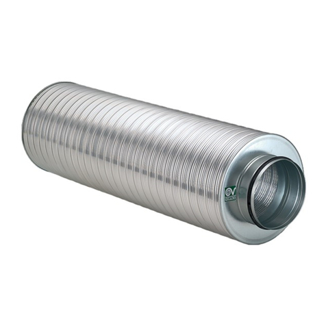
Trox Technik ATVC-100 User manual

Installation manual
Automatic exhaust valve
Type ATVC-100
Subject to change · All rights reserved ·
L-50-7-02e

Installation manual for automatic exhaust valve ATVC-100
2
Contents
1. General information 2
2. Safety and correct use 3
General safety notes 3
Standards and guidelines 4
Repair and replacement parts 4
Environmental protection / disposal 4
Staff qualifications 4
Limitation of liability 4
Personal protective equipment 4
Correct use 4
3. Transport, storage and packaging 5
Delivery check 5
Transport on site 5
Storage 5
Packaging 5
4. Product description 6
Brief description 6
Special features of ATVC-100 6
How it works 6
Dimensions 6
5. Technical data 6
6. Installation / commissioning 7
Device selection 7
Performance diagram 7
Setting the basic volume flow rate V08
Assembly 9
7. Electrical installation 9
Electrical connection 9
Connection diagram 9
8. Maintenance 10
Maintenance and cleaning 10
1. General information
This installation manual describes the automatic exhaust valve
type:
ATVC-100
To ensure correct functioning of the automatic exhaust valve,
it is essential to read the provided installation manual before
starting any work, and to comply with it. The manufacturer
does not accept any liability for any malfunction or damage
resulting from non-compliance with these instructions or non-
compliance with relevant statutory regulations. This installati-
on manual is intended for specialist consultants, developers,
and owners of the ventilation systems in which the automatic
exhaust valve is to be installed. This installation manual is also
intended for people conducting the following work:
- Transport and storage
- Installation
- Electrical connection
- Commissioning
- Maintenance
- Cleaning
For details on the ATVC-100, see:
- Brochure L-07-2-05d
The installation manual and the brochure can be downloaded
from
www.troxhesco.com.

Installation manual for automatic exhaust valve ATVC-100
3
2. Safety and correct use
General safety notes
VORSICHT!
Verletzungsgefahr an scharfen Kanten, Graten, spitzen
Ecken und dünnwandigen Blechteilen!
– Bei allen Arbeiten vorsichtig vorgehen.
– Schutzhandschuhe, Sicherheitsschuhe und
Schutzhelm tragen.
GEFAHR!
Stromschlag beim Berühren spannungsführender
Teile. Elektrische Ausrüstungen stehen unter
gefährlicher elektrischer Spannung.
Nichtbeachtung kann Tod, schwere Körperschäden
oder Sachschaden verursachen!
– An den elektrischen Komponenten dürfen nur
Elektrofachkräfte arbeiten.
– Vor Arbeiten an der Elektrik die Versorgungs-
spannung ausschalten.
WARNUNG!
Gefahr durch Fehlgebrauch! Fehlgebrauch des
Produktes kann zu gefährlichen Situationen führen.
Das Produkt darf nicht eingesetzt werden:
– in Ex-Bereichen.
– im Freien ohne ausreichenden Schutz gegen
Witterungseinflüsse.
– in Atmosphären, die planmässig oder ausserplan-
mässig aufgrund chemischer Reaktionen eine
schädigende und/oder Korrosion verursachende
Wirkung auf das Produkt ausüben.
WARNUNG!
Verletzungsgefahr bei unzureichender Qualifikation!
Unsachgemässer Umgang kann zu erheblichen Personen-
und Sachschäden führen.
– Alle Tätigkeiten nur durch dafür qualifiziertes Personal
in der Gebäudetechnik-Branche durchführen lassen.
VORSICHT!
Beschädigung des Produktes durch unsachgemässe
Behandlung! Gerät vor Inbetriebnahme auf Schäden
und Verunreinigung prüfen und beheben!
Unsachgemässer Umgang kann zu erheblichen
Sachschäden am Produkt führen.
– Keine säurehaltigen oder scheuernden Reinigungs-
mittel verwenden.
– Klebstoffe von Klebebändern können Farbschäden
verursachen.
– Unverhältnismässige Feuchtigkeit kann zu
Farbschäden und Korrosion führen.
– Nur ausdrücklich spezifizierte Reinigungsmittel,
Fette und Öle benutzen.

Installation manual for automatic exhaust valve ATVC-100
4
Standards and guidelines
For all work on the automatic exhaust valve, the following regu-
lations and guidelines must be observed among others:
- Product Safety Laws (PrSG)
- EKAS provisions
The local regulations for health and safety at work and general
safety regulations also apply.
Repair and replacement parts
To maintain the function, use only original TROX HESCO
Schweiz AG replacement parts.
Environmental protection / disposal
To protect the environment keep the following in mind:
- The packaging of the automatic exhaust valve must be dis-
posed of in an environmentally- friendly
manner.
- The automatic exhaust valve must be disposed of properly
by an authorised agent after its final decommissioning.
- Dispose of electronic components according -
to the national electronic waste regulations.
Qualied sta
Skilled qualied electrician
Skilled qualified electricians are individuals who have sufficient
professional or technical training, knowledge and actual ex-
perience to enable them to work on electrical systems, under-
stand any potential hazards related to the work under conside-
ration, and recognise and avoid any risks involved.
Specialist personnel
Specialist personnel are individuals who have sufficient profes-
sional or technical training, knowledge and actual experience to
enable them to carry out their assigned duties, understand any
potential hazards related to the work under consideration, and
recognise and avoid any risks involved.
Limitation of liability
The information in this manual has been compiled with refe-
rence to the applicable standards and guidelines, the state of
the art, and our expertise and experience of many years.
The manufacturer does not accept any liability for damages
resulting from:
- Non-compliance of these instructions
- Improper use
- Operation or handling by untrained individuals
- Unauthorised modifications
The actual supply package may differ from the information in
this manual for special versions, additional order options or as
a result of recent technical changes.
Personal protective equipment
Personal protective equipment must be worn for any work in
order to reduce health or safety hazards to the minimum.
The appropriate protective equipment for a job must be worn
for as long as the job takes.
Industrial safety helmet
Industrial protective helmets protect the head from falling ob-
jects, suspended loads and knocks against
stationary objects.
Protective gloves
Protective gloves protect hands from friction, abrasions, punc-
tures, deep cuts, and direct contact with hot surfaces.
Safety shoes
Safety shoes protect the feet against crushing, falling parts,
and from slipping on slippery ground.
Correct use
The automatic exhaust valve ATVC-100 is suitable for installati-
on in multi-storey residential and commercial buildings, hotels,
schools, etc. with central exhaust air systems.
The ATVC-100 can be installed in new buildings and in refur-
bishment projects.

Installation manual for automatic exhaust valve ATVC-100
5
3. Transport, storage and packaging
Delivery check
Upon delivery, carefully remove the packaging and check the
unit for transport damage and completeness. In case of any
damage or an incomplete shipment, contact the shipping com-
pany and the supplier immediately. Put the product back into
its packaging after the delivery check to protect it from dust
and contamination.
Transport on site
Please note:
- When unloading the delivery and transporting on-site,
proceed with care and observe the symbols and notices-
on the packaging.
- Devices should preferably be transported to the installation
location in their
original packaging.
- Use only lifting and transport gear
designed for the required load.
- Always secure the load against tipping and falling.
- Cumbersome equipment should be transported with at least
two people to
prevent injury and damage.
Storage
Please note:
- Store the product only in its original packaging.
- Protect the product from the effects of weather.
- Protect the product from humidity, dust and contamination.
- Storage temperature: -10 °C to +30 °C..
- Relative humidity: maximum 95%, no condensation
Packaging
Properly dispose of packaging material.
Befestigungs- und Montagematerial
Befestigungs- und Montagematerialien sind, soweit nicht
anders angegeben, kein Bestandteil der Lieferung und
müssen bauseits, abgestimmt auf die jeweilige Einbausitua-
tion beigestellt werden.

Installation manual for automatic exhaust valve ATVC-100
6
4. Product description
Brief description
The automatic exhaust valve is an exhaust air device control-
led by an electric external power supply. It is normally closed
or only slightly open to enable a basic volume flow rate. Air is
only extracted at a higher operating volume flow rate when the
corresponding switch contact is closed.
Special features of the ATVC-100
- Heating energy can be saved thanks to targeted ventilation
(basic volume flow rate/operating volume flow rate).
- No high volume flow rate during brief occupation of the
room thanks to the installed start delay.
- Silent opening and closing of exhaust valve.
- Exhaust valve and electro-thermal drive made from proven
components.
- Easy assembly.
- Taking the diversity factor into account,
a smaller roof fan and riser duct
can be selected.
- The exhaust valve can be closed tightly.
- Connection to the normal lighting network 230V 50Hz wit-
hout
additional delay relay (follow-up ventilation) or transformers.
How it works
When the circuit is closed, the electro-thermal drive heats up
and causes the valve disc to open within 2 to 4 minutes (delay
during brief occupation of the room). Air is exhausted through
the opening between the valve housing and the valve disc.
The valve stroke (6 mm) is always the same, i.e. the valve disc
always moves from the minimum setting to the maximum valve
opening. In the minimum setting, the exhaust valve can either
be closed or opened. Since the valve stroke is always the
same, the operating volume flow rate cannot be freely selected,
but is dependent on the minimum setting. The exhaust valve
stays open at the maximum valve stroke for as long as the
circuit is closed. Once the circuit has been interrupted, the
automatic exhaust valve remains open for follow-up ventilati-
on for approx. 5-8 minutes before it starts to move back to its
minimum setting slowly and silently.
Dimensions
1 Valve casing
2 Valve disc
3 Electro-thermal actuator
4 Tappet
5 Knurled nut
6 Electrical connection
7 Spring element (3 pieces)
8 Foam seal
5. Technical data
Nominal voltage 230V 50 Hz
Power consumption – initial 60 W
Power consumption – when run-
ning
8 W
Max. ambient temperature 30° C
Opening time 2 to 3 min.
Closing time 5 to 8 min.
Device for connection opening Ø 100 mm

Installation manual for automatic exhaust valve ATVC-100
7
6. Installation / commissioning
Device selection
The exhaust valve is determined by the following data:
- Stat. pressure loss ps(Pa)
- Basic volume flow rate (m3/h)
- Operating volume flow rate (m3/h)
Using this data, the stat. pressure loss and only one of the two
volume flow rates can each be freely selected.
The performance diagram (see below) is used to determine the
following:
- Number of rotations
- Residual volume flow rate
- Acoustic data.
Note that, if the minimum setting is selected, then the corre-
sponding operating volume curve must be taken into account.
Performance diagram
Example (as plotted)
Given:
- Stat. pressure drop ps= 40 Pa
- Operating volume flow rate V = 80 m3/h
Solution:
- Rotations for minimum setting 1
- Basic volume flow rate: Vo = 10 m3/h
- Sound power level for:
Basic volume flow rate <25 dB(A)
Operating volume flow rate approx. 38 dB(A)
10
20
30
40
50
100
Druckabfall ps[Pa]
15
60
80
LwA = 25 dB(A)
30 dB(A)
0
1
2
3
4
5 10 15 20 30 40 50 60 30 40 50 100 150 200
Grundvolumenstrom
‡
o[m³/h] Betriebsvolumenstrom
‡
[m³/h]
10
20
30
40
50
100
Druckabfall ps[Pa]
15
60
80
35 dB(A)
40 dB(A) 45 dB(A)
40 dB(A)
35 dB(A)
LwA = 30 dB(A)
ps
10
20
30
40
50
100
Perte de pression ps[Pa]
15
60
80
LwA = 25 dB(A)
30 dB(A)
0
1
2
3
4
5 10 15 20 30 40 50 60 30 40 50 100 150 200
Débit d'air de base ‡o[m³/h] Débit d'air de service ‡[m³/h]
10
20
30
40
50
100
Perte de pression ps[Pa]
15
60
80
35 dB(A)
40 dB(A) 45 dB(A)
40 dB(A)
35 dB(A)
LwA = 30 dB(A)
ps
10
20
30
40
50
100
Pressure drop ps[Pa]
15
60
80
LwA = 25 dB(A)
30 dB(A)
0
1
2
3
4
5 10 15 20 30 40 50 60 30 40 50 100 150 200
Basic air volume rate ‡o[m³/h] Operating air volume rate ‡[m³/h]
10
20
30
40
50
100
Pressure drop ps[Pa]
15
60
80
35 dB(A)
40 dB(A) 45 dB(A)
40 dB(A)
35 dB(A)
LwA = 30 dB(A)
ps

Installation manual for automatic exhaust valve ATVC-100
8
Setting the basic air volume ow rate V0
The automatic exhaust valve is delivered ex-works in a closed
condition (basic volume flow rate V0 = m3/h). If a basic volume
flow rate is required, this must be set as follows:
1 Valve casing
2 Valve disc
3 Electro-thermal actuator
4 Tappet
5 Knurled nut
Place the exhaust valve on a firm base as shown, e.g. on a
table, and loosen the brass knurled nut "5" by turning it one
rotation in a clockwise direction.
Hold the exhaust valve at the electric drive as shown and, using
one finger of your free hand, open the valve disc "2" by turning
it the required number of rotations in an anticlockwise direction.
Place the exhaust valve on a firm base as shown, e.g. a table,
hold it firmly with one hand against the base and tighten the
knurled screw "5" in an anticlockwise direction up to the tappet
"4".
Note: It is important that the valve disc does not rotate during
this operation.
The exhaust valve is now set.
1
5
2
4
3
5
2
45

Installation manual for automatic exhaust valve ATVC-100
9
Assembly
Once the required volume flow rate has been set and the
electric connection has been completed, the automatic exhaust
valve can be inserted into the appropriate opening so that the
casing is flush with the wall. The exhaust valve is held in the
opening by 3 spring elements.
Initial commissioning
Before you start commissioning:
- Check that the air terminal devices are seated correctly.
- Remove protective film.
- Ensure that all air terminal devices are clean and free from
residues and foreign matter.
- Check that electrical connections (if any) have
been correctly made.
- Check that the fixing and connection -
with the air duct is correct.
Volume ow rate balancing
When several diffusers are connected to just one volume flow
controller, it may be necessary to balance the volume flow
rates.
7. Electrical installation
GEFAHR!
Stromschlag beim Berühren spannungsführender
Teile. Elektrische Ausrüstungen stehen unter
gefährlicher elektrischer Spannung.
Nichtbeachtung kann Tod, schwere Körperschäden
oder Sachschaden verursachen!
– An den elektrischen Komponenten dürfen nur
Elektrofachkräfte arbeiten.
– Vor Arbeiten an der Elektrik die Versorgungs-
spannung ausschalten.
Electrical connection
Location of the electric cable
It is best to lead the electrical cable into the round air extract
opening.
Connection diagram
A 2-pin plug-in connector with protective contact is provided
for the electrical connection on site. Plug "A" can be removed
from the connector plate "C" after loosening the central screw
"B". With the central screw "B" removed from the plug "A", the
insert "F" can be pressed out with a screwdriver at the point
marked "D".

Installation manual for automatic exhaust valve ATVC-100
10
8. Maintenance
Maintenance and cleaning
Please note:
- Clean surfaces with a damp cloth.
- Only use commercially available, non-corrosive cleaning
agents-
for cleaning.
- Do not use cleaning agents that contain chlorine.
- The use of cleaning tools for removing persistent
contamination, e.g. scrubbing sponges and scouring agents,
can damage the surface and is not permitted.
- All technical components can be replaced
if defective.
GEFAHR!
Stromschlag beim Berühren spannungsführender
Teile. Elektrische Ausrüstungen stehen unter
gefährlicher elektrischer Spannung.
Nichtbeachtung kann Tod, schwere Körperschäden
oder Sachschaden verursachen!
– An den elektrischen Komponenten dürfen nur
Elektrofachkräfte arbeiten.
– Vor Arbeiten an der Elektrik die Versorgungs-
spannung ausschalten.
Design subject to change (06/2017)
Table of contents
Other Trox Technik Control Unit manuals
Trox Technik
Trox Technik Auranor FMS-A User manual
Trox Technik
Trox Technik XS User manual

Trox Technik
Trox Technik EM-BAC-MOD-01 User manual

Trox Technik
Trox Technik EM-IP Instruction sheet
Trox Technik
Trox Technik TROX UNIVERSAL User manual
Trox Technik
Trox Technik HESCO HFA User manual
Trox Technik
Trox Technik EM-TRF User manual

