Truckman Roll-Top Xtreme User manual
Tools Required for Assembly ..................................... 1
Before You Start .......................................................... 1
Drain Hole Locations.................................................... 1
STEP 1: Remove From Packaging, and
Hardware and Packaging Contents ............................. 1
STEP 2: Positioning Canister ..................................... 2
STEP 3: Installing Rails .............................................. 2
STEP 4: Installing Top Cover ...................................... 4
STEP 5: Installing Clamps........................................... 5
STEP 6: Installing Rail Kickstands .............................. 6
STEP 7: Installing Tailgate Drain Tubes...................... 7
STEP 8: Lubricating Sweep Seals .............................. 8
STEP 9: Installing Canister Drain Tubes .................... 8
STEP 10: Attach the Pull Strap .................................. 8
Operating Instructions .................................................. 9
Maintenance ................................................................ 9
Warranty Statement ..................................................... 10
ARV1-1705
INSTALLATION INSTRUCTIONS
VOLKSWAGEN AMAROK
TABLE OF CONTENTS
Truckman
Unit 14 Narrowboat Way
Dudley
West Midlands
DY2 0EZ
Telephone: +44 (0) 1384 485405
http://www.truckman.co.uk
UNCONTROLLED DOCUMENT
1
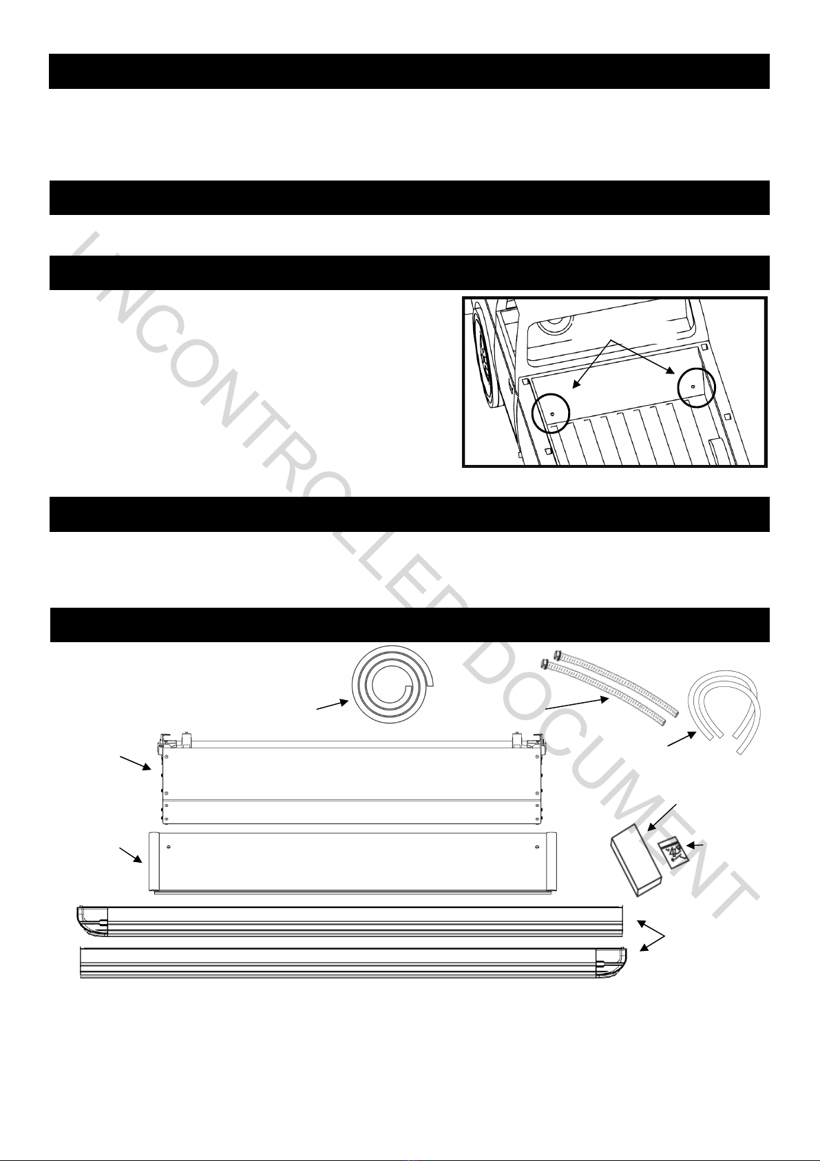
This tonneau cover is designed to carry rainwater from the cover
into the canister and then out through the drains. Most truck
models have standard OE drain holes or plastic/rubber access
ports in the front of the truck bed. Check to make sure your truck
has the OE drain holes so that drilling into the sheet metal is not
required. If drilling is necessary, be sure to check the underside
of the truck bed for the best location. The holes should be
located near the side and as far forward as possible. Use a drill
bit suitable for sheet metal (such as a taper drill or step drill). Drill
drain tube clearance holes at 3/4” (19mm). This will need to be
done before installing the cover.
TOOLS REQUIRED FOR ASSEMBLY
BEFORE YOU START!
CANISTER DRAIN HOLE LOCATIONS:
STEP 1: REMOVE FROM PACKAGING AND REVIEW CONTENTS
Tape Measure Side Cut or Needle Nose Pliers Masking tape 7/16” (11mm) Nut Driver
#2 Phillips Screwdriver Utility Knife
Note: There should be no drilling into the truck body needed on most standard or full-size trucks.
PACKAGING CONTENTS:
Complete
Canister
Assembly
Top Cover
Canister Drain
Tubes
Clamp Pack
Rails (Left
and Right)
Hardware
Pack
Drain Tube
Read the instructions carefully before you start. If you have any questions regarding the installation please call
Truckman at +44 (0) 1384 485405.
Top Cover
Foam
Tailgate Drain
Tubes
A complete unit will consist of the Rails, Top Cover, Canister Assembly, Clamp Pack, Hardware Pack, Foam and
Drain Tubes. Remove the components from the packaging carefully in order to avoid loss or damage. Perform a
quick inventory of the packaging contents to ensure the kit is complete.
UNCONTROLLED DOCUMENT
2
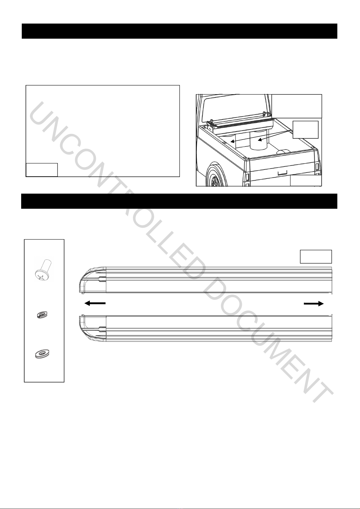
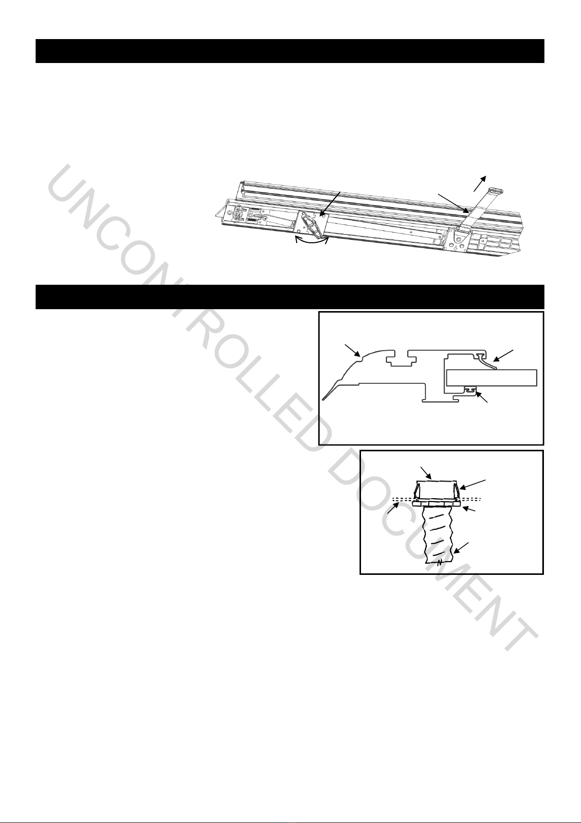
Use the Pull Strap and the canister body to lift and steady the
unit. Wrap the Pull Strap around the center of the canister a
couple times and double it up in your hand. (If you have
someone to help you, you can jump to step 3 and install the
assembled canister and rails on the truck)
Place the Canister in truck bed just behind the cab
and center it from side to side. You will need to
place the canister on elevating objects, such as the
box the canister came in or buckets. Note:
Ensuring that the canister is centered in the bed
will help with rail installation in the next step.
STEP 2: POSITIONING CANISTER
STEP 3: INSTALLING RAILS
FIG. 2A
FIG. 2B
Elevating
Canister needs to be
high enough to have
rail install clearance
Remove the protective paper from the foam on the underside of the Rail flanges. This is for packaging purposes
only.
Next identify the left and right side rails (FIG 3A). The rail flange and foam go towards the outside of the truck bed.
Left Rail
Right Rail
Tailgate End Cab End
HARDWARE
USED:
1/4-20 X 5/8”
RAIL SCREW
1/4” FLAT
WASHER x 2
1/4” LOCK
WASHER x 2
FIG. 3A
Note: Figure above is for reference
only and your supplied rails may be
slightly different.
UNCONTROLLED DOCUMENT
3
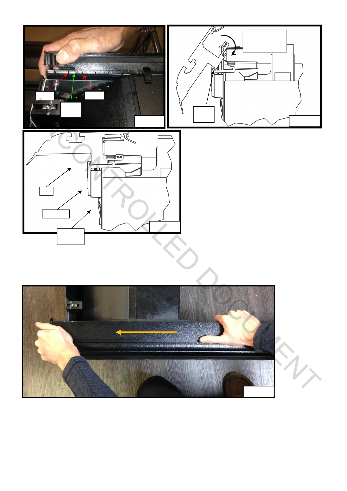
FIG. 3C
FIG. 3D
FIG. 3E
FIG. 3B
3rd Rib 4th Rib
Rail Sill
Vertical Outside
Groove
First make sure your handle latches are in, this
makes the rail install much easier (FIG 3F).
WARNING: IF YOU DO NOT HAVE THE LATCHES
IN, THE HANDLE WILL CATCH THE RAIL AS YOU
ATTEMPT TO SLIDE IT IN.
Next line up the Rail sill vertical between the 3rd and
4th Rib of the Rail Guide Spacer (FIG 3B). Then
hook the Outside Groove of the rail into the Rail
Guide and rotate down until the rail and rail guide are
level (FIG 3C & 3D). Now push the rail all the way
forward (FIG 3E). Finally you can install the Rail
Screw, Flat and Lock Washer securing the rail to the
canister (FIG 3G).
Rail Guide
Spacer
Rotate Down while
remaining in
Outside Groove
Rail Guide
Rail
UNCONTROLLED DOCUMENT

4
STEP 4: INSTALLING THE TOP COVER
Shut the tailgate and pull the rails back until the tailgate cap seals have good engagement
with your tailgate. A good way to check for proper engagement is to make sure the bottom
cap and tailgate have a 6mm gap (FIG 4A).
FIG. 4A
Tailgate
Bottom Cap
Tailgate
Cap Seal
The Rail shown is for
REFERENCE and may
not exactly match your
particular Rail geometry.
Canister Groove
Left Rail
Flat Washer
Lock Washer
Rail Screw
Canister
FIG. 3G
BLACK TOP COVER
SCREW x 2
180cm OF FOAM
INSTALLATION
TOOL x 1
FIG. 4C
Another way to set the tailgate cap seals is to use
the Tailgate Seal Gauge as shown in figure 4B &
4C. You should be able to just slide the Tailgate
Seal Gauge in between the Tailgate Cap Seal and
the Bottom Cap.
WARNING: Proper Tailgate Cap Seal
Engagement is important for getting the best
possible water resistance out of your cover!
BR Gauge
Tailgate Seal
Gauge
FIG. 4B
FIG. 3F
Installing the rails is easier with the handle latches
in. For information on handle operation reference
Figure 11A.
Latches In
Latches Out
6mm
UNCONTROLLED DOCUMENT

5
First assemble 4 clamp assemblies as shown in Figure 5A. Then Push the rails so that the brackets are resting
on the truck bed rail. Next Slide the pinch clamps on all 4 brackets (FIG 5B). Lightly Tighten the turn knobs
making sure that the pivot is in the orientation shown in Figure 5C so that is rotates up and reacts off the bottom
of the truck side sill. Figure 5D shows a cross section of how the clamps should look.
FIG. 5A
FIG. 5B
FIG. 5C
Flat
Washer
Lock
Washer
FIG. 5D
Pinch Clamp
Rail
Bracket
Truck
Bed Rail
Turn
Knob
Pivot
Shim
STEP 5: INSTALLING THE CLAMPS
Next mark where the front of the rails sit and mark this position with masking tape, this will be a guide for placing
your foam. (FIG 4D). Now pull the cover back until there is room to apply the foam. Lay the foam on the front sill of
the truck from rail to rail, trimming the excess with a utility knife (FIG 4E).
Now move the rails and canister back on the foam and double check that your tailgate seal engagement is good.
You can now install your top cover with the two included screws while making sure it aligns with the front of your
rails (FIG 4F).
WARNING: Proper top cover foam installation is important for getting the best possible water resistance out
of your cover!
FIG. 4E
FIG. 4D
Foam
Rail
Top Cover
FIG. 4F
UNCONTROLLED DOCUMENT

6
Once the clamps are lightly tightened,
measure the Between-the-Rail dimension at
the front and rear of the truck (FIG. 5E).
Another way to ensure proper fit is to check
the side to side play of the handle assembly
at the canister and at the tailgate end of the
rails. There should be, at the minimum,
enough play to allow the cover to move
freely with no drag and at a maximum 3mm
per side. If you push the cover you one side
you should not be able to fit the Between-the
-Rail gauge between the Rail metal and
Handle Stop on the opposite side. More than
3mm per side may result in the cover
opening unintentionally and in severe cases
it may fall between the rail tracks and
damage the cover. There are “Stick on
Shims” in the hardware pack that can be
added to the brackets if too loose.
Part number is on the
serial number label in
the upper left corner of
the canister (looking
from tailgate).
Rail
Metal
Handle
Stop
FIG. 5F
Slide the 4 Grip pieces on the rails as shown in Figure 6A. Position The Grip piece so that it is just beyond the
Relief Machining Figure 6B. Kickstands should go on the Tailgate and canister end of each rail (FIG. 6C).
STEP 6: INSTALLING THE RAIL KICKSTANDS
Grip
Rail
FIG. 6B
FIG. 6A
Relief Machining
BR Front
BR Rear
FIG. 5E
TAILGATE END
CANISTER END
FIG. 6C
PART BETWEEN
NUMBER THE RAILS
AR and AM2083 54 1/16 (137.3 cm)
BTR
UNCONTROLLED DOCUMENT

7
STEP 7: INSTALLING TAILGATE DRAINTUBES
To install the tailgate drain tubes you need to find suitable holes in
the rear stiffener of your truck bed. Figure 7B shows possible hole
locations.
Next you will screw the drain tube onto the drain fitting and slide it
on the tailgate cap as shown in figure 7C. There is an interference
bump on the cap that will lock the drain fitting in place. Next you will
need to thread the drain tube in the desired hole and trim the length
of the tube if needed. If there are no holes on the tailgate side of
your truck you will need to drill holes (5/8” or 16mm), make sure to
check for wires you could damage first.
FIG. 7A
FIG. 7B
Tailgate Drain
Fitting
Tailgate Drain
Tube
Tailgate Cap
TAILGATE DRAIN
TUBES X 2
DRAIN FITTINGS
X 2
Fasten the pre assembled Kickstand Assembly on the Grip using the provided mounting bolt, flat washer, lock
washer and wingnut (FIG. 6E). Next swing up the kickstand so that the adjusting bolt is as perpendicular to the Truck
Bed wall as possible (FIG. 6F). If you need more or less engagement you can change the length of the Kickstand by
flipping Kickstand Base (FIG. 6G). Tighten the Adjusting Bolt first by using the vinyl cap for quick adjustment, fine
tuning and higher torque can then be applied using the Turn Knob. Once the rails are level double check that your
Between-the-Rail dimension is still good and you can fully tighten the clamps.
FIG. 6F
Truck Bed
Wall
Adjusting
Bolt
Turn
Knob
Vinyl
Cap
Kickstand
Base
Flipping
Base
FIG. 6G
Longer Orientation Shorter Orientation
Mounting
Bolt Lock
Washer Wingnut
FIG. 6E
Flat
Washer
UNCONTROLLED DOCUMENT

8
Possible Hole
Locations
FIG. 7C
Locate the sweep seals (rubber weather strips) on the rails.
Open the provided 303 brand protectant sponge pack (find it
adhered to the underside of the top cover) and wipe the
underside of the sweep seal and the top of the wear strip.
Extend the cover to the tailgate. Use an Allen wrench if
needed to carefully draw out the sweep seal (seal should be
angled outwards toward the cover – not rolled in toward the
bed rail). (Fig. 8A)
Proper care and placement of the sweep seal will ensure the
smooth operation of the cover. Alcohol, petroleum based or
silicon-based UV Protectants such as Armor-All® should be
avoided and ARE NOT recommended for our covers.
STEP 8: LUBRICATING & PLACING THE SWEEP SEALS
Rail
Cover/Fabric Panel
Wearstrip
Sweep Seal
FIG. 8A
First, ensure that the Foam Washer is in place on the Drain Fitting as this washer
will help prevent water leakage. Next, test fit the drain tube to determine the length
you want to trim it. Always caution on the long side. Trim the end that will be
inserted through the truck bed using the wire cutters or a utility knife.
With the cover opened, insert the drain tube fittings into the pre-drilled holes on the
underside of the canister by pushing them in place from under the canister. Drain
Fitting should click into place.
Place the other end of the drain tube through the plastic/rubber access port or
through the pre-drilled holes in the floor or the front wall of the truck bed. If routing
through the front wall, ensure that the drain tubes are inserted and directed down
so water flows out of the truck.
To remove the drain tubes reach under the canister, grab the drain tube fitting and
turn it while applying light downward pressure. When the retaining tabs align with
notches in the bottom of the canister the Drain Tube and Fitting will drop out.
STEP 9: INSTALLING CANISTER DRAIN TUBES
Notch
Feature
Foam
Washer
Drain Fitting
Drain
Tube
FIG. 9A
Retract the cover the fully open position. Attach the
10cm Velcro strip onto the Velcro strip already
attached to the pull strap. Pull the pull strap over to
the driver’s side rail and remove the tape from the
10cm Velcro strip. Then apply the Velcro strip onto the
underside of the rail at your desired position. This will
hold the pull strap off of the floor and out of the way
when cargo is being stored in the truck bed.
STEP 10: ATTACH THE PULL STRAP
10cm VELCRO
STRIP
FIG. 10A
UNCONTROLLED DOCUMENT
9
To help keep your Retractable Tonneau Cover looking it’s best,
we recommend washing it the same as caring for your truck
finish. However you should not wax your cover. Using a citrus-
based vinyl cleaner and protectant such as 303 brand
protectant will keep your cover looking like new.
To assure quiet, smooth operation, periodically apply a
generous amount of the same 303 brand or equivalent
protectant to a rag and wipe out the inside of the rails the
underside of the sweep seal and the top of the wear strip.
Repeat as needed until these components are cleaned of debris
and well lubricated.
Ensure proper placement of the sweep seal as shown in step 8. Re-apply
protectant/lubricant if the cover begins squeaking or sticking during use.
(FIG. 8A)
Alcohol, petroleum based or silicon-based cleaners such as
Armor-All® should be avoided and ARE NOT recommended for our
covers.
It is important to open and close the cover regularly; the spring that
operates the cover is self-lubricated and regular use assures that it stays
in proper working condition.
Periodically remove the Top Cover and clean out the inside of the canister.
Drain tubes may become clogged overtime and should be removed and cleaned. To remove the drain tubes reach
under the canister, grab the drain tube fitting and turn it while applying light downward pressure. When the retaining
tabs align with notches in the bottom of the canister the Drain Tube and Fitting will drop out. (FIG. 9A and FIG. 12A)
Drain Tube Fitting
Retaining Tab
Foam Washer
Canister
Drain Tube
FIG. 12A
MAINTENANCE
Rail
Cover/Fabric Panel
Wearstrip
Sweep Seal
FIG. 8A
1. To open the cover, turn the actuator knob clockwise 90o until it clicks in the open position. This retracts the
latches into the handle and the cover is free to roll open into the canister. A tug on the pull strap will release the
latch and allow the cover to lock into the rails.
2. To latch the cover in one of the mid-range positions, pull it back just beyond the position desired and allow the
cover to retract until it latches into place. Latching positions are located every 30cm along the rails. The clicking
sound is the spring-loaded latches mounted inside the handle. The latches are designed to bypass the latching
positions as the cover is being closed and to stop the cover as it is being retracted.
3. To close the cover, pull on the
strap to draw it back toward the
tailgate. When it is within easy
reach, grasp the handle by the
hand grip and pull the cover to
the latching position against
the tailgate.
OPERATING INSTRUCTIONS
ACTUATOR KNOB PULL
STRAP
FIG 11A
UNCONTROLLED DOCUMENT

10
On your purchase of a Roll-Top Xtreme by Truckman. We are confident that you will get many years of trouble
free service from this accessory on your truck.
Truckman (hereinafter referred to as the MFG.) warrants each new
Roll-Top Xtreme retractable truck bed cover to the original owner as
follows:
FOR A PERIOD OF 3 YEARS FROM THE DATE THE UNIT IS
DELIVERED TO THE FIRST PURCHASER:
• Delamination of the Fabric Panel Assembly
• Failure of the Continuous Tension Spring
• All hardware and components
ITEMS NOT COVERED UNDER WARRANTY FOR ANY PERIOD
OF TIME:
• Rips, tears, or discoloration of the Fabric Panel material
• Seals and gaskets
• Water intrusion from any source
• Dealer and/or purchaser installed parts and accessories
CERTAIN CONDITIONS WILL VOID ALL WARRANTY.
These conditions include:
• Use for any purpose other than normal private use including
rental and promotion
• Altering the retractable truck bed cover in any manner without
written approval of the MFG
• Misuse, negligence or accident
• Installation of any part or accessory without written approval from
the MFG
CONGRATULATIONS!
CLAIMS:
If you have any warranty issues, please contact Truckman at +44 (0) 1384 485405 with the original invoice, the Unit Model and Serial Number.
After determining the validity of the warranty claim, Truckman will ship a replacement part prepaid to the customer. Labour costs to replace
defective parts are the responsibility of the purchaser.
CONDITIONS AND LIMITATIONS
This warranty is subject to certain conditions and limitations including,
but not limited to, the following:
• Any part of a Roll-Top Xtreme by Truckman retractable tonneau
that is found to be defective under the terms of this warranty will
be repaired or replaced using either new or reconditioned parts at
the discretion of the MFG.
• In determining what constitutes a failure under the terms of this
warranty the decision of the MFG shall be final.
• This warranty is extended to the original purchaser only and is not
transferable to subsequent purchasers.
• The MFG does not accept any responsibility in connection with
the installation of any of its products by its dealers or agents.
• The MFG does not undertake responsibility to any purchaser for
warranty express or implied by any of its dealers, distributors or
agents beyond that which is contained herein.
• Without regard to an alleged defect of its products the MFG under
any circumstances does not assume responsibility for loss of
time, inconvenience, revenue, or other consequential damage
including, but not limited to, expenses for telephone, food,
lodging, travel, loss or damage to the vehicle the products are
installed on or loss or damage to personal property of the
purchaser or user of the products.
• The MFG reserves the right to make changes in the design of,
improvements to, or warranty of its products without imposing any
obligation upon itself to provide the same for any products
theretofore manufactured.
Some jurisdictions do not allow limitations on or exclusions to
warranties, therefore some of the exclusions may not apply to you.
This warranty affords you specific legal rights. You may have other
legal rights that may vary from jurisdiction to jurisdiction.
TRUCKMAN PRODUCT WARRANTY
Truckman
Unit 14 Narrowboat Way
Dudley
West Midlands
DY2 0EZ
Telephone: +44 (0) 1384 485405
http://www.truckman.co.uk
UNCONTROLLED DOCUMENT

UNCONTROLLED DOCUMENT
Table of contents
Other Truckman Automobile Accessories manuals

Popular Automobile Accessories manuals by other brands


ULTIMATE SPEED
ULTIMATE SPEED 279746 Assembly and Safety Advice

SSV Works
SSV Works DF-F65 manual

ULTIMATE SPEED
ULTIMATE SPEED CARBON Assembly and Safety Advice

Witter
Witter F174 Fitting instructions

WeatherTech
WeatherTech No-Drill installation instructions

TAUBENREUTHER
TAUBENREUTHER 1-336050 Installation instruction