True TBB-2 User manual

............ www.truemfg.com ............
TABLE OF CONTENTS
Safety Information
Safety Precautions 1
Proper Disposal 2
Connecting Electricity 3
Adapter Plugs 3
Installation / Operation Instructions
Ownership 4
Required Tools 4
Uncrating 4
Location 5
Leveling Cabinet 5
Wire Gauge Cart 6
Sealing Cabinet to the floor 7
Electrical Instructions 8
Beer Dispensers 8-9
Start-up and Light Switch Location 9
Shelving & Bin Divider Installation 10
Storage & Handling 10
Temperature/Pressure/Tapping 11
Draft Beer Problems 12
Maintenance, Care & Cleaning
Temperature Control Adjustment 13
Changing CO2Gas Cylinder 14
Cleaning Bar System 15
Cleaning the Condenser 16
Important Warranty Information 17
Stainless Steel Equipment Care & Cleaning 18-19
Lightbulb Replacement 20
Warranty (U. S. A. and CANADA ONLY!) 21
INSTALLATION MANUAL FOR
BAR EQUIPMENT AND GLASS CHILLERS
BAR EQUIPMENT AND
BAR EQUIPMENT AND
GLASS CHILLERS
GLASS CHILLERS
TRUE FOOD SERVICE EQUIPMENT, INC.
2001 East Terra Lane • P.O. Box 970 • O’Fallon, Missouri 63366
(636)-240-2400 • FAX (636)272-2408 • INT’L FAX (636)272-7546 • (800)325-6152
Parts Department (800)424-TRUE • Parts Department FAX# (636)272-9471
CONGRATULATIONS!
You have just purchased the finest commercial
refrigerator available. You can expect many years of
trouble-free operation.
TDD-4
4/9/07-18K SB #894417
TDB-24-48-1-G-1
TBB-2
TD-50-18-S-LT
TBB-3G-S
*Spanish, German, and French versions included.

............ www.truemfg.com ............
True Food Service Equipment, Inc.

............ www.truemfg.com ............
SAFETY INFORMATION
SAFETY INFORMATION
True Food Service Equipment, Inc.
1
11
1
This refrigerator must be properly installed and
located in accordance with the Installation
Instructions before it is used.
Do not allow children to climb, stand or hang
on the shelves in the refrigerator.They could
damage the refrigerator and seriously injure
themselves.
Do not touch the cold surfaces in the freezer
compartment when hands are damp or wet.
Skin may stick to these extremely cold surfaces.
Do not store or use gasoline or other flammable
vapors and liquids in the vicinity of this or any
other appliance.
Keep fingers out of the “pinch point” areas;
clearances between the doors and between the
doors and cabinet are necessarily small; be
careful closing doors when children are in the
area.
NOTE: We strongly recommend that any
servicing be performed by a qualified individual.
Unplug the refrigerator before cleaning and
making repairs.
Setting temperature controls to the 0 position
does not remove power to the light circuit,
perimeter heaters, or evaporator fans.
WARNING!
Use this appliance for its intended purpose as described in this Owner Manual.
How to Maintain Your
Unit to Receive the Most Efficient and
Successful Operation
You have selected one of the finest commercial refrigeration units made. It is
manufactured under strict quality controls with only the best quality materials
available. Your TRUE cooler when properly maintained will give you many
years of trouble-free service.
SAFETY PRECAUTIONS
When using electrical appliances, basic safety precautions should be followed, including the following:

............ www.truemfg.com ............
True Food Service Equipment, Inc.
SAFETY INFORMATION
SAFETY INFORMATION
2
22
2
PROPER DISPOSAL OF THE REFRIGERATOR
DANGER!
RISK OF CHILD ENTRAPMENT
USE OF EXTENSION CORDS
NEVER USE AN EXTENSION CORD! TRUE will not warranty any refrigerator that has been
connected to an extension cord.
Child entrapment and suffocation are not problems
of the past. Junked or abandoned refrigerators are
still dangerous… even if they will sit for “just a few
days.” If you are getting rid of your old refrigerator,
please follow the instructions below to help
prevent accidents.
Before You Throw Away Your Old Refrigerator
or Freezer:
Take off the doors.
Leave the shelves in place so that children may
not easily climb inside.
Refrigerant Disposal
Your old refrigerator may have a cooling system
that uses “Ozone Depleting ” chemicals. If you are
throwing away your old refrigerator, make sure the
refrigerant is removed for proper disposal by a
qualified service technician. If you intentionally
release any refrigerants you can be subject to
fines and imprisonment under provisions of the
environmental regulations.

The power cord of this appliance is equipped with
a 3-prong (grounding) plug which mates with a
standard 3-prong (grounding) wall outlet to
minimizethe possibility of electric shock hazard
from this appliance.
Have the wall outlet and circuit checked by a
qualified electrician to make sure the outlet is
properlygrounded.
If the outlet is a standard 2-prong outlet, it is your
personal responsibility and obligation to have it
replaced with the properly grounded 3-prong wall
outlet.
The refrigerator should always be plugged into it’s
own individual electrical circuit, which has a
voltage rating that matches the rating plate.
This provides the best performance and also
prevents overloading building wiring circuits which
could cause a fire hazard from overheated wires.
Never unplug your refrigerator by pulling on the
power cord.Always grip plug firmly and pull
straight out from the outlet.
Repair or replace immediately all power cords that
have become frayed or otherwise damaged. Do not
use a cord that shows cracks or abrasion damage
along its length or at either end.
When removing the refrigerator away from the wall,
be careful not to roll over or damage the power
cord.
HOW TO CONNECT ELECTRICITY
Do not, under any circumstances, cut or remove the third (ground) prong from the power cord.
For personal safety, this appliance must be properly grounded.
WARNING!
USE OF ADAPTER PLUGS
NEVER USE AN ADAPTER PLUG! Because of potential safety hazards under certain conditions, we
strongly recommend against the use of an adapter plug.
............ www.truemfg.com ............
SAFETY INFORMATION
SAFETY INFORMATION
True Food Service Equipment, Inc.
3
33
3
(North America Use Only!)
NEMA plugs
TRUE uses these types of plugs.
If you do not have the right outlet
have a certified electrician install
the correct power source.

............ www.truemfg.com ............
True Food Service Equipment, Inc.
INSTALLATION / OPERATION INSTRUCTIONS
4
44
4
To insure that your unit works properly from the
first day, it must be installed properly.We highly
recommend a trained refrigeration mechanic and
electrician install your Trueequipment.The cost of a
professional installation is money well spent.
Before you start to install your Trueunit, carefully
inspect it for freight damage. If damage is
discovered, immediately file a claim with the
delivery freight carrier.
True is not responsible for damage incurred
during shipment.
OWNERSHIP
Adjustable Wrench
Phillips Head Screwdriver
Level
REQUIRED TOOLS
Step 1
The following procedure is recommended for
uncrating the unit:
A. Remove the outer packaging, (cardboard
andbubbles or styrofoam corners and clear
plastic). Inspect for concealed damage.Again,
immediately file a claim with the freight carrier
if there is damage.
B. Move your unit as close to the final location as
possible before removing the wooden skid.
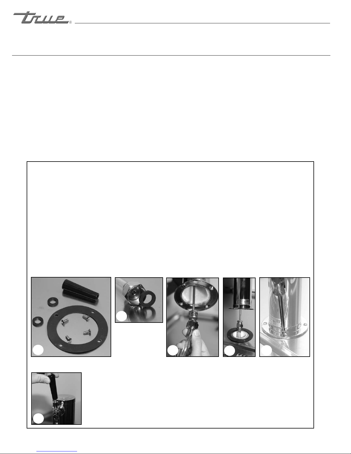
C. Remove door bracket on swinging glass door
models (see image 1-2).
Note: Keys for coolers with door locks are located
in warranty packets.
UNCRATING
INSTALLATION / OPERATION INSTRUCTIONS
1
2
REMOTE UNITS (This section applies to
remotes only!)
• Remote cabinets must be ordered as remote.
We do not recommend converting for a standard
self contained to remote system.
• All remote cabinets must be hard wired.
• No castors available.
• All remote cabinets come standard using 404A
refrigerant.
• All remote units come standard with expansion
valve, liquid line solenoid, heated condensate
pan, and defrost timer when applicable.
• Contact True Technical Service for BTU
requirements.
• No wiring necessary between cabinet and
condensing unit.
• All remote condensing units purchased from
True are 208/230 volts single phase.
If you have any questions regarding this
section, please call True at 1-(800)-325-6152.

............ www.truemfg.com ............
INSTALLATION / OPERATION INSTRUCTIONS
True Food Service Equipment, Inc.
5
55
5
TOOLS REQUIRED:
• Phillips screw driver
• 3/8” socket or 3/8” wrench
Step 2
A. Use a phillips screw diver and remove four
screws from the L-bracket connected the unit to
the wood skid (see image 1).Then use a 3/8”
socket or wrench and remove the L-bracket
from the unit (see image 2).
When lifting unit remember to
leave the cabinet upright for 24 hours before
plugging into power source.
B. Remove skid by unscrewing all base rail anchor
brackets. Place skid to the side.
C. Carefully upright cabinet.
LOCATING
(image 1)
Removing
bracket from
skid.
(image 2)
Removing
bracket from
cabinet.
Step 3
A. Set unit in its final location. Be sure there is
adequate ventilation in your room. Under extreme
heat conditions, (100°F+, 38°C+), you may want to
install an exhaust fan.
Warning
Warranty is void if ventilation is insufficient.
B. Proper leveling of your True cooler is critical to
operating success (for non-mobile models). Effective
condensate removal and door operation will be
effected by leveling.
C. The cooler should be leveled front to back and
side to side with a level.
D. Ensure that the drain hose or hoses are
positioned in the pan.
E. Free plug and cord from inside the lower rear of
the cooler (do not plug in).
F. The unit should be placed close enough to the
electrical supply so that extension cords are never
used.
Warning
Compressor warranties are void if the unit is more
than 7 ft. (2.1m) from plug-in connection or an
extension cord is used to connect unit to a power
supply.
LEVELING

............ www.truemfg.com ............
True Food Service Equipment, Inc.
INSTALLATION / OPERATION INSTRUCTIONS
6
66
6
Wire Gauge for 2% Voltage Drop in Supply Circuits
115 Volt Distance In Feet To Center of Load
Amps 20 30 40 50 60 70 80 90 100 120 140 160
2 141414141414141414141414
3 141414141414141414141412
4 141414141414141414121212
5 141414141414141212121010
6 141414141414121212101010
7 1414141414121212101010 8
8 14141414121212101010 8 8
9 141414121212101010 8 8 8
10 14 14 14 12 12 10 10 10 10 8 8 8
12 14 14 12 12 10 10 10 8 8 8 8 6
14 14 14 12 10 10 10 8 8 8 6 6 6
16 14 12 12 10 10 8 8 8 8 6 6 6
18 14 12 10 10 8 8 8 8 8 8 8 5
20 14 12 10 10 8 8 8 6 6 6 5 5
25 12 10 10 8 8 6 6 6 6 5 4 4
30 12 10 8 8 6 6 6 6 5 4 4 3
35 10 10 8 6 6 6 5 5 4 4 3 2
40 1088665544322
45 1086665443321
50 1086654433211
Wire Gauge for 2% Voltage Drop in Supply Circuits
230 Volts Distance In Feet To Center of Load
Amps 20 30 40 50 60 70 80 90 100 120 140 160
5 141414141414141414141414
6 141414141414141414141412
7 141414141414141414141212
8 141414141414141414121212
9 141414141414141412121210
10 14 14 14 14 14 14 14 12 12 12 10 10
12 14 14 14 14 14 14 12 12 12 10 10 10
14 14 14 14 14 14 12 12 12 10 10 10 8
16 14 14 14 14 12 12 12 10 10 10 8 8
18 14 14 14 12 12 12 10 10 10 8 8 8
20 14 14 14 12 10 10 10 10 10 8 8 8
25 14 14 12 12 10 10 10 10 8 8 6 6
30 14 12 12 10 10 10 8 8 8 6 6 6
35 14 12 10 10 10 8 8 8 8 6 6 5
40 14 12 10 10 8 8 8 6 6 6 5 5
50 12 10 10 8 6 6 6 6 6 5 4 4
60 12 10 8 6 6 6 6 6 5 4 4 3
70 10 10 8 6 6 6 5 5 4 4 2 2
80 1088665544322
90 1086655443311
100 1086654433211
CONDUCTORS AND CIRCUITS

............ www.truemfg.com ............
INSTALLATION / OPERATION INSTRUCTIONS
True Food Service Equipment, Inc.
7
77
7
Step 1 - Position Cabinet
Allow one inch between the wall and rear of the
refrigerated Bar Equipment to assure proper
ventilation. For Glass & Plate Chillers/Frosters 3
inches between the wall and rear of the cabinet
will assure proper ventilation.
Step 2 - Level Cabinet
Cabinet should be level, side to side and front to
back. Place a carpenter’s level in the interior floor
in four places:
A. Position level in the inside floor of the unit near
the doors. (Level should be parallel to cabinet
front). Level cabinet.
B. Position level at the inside rear of cabinet.
(Again level should be placed parallel to cabinet
back).
C. Perform similar procedures to steps A& Bby
placing the level on inside floor (left and right
sides - parallel to the depth of the cooler). Level
cabinet.
Step 3
Draw an outline on the base on the floor.
Step 4
Raise and block the front side of the cabinet.
Step 5
Apply a bead of “NSF Approved Sealant”, (see list
below), to floor on half inch inside the outline
drawn. The bead must be heavy enough to seal the
entire cabinet surface when it is down on the
sealant.
Step 6
Raise and block the rear of the cabinet
Step 7
Apply sealant on floor as outlined in Step 5 on
other three sides.
Step 8
Examine to see that cabinet is sealed to floor
around entire perimeter.
Note:
Asphalt floors are very susceptible to chemical
attack. A layer of tape on the floor prior to
applying the sealant will protect the floor.
NSF Approved Sealants:
1. Minnesota Mining #ECU800 Caulk
2. Minnesota Mining #ECU2185 Caulk
3. Minnesota Mining #ECU1055 Bead
4. Minnesota Mining #ECU1202 Bead
5. Armstrong Cork - Rubber Caulk
6. Products Research Co. #5000 Rubber Caulk
7. G.E. Silicone Sealer
8. Dow Corning Silicone Sealer
SEALING CABINET TO FLOOR

............ www.truemfg.com ............
True Food Service Equipment, Inc.
8
88
8
INSTALLATION / OPERATION INSTRUCTIONS
Step 4
A. Before your new unit is connected to a power
supply, check the incoming voltage with a voltmeter. If
anything less than 100% of the rated voltage for
operation is noted, correct immediately.
B. All units are equipped with a 7 ft. (2.1m) service
cord, and must be powered at proper operating voltage
at all times. Refer to cabinet data plate for this voltage.
True recommends that a sole use circuit be dedicated
for the unit.
WARNING
Compressor warranties are void if compressor burns
out due to low voltage.
WARNING
Power supply cord ground should not be removed!
NOTE
To reference wiring diagram - Remove front louvered
grill, wiring diagram is positioned on the inside cabinet
wall.
ELECTRICAL INSTRUCTIONS
On beer dispensers the drain is located at the
front of the cabinet.To plumb in the drain,
connect 3⁄4" (2cm) P.V.C. pipe to the 3⁄4" (2cm)
barbed fitting supplies with the unit.
CO2 PRESSURE
Mobile tapsters, to retain complete mobility,
the CO2 tank (up to five pounds in size) can
be placed inside the cooler (strap holders
furnished).
CAUTION
Filled CO2 tanks are potentially dangerous
because of the pressure they contain. If you
are unfamiliar with their use or the use of the
CO2 regulator, seek information from your
local distributor, or your local beverage man
before proceeding.
INSTALL DRAFT ARM
Place rubber washer over draft arm mounting
holes in cabinet, put beer line connector down
through hole. Next, secure draft arm with four
screws. (See images 1-6)
BEER DISPENSERS
CONTINUED ON
NEXT PAGE...
Draft arm install contents.
(Draft arm not shown)
Beer line
connector.
Thread beer line connector to draft arm and secure draft
arm to cabinet with rubber gasket under the draft arm.
Thread
beer draft
arm handle
onto the
draft arm.
1
2
345
6

............ www.truemfg.com ............
True Food Service Equipment, Inc.
9
99
9
INSTALL DRAFT ARM continued...
Insert air hose (one inch plastic tube) in
draft arm, being careful not to disturb
insulation. Remove top cover of draft
arm and attach air hose clip to the
insulating sleeve at the top of the draft
arm. Replace top cover. The air hose
clip will assure that the hose remains in
proper place at all times, keeping the
beer faucet cold. (See image 7-9)
INSTALLATION / OPERATION INSTRUCTIONS
BEER DISPENSERS CONTINUED...
789
Step 5
A. The compressor is ready to operate. Plug in the
cooler.
B. Temperature control set at No. 4 position gives
refrigerators an approximate temperature of 35°F
and glass chiller frosters have an approximate
temperature of 0°F. Allow unit to function several
hours, completely cooling cabinet before changing
the control setting.
C. Excessive tampering with the control could lead
to service difficulties. Should it ever become
necessary to replace temperature control, be sure it
is ordered from your True dealer or recommended
service agent.
D. Good air flow in your True unit is critical. Be
careful to load product so that it neither presses
against the back wall, nor comes within four inches
of the evaporator housing. Refrigerated air off the
coil must circulate down the back wall.
LIGHT SWITCH LOCATION:
The switch is located on the front of the
evaporator housing toward the front of the
cabinet. Open the front doors and the switch will
be visible close to the ceiling the cabinet.
NOTE
If the unit is disconnected or shut off, wait five
minutes before starting again.
RECOMMENDATION
Before loading product we recommend you run
your True unit empty for two to three days. This
allows you to be sure electrical wiring and
installation are correct and no shipping damage
has occurred. Remember, our factory warranty
does not cover product loss!
REPLACEMENT PARTS
TRUE maintains a record of the cabinet serial
number for your cooler. If at any time during the
life of your cooler, a part is needed, you may
obtain this part by furnishing the model number
and serial number to the company from whom
you purchased the cooler. Call Toll-Free: (800)-
424-TRUE (Direct to Parts Department). (800)-
325-6152 (U.S.A. & Canada only) or call: (636)-
240-2400.
STARTUP

............ www.truemfg.com ............
True Food Service Equipment, Inc.
10
10 10
10
Shelf
Clip
Shelf
Shelf
Pillaster
(I-beam)
Shelf
Standards
;;;;;;;;;;;;;;;;;;;;;;;;;;
;;;;;;;;;;;;;;;;;;;;;;;;;;;;;;;;;;;;;;;;;;;;;;;;;;;;
;;;;;;;;;;;;;;;;;;;;;;;;;;;;;;;;;;;;;;;;;;;;;;;;;;;;;;;;;;;;;;;;;;;;;;;;;;;;;;;
;;;;;;;;;;;;;;;;;;;;;;;;;;;;;;;;;;;;;;;;;;;;;;;;;;;;;;;;;;;;;;;;;;;;;;;;;;;;;;;;;;;;;;;;;;;;;;;;;;;;;;;;;;
;;;;;;;;;;;;;;;;;;;;;;;;;;;;;;;;;;;;;;;;;;;;;;;;;;;;;;;;;;;;;;;;;;;;;;;;;;;;;;;;;;;;;;;;;;;;;;;;;;;;;;;;;;;;;;;;;;;;;;;;;;;;;;;
;;;;;;;;;;;;;;;;;;;;;;;;;;;;;;;;;;;;;;;;;;;;;;;;;;;;;;;;;;;;;;;;;;;;;;;;;;;;;;;;;;;;;;;;;;;;;;;;;;;;;;;;;;;;;;;;;;;;;;;;;;;;;;;
;;;;;;;;;;;;;;;;;;;;;;;;;;;;;;;;;;;;;;;;;;;;;;;;;;;;;;;;;;;;;;;;;;;;;;;;;;;;;;;;;;;;;;;;;;;;;;;;;;;;;;;;;;;;;;;;;;;;;;;;;;;;;;;
;;;;;;;;;;;;;;;;;;;;;;;;;;;;;;;;;;;;;;;;;;;;;;;;;;;;;;;;;;;;;;;;;;;;;;;;;;;;;;;;;;;;;;;;;;;;;;;;;;;;;;;;;;;;;;;;;;;;;;;;;;;;;;;
;;;;;;;;;;;;;;;;;;;;;;;;;;;;;;;;;;;;;;;;;;;;;;;;;;;;;;;;;;;;;;;;;;;;;;;;;;;;;;;;;;;;;;;;;;;;;;;;;;;;;;;;;;;;;;;;;;;;;;;;;;;;;;;
;;;;;;;;;;;;;;;;;;;;;;;;;;;;;;;;;;;;;;;;;;;;;;;;;;;;;;;;;;;;;;;;;;;;;;;;;;;;;;;;;;;;;;;;;;;;;;;;;;;;;;;;;;;;;;;;;;;;;;;;;;;;;;;
;;;;;;;;;;;;;;;;;;;;;;;;;;;;;;;;;;;;;;;;;;;;;;;;;;;;;;;;;;;;;;;;;;;;;;;;;;;;;;;;;;;;;;;;;;;;;;;;;;;;;;;;;;;;;;;;;;;;;;;;;;;;;;;
;;;;;;;;;;;;;;;;;;;;;;;;;;;;;;;;;;;;;;;;;;;;;;;;;;;;;;;;;;;;;;;;;;;;;;;;;;;;;;;;;;;;;;;;;;;;;;;;;;;;;;;;;;;;;;;;;;;;;;;;;;;;;;;
;;;;;;;;;;;;;;;;;;;;;;;;;;;;;;;;;;;;;;;;;;;;;;;;;;;;;;;;;;;;;;;;;;;;;;;;;;;;;;;;;;;;;;;;;;;;;;;;;;;;;;;;;;;;;;;;;;;;;;;;;;;;;;;
;;;;;;;;;;;;;;;;;;;;;;;;;;;;;;;;;;;;;;;;;;;;;;;;;;;;;;;;;;;;;;;;;;;;;;;;;;;;;;;;;;;;;;;;;;;;;;;;;;;;;;;;;;;;;;;;;;;;;;;;;;;;;;;
;;;;;;;;;;;;;;;;;;;;;;;;;;;;;;;;;;;;;;;;;;;;;;;;;;;;;;;;;;;;;;;;;;;;;;;;;;;;;;;;;;;;;;;;;;;;;;;;;;;;;;;;;;;;;;;;;;;;;;;;
;;;;;;;;;;;;;;;;;;;;;;;;;;;;;;;;;;;;;;;;;;;;;;;;;;;;;;;;;;;;;;;;;;;;;;;;;;;;;;;;;;;;;;;;;;;;;;
;;;;;;;;;;;;;;;;;;;;;;;;;;;;;;;;;;;;;;;;;;;;;;;;;;;;;;;;;;;;;;;;;;;
;;;;;;;;;;;;;;;;;;;;;;;;;;;;;;;;;;;;;;;;;
;;;;;;;;;;;;;;
O
F
F
9
8
7
6
5
4
3
2
1
SHELVING and BIN DIVIDER INSTALLATION /
OPERATION
INSTALLATION / OPERATION INSTRUCTIONS
SHELF INSTALLATION:
A. Hook shelf clips onto shelf standards.
B. Position all four shelf clips equal in distance
from the floor for flat shelves.
C. Shelves are oriented so that cross support bars
are facing down.
D. Place shelves on shelf clips making sure all
corners are seated properly.
HORIZONTAL BOTTLE COOLER BIN DIVIDER
INSTALLATION:
Horizontal bottle coolers are shipped with bin
dividers in place. If it is necessary to adjust spacing
the following procedure is recommended.
Step 1
A. Dividers are spring loaded - push divider
towards rear of the cooler to release from front
grommeted holes.
B. Lineup divider front pegs with desired holes and
punch through interior tape lining of both top and
bottom holes - bottom peg first (front holes are
taped over to improve insulation values).
Remove divider from the front holes and line up
regular and spring loaded rear pegs with holes in
line with those desired in front. Insert as far as
possible and maneuver front pegs in place.
SHELF INSTALLATION
BIN DIVIDER INSTALLATION
NOTE:
Divider
positioned in
front of
mechanical box
requires specific
notch cut out.
Draft beer should be treated as a food product. In
most instances draft beer is not pasteurized. It is
very important that you store and handle it properly.
Follow these steps to ensure the highest quality and
consumer satisfaction.
• Draft beer should be immediately stored in a
refrigerated cabinet.
• Draft beer products have a recommended shelf
life. If you have questions regarding the shelf life of
any of your draught products, please consult with
your supplying depot or respective Brewer
representative.
• Kegs should be stored separately from food
products. If your cooler is used to refrigerate
draught and food products, it is very important that
the food not be stored near or on the kegs.
• Keg storage and dispensing areas should be kept
clean to prevent any possibility of contaminating
your draught products.
STORAGE AND HANDLING

............ www.truemfg.com ............
True Food Service Equipment, Inc.
11
11 11
11
INSTALLATION / OPERATION INSTRUCTIONS
Dispensing pressures differ according to:
• The type of draft dispensing system
• The length of draft dispensing line
• The actual product - some require
more, some require less
• The temperature of the product
• The pressurizing agent: air pressure,
CO2 or special blended gases.
PRESSURE
• Correct temperature is a key factor to
consider in storing and dispensing draft
beer. Too cool or too warm may cause
flavor loss, off taste and dispensing
problems.
Helpful Hints on Controlling Temperature
• Keep a thermometer handy
• Monitor temperature of draft in your
cooler and at the tap
• Keep cooler door closed as much as
possible to avoid temperature
fluctuation
• Regular maintenance of refrigeration
equipment is recommended
TEMPERATURE
Helpful Hints On Maintaining The
Correct Pressure:
• Know which pressurizing agent to
use on which product and why.
• Monitor your regulators to ensure
applied pressure remains constant
• Keep equipment in good repair
Do not agitate the kegs unnecessarily. If
excessive agitation occurs allow kegs to
settle for 1 to 2 hours before tapping.
Prior to tapping the keg, ensure that all
beer faucet in the serving location are in
the off position. Completely remove the
dust cover (identification cap) from the
keg.
TAPPING

............ www.truemfg.com ............
True Food Service Equipment, Inc.
12
12 12
12
INSTALLATION / OPERATION INSTRUCTIONS
Flat Beer - Description: Foamy head
disappears quickly. Beer lacks
usual zestful brewery fresh flavor.
CO2turned off when not in use.
Contaminated air source (associated
with compressed air).
Greasy glasses.
Not enough pressure.
Pressure shut off during night.
Loose tap or vent connection.
Sluggish pressure regulator.
Obstruction in lines.
False Head - Description: Large soap-
like bubbles, head dissolves very
quickly.
Dry glasses.
Improper pour.
Pressure required does not correspond
to beer temperature.
Coils or direct draw beer lines warmer
than beer in keg.
Small lines into large faucet shanks.
Beer drawn improperly.
Wild Beer - Description: Beer, when
drawn, is all foam and not enough
liquid beer.
Beer drawn improperly.
Faucet in bad or worn condition.
Kinks, dents, twists or other
obstructions in line.
Traps in beer lines.
Beer too warm in kegs or lines.
Too much pressure.
Creeping gauge causing too much
pressure.
Cloudy Beer - Description: Beer in the
glass appears hazy. Not clear.
Dirty glass or faucet.
Beer over chilled.
Beer temperature variance in keg (Beer
may have warmed up at sometime).
Hot spots in beer lines.
Cutting beer through faucet.
Beer line in poor condition.
Dirty lines.
Beer that has been frozen.
Bad Taste
Dirty faucet.
Old or dirty beer lines.
Failure to flush beer lines with water
after each empty keg.
Unsanitary conditions at bar.
Foul air or dirt in lines.
Oily air; greasy kitchen air.
Temperature of package too warm.
Dry glasses
DRAFT BEER PROBLEMS
To minimize draft beer problems, always follow the recommended
instructions for temperature and CO2pressures from your beer supplier.

MAINTENANCE, CARE & CLEANING
TERMS:
Cut-out - Temperature sensed by
the controller that shuts the
compressor off.
Cut-in - Temperature sensed by
the controller that turns the
compressor on.
REQUIRED TOOLS
• Phillips Head Screwdriver
• 5/64" or 2 mm Allen Wrench
• T-7 Torx Wrench
___________ STEP 1 ___________
Unplug the cooler.
___________ STEP 2 ___________
Remove the screws that secure
the temperature control to the
inset box.
___________ STEP 3 ___________
Pull out gently from cabinet.
___________ STEP 4 ___________
For high elevation installations, it
may be necessary to "warm-up"
the set points. To make the
adjustment, insert the
appropriate tool in each
adjustment screw and turn 1/4
of a revolution clockwise (to the
right). This procedure will adjust
both the cut-in and cut-out about
2°F warmer.
___________ STEP 5 ___________
Make sure to reconnect the pink
wire to the proper spade
terminal when reinstalling.
NOTE:
Mechanical temperature
controllers are affected when
functioning at high altitude.
The cut-in and cut-out
temperatures will be colder
than when the controller
functions closer to sea level
Danfoss Temperature Control (High Altitude Adjustment Only!)
Cut-out Adjustment Screw Allen (5/64"
or 2 mm) (clockwise for warmer)
Cut-in Adjustment Screw Torx (T-7)
(clockwise for warmer)
Compressor Connection
(double terminal)
TEMPERATURE CONTROL ADJUSTMENT FOR
HIGH ALTITUDE ONLY!
............ www.truemfg.com ............
True Food Service Equipment, Inc.
13
13 13
13

............ www.truemfg.com ............
True Food Service Equipment, Inc.
14
14 14
14
MAINTENANCE, CARE & CLEANING
Follow these instructions at ALL times when you
replace a CO2gas cylinder:
1. Close cylinder at "A".
2. Remove tap "D" from barrel. Pull pressure
release ring on body of tap to release pressure
remaining in line. (do not close "C")
3. Remove or loosen regulator key "B" by turning
counter clockwise.
4. Remove regulator from used cylinder at "E".
5. Remove dust cap from new gas cylinder at "E"
and clear dust from outlet by opening and
closing valve "A" quickly using appropriate
wrench.
6. Attach regulator to new cylinder at "E". (use
new fiber/plastic washer, if required).
7. Open valve "A" all the way.
8. Close valve "C".
9. Adjust regulator key "B" by turning clockwise to
set pressure. (check setting by opening "C" and
pulling and releasing the ring "F" on the
pressure release valve on the body of the tap)
10.Tap barrel at "D" with valve "C" open.
NOTE
Don't lay CO2cylinders flat.
Don't drop CO2cylinders.
It requires 1/2 pound CO2 to dispense 1/2 barrel
of beer at 38°F with 15 pounds pressure on
barrel.
PRESSURE ADJUSTMENT ON CO2
REGULATOR
Increasing Pressure
1. Close regulator shut-off "C".
2. Turn regulator key "B" clockwise and make
setting.
3. Tap gauge for accurate reading.
4. Open regulator shut-off "C" and draw beer.
Decreasing Pressure
1. Close regulator shut-off "C".
2. Untap barrel at "D" and to bleed line, activate
tap handle. Leave in open position.
3. Slowly open regulator shut-off "C" and
simultaneously turn regulator key counter-
clockwise to zero reading.
4. Close regulator shut-off "C" and set pressure by
turning regulator key clockwise. Check setting
by opening and closing valve "C".
5. Close tap head "D". (put in "OFF" position)
6. Tap barrel at "D" and open regulator shut-off
"C".
CHANGING CO
2
GAS CYLINDER
A
B
C
D
E
F

............ www.truemfg.com ............
True Food Service Equipment, Inc.
15
15 15
15
MAINTENANCE, CARE & CLEANING
Draught dispensers, regardless of design, must be
cleaned at least every two weeks. Flushing your
draught dispenser with water only is not enough.
Note: Use cleaners approved by your beer
supplier and follow their instructions. If you are
using the cleaning kit purchased from True follow
these instructions:
Exacting cleanliness should be constantly
maintained in your dispenser so that your draught
beer will be at its best when served.Although the
beer in the barrel is in excellent condition, it can
become less satisfying as it is drawn through the
beer line and faucet if they are not kept clean.
Prepare Solution:
Add 1/2 ounce (19 grams) of line cleaning
powder to each quart of water, cold or warm.
Cleaning:
1. Disconnect tap from barrel. Remove beer faucet
with spanner wrench unscrew handle and
remove valve assembly (fig. 1).
2. Put tap and faucet parts in a bucket with
cleaning solution to soak.
3. Use small brush to clean beer faucet parts
(fig. 2).
4. Rinse parts Thoroughly.
5. Fill pump bottle with DBK solution.
6. Attach hose from pump bottle to beer column
tap outlet (be sure rubber gasket is in place to
prevent leakage) - allow tap to drain in bucket
(fig. 3).
7. Pump solution (2-3 times from bottle through
the line until it starts to flow out the beer line.
Wait 10 minutes while cleaning solution works on
the lines.
8. Pump excess solution through lines.
9. Rinse bucket, pump bottle and hose thoroughly
with clean cool water.
10.Fill pump bottle with clean cool water and
pump through lines until water runs clear.
11.When crystal clear water comes through, you're
ready to assemble and reattach faucet and re-tap
the barrel.
12.Draw the water from the beer line; now you're
ready to serve brewery fresh, golden beer.
NOTE
Keeping your dispenser and all its parts clean and
odor free will help you to serve beautiful foam topped
glasses of delicious satisfying draught beer.
CLEANING BAR SYSTEM
fig. 1 fig. 2 fig. 3
Beer Tap Cleaning Kit
Required Tools
line cleaning
powder
Spanner
wrench
Brush
Pump
bottle and
Bucket and
fresh water

............ www.truemfg.com ............
True Food Service Equipment, Inc.
16
16 16
16
MAINTENANCE, CARE & CLEANING
CLEANING THE CONDENSER COIL
When using electrical appliances, basic safety precautions should be followed, including the following:
T
M
C
TRUE
REQUIRED TOOLS
• Phillips Screwdriver
• Stiff Bristle Brush
• Adjustable Wrench
STEP 1
Disconnect power to unit.
STEP 2
Take off lower grill assembly by removing all
screws.
STEP 3
Remove bolts anchoring compressor assembly to
frame rails and carefully slide out. (tube
connections are flexible)
STEP 4
Clean off accumulated dirt from condensing coil
with a stiff bristle brush.
STEP 5
Lift cardboard cover above fan at plastic plugs and
carefully clean condenser coil and fan blades.
STEP 6
After brushing condenser coil vacuum dirt from
coil, and interior floor.
STEP 7
Replace cardboard cover. Carefully slide
compressor assembly back into position and
replace bolts.
STEP 8
Reinstall louver assembly onto unit with
appropriate fasteners and clips. Tighten all
screws.
STEP 9
Connect unit to power and check to see if
condenser is running.

............ www.truemfg.com ............
True Food Service Equipment, Inc.
17
17 17
17
Condensers accumulate dirt and require cleaning every 30 days. Dirty condensers result in compressor
failure, product loss, and lost sales... which are not covered by warranty.
If you keep the Condenser clean you will minimize your service expense and lower your electrical costs.
The Condenser requires scheduled cleaning every thirty days or as needed.
Air is pulled through the Condenser continuously, along with dust, lint, grease, etc.
A dirty Condenser can result in NON-WARRANTEED part & Compressor Failures, Product Loss, and Lost
Sales.
Proper cleaning involves removing dust from the Condenser. By using a soft brush, or vacuuming the
Condenser with a shop vac, or using CO2, nitrogen, or pressurized air.
If you cannot remove the dirt adequately, please call your refrigeration service company.
On most of the reach-in units the condenser is accessible in the rear of the unit. You must remove the
cabinet grill to expose the Condenser.
The Condenser looks like a group of vertical fins. You need to be able to see through the condenser for
the unit to function at maximum capacity. Do not place filter material in front of condensing coil. This
material blocks air-flow to the coil similar to having a dirty coil.
THE CLEANING OF THE CONDENSER IS NOT
COVERED BY THE WARRANTY!
HOW TO CLEAN THE CONDENSER:
1. Disconnect the electrical power to the unit.
2. Remove the louvered grill.
3. Vacuum or brush the dirt, lint, or debris from the finned condenser coil.
4. If you have a significant dirt build up you can blow out the condenser with compressed air.
(CAUTION MUST BE USED to avoid eye injury. Eye protection is recommended.)
5. When finished be sure to replace the louvered grill. The grill protects the condenser.
6. Reconnect the electrical power to the unit.
If you have any questions, please call True Manufacturing at 636-240-2400 or 800-325-6152 and ask for the
Service Department. Service Department Availability Monday-Friday 7:30 a.m. to 5:30p.m.
and Saturday 7:45 a.m. to 11:45 a.m. CST.
MAINTENANCE, CARE & CLEANING
Condensing Unit
AirflowAirflowAirflow
Condenser
IMPORTANT WARRANTY INFORMATION

............ www.truemfg.com ............
True Food Service Equipment, Inc.
18
18 18
18
MAINTENANCE, CARE & CLEANING
CAUTION: Do not use any steel wool, abrasive or chlorine based products to clean stainless
steel surfaces.
Stainless Steel Opponents
There are three basic things which can break down your stainless steel’s passivity layer and allow
corrosion to rear its ugly head.
1) Scratches from wire brushes, scrapers, and steel pads are just a few examples of items that can be
abrasive to stainless steel’s surface.
2) Deposits left on your stainless steel can leave spots. You may have hard or soft water depending on
what part of the country you live in. Hard water can leave spots. Hard water that is heated can
leave deposits if left to sit too long. These deposits can cause the passive layer to break down and
rust your stainless steel. All deposits left from food prep or service should be removed as soon as
possible.
3) Chlorides are present in table salt, food, and water. Household and industrial cleaners are the worst
type of chlorides to use.
8 steps that can help prevent rust on stainless steel:
1. Using the correct cleaning tools
Use non-abrasive tools when cleaning your stainless steel products. The stainless steel’s passive layer
will not be harmed by soft cloths and plastic scouring pads. Step 2 tells you how to find the
polishing marks.
2. Cleaning along the polish lines
Polishing lines or “grain” are visible on some stainless steels. Always scrub parallel to visible lines on
some stainless steels. Use a plastic scouring pad or soft cloth when you cannot see the grain.
3. Use alkaline, alkaline chlorinated or non-chloride containing cleaners
While many traditional cleaners are loaded with chlorides, the industry is providing an ever
increasing choice of non-chloride cleaners. If you are not sure of your cleaner’s chloride content
contact your cleaner supplier. If they tell you that your present cleaner contains chlorides, ask if
they have an alternative. Avoid cleaners containing quaternary salts as they can attack stainless steel,
causing pitting and rusting.
4. Water Treatment
To reduce deposits, soften the hard water when possible. Installation of certain filters can remove
corrosive and distasteful elements. Salts in a properly maintained water softener can be to your
advantage. Contact a treatment specialist if you are not sure of the proper water treatment.
5. Maintaining the cleanliness of your food equipment
Use cleaners at recommended strength (alkaline, alkaline chlorinated or non-chloride). Avoid
build-up of hard stains by cleaning frequently. When boiling water with your stainless steel
equipment, the single most likely cause of damage is chlorides in the water. Heating any cleaners
containing chlorides will have the same damaging effects.
6. Rinse
When using chlorinated cleaners you must rinse and wipe dry immediately. It is better to wipe
standing cleaning agents and water as soon as possible. Allow the stainless steel equipment to air
dry. Oxygen helps maintain the passivity film on stainless steel.
7. Hydrochloric acid (muriatic acid) should never be used on stainless steel
8. Regularly restore/passivate stainless steel
Stainless Steel Equipment Care and Cleaning
Other manuals for TBB-2
1
This manual suits for next models
4
Table of contents
Other True Refrigerator manuals
Popular Refrigerator manuals by other brands

KitchenAid
KitchenAid KRSC503ESS Installation instructions and owner's manual

KitchenAid
KitchenAid KSSS36QMB00 parts list

Bosch
Bosch B36IT71SNS - 20 cu. Ft. Refrigerator Specifications

Foster
Foster HR80MF Service manual

Electrolux
Electrolux ER6247T Installation and instruction manual

Hitachi
Hitachi R-S57YMJ How to use